DOI:
10.1039/C5RA21936A
(Paper)
RSC Adv., 2015,
5, 105524-105530
Controlled electro-coalescence/non-coalescence on lubricating fluid infused slippery surfaces†
Received
20th October 2015
, Accepted 27th November 2015
First published on 30th November 2015
Abstract
Aqueous drops on silicone oil infused lubricating surfaces are cloaked with a thin layer of oil to minimize their surface energy. These oil cloaked aqueous drops exhibit pseudo-stable coalescence or spontaneous coalescence depending upon the lubricating oil thickness which controls the interaction point of the drops. For thick oil films, drops interact with each other through the surrounding oil menisci resulting in pseudo-stable non-coalescence due to a thin oil layer between the drops. This stabilizing oil layer drains itself out due to the Laplace pressure of the aqueous drops. An external electric field applied between the drops forces the oil to drain faster, due to additional electrostatic pressure, resulting in faster coalescence. This happens in two steps: bulk drainage of the oil and final rupture due to the electric field induced hydrodynamic instability of the thin oil layer. For thin lubricating films, the contact point of aqueous drops is in the vicinity of the water–air interface resulting in spontaneous coalescence. By applying an external electric field between the drops and substrate (to decrease the apparent contact angle by electrowetting), the interaction point is brought close to the oil meniscus resulting in pseudo-stable aqueous drops against coalescence.
Introduction
Inspired by Nepenthes pitcher plants, Aizenberg et al. demonstrated lubricant infused porous Teflon membranes as slippery surfaces which repel and slip different immiscible liquids upon tilting by a small angle.1 Such lubricant infused slippery surfaces have found a variety of applications including self cleaning,2,3 self healing against mechanical damage,1 fog harvesting,4 enhanced condensation,5 drag reduction,6 reduction of ice nucleation7,8 and ice adhesion,9–11 omniphobic textiles,12 biofouling,13,14 and anti-corrosion,15 to name a few. Since then, various research groups have attempted different ways to fabricate slippery surfaces and explored related phenomena.2,4,5,7–10,13,16–24 Necessary conditions for stable slippery surfaces can be summarized as: (a) complete wetting of the lubricant on substrates, (b) immiscibility of the lubricant with the slipping fluid, and (c) non-wetting of the slipping fluid with the substrate.1 One of the most common slippery surfaces is the oil infused substrate for slipping water drops.2,6,16,23,25 For a water–oil system, the stability criteria can be stated in terms of its spreading parameters such that the oil-substrate spreading coefficient Sos (=γsa − γos − γoa) ≥ 0 and the water-substrate spreading coefficient Sws (=γsa − γws − γwa) < 0 where γ is the interfacial tension and o, s, w and a represent oil, substrate, water and air phases respectively. In other words, the substrate has to be oleophilic as well as hydrophobic. The contact angle of water drops on solid surfaces is governed by Young’s law (liquid–solid interface), whereas on oil infused slippery surfaces it is governed by Neumann’s law (liquid–liquid interface).26–28 Therefore water drops on thin oil films show a kink at the three phase contact point due to pulling of the oil. To minimize the interfacial energy, water drops on oil infused surfaces get cloaked by a thin layer of oil. This happens if the spreading parameter of oil on water is greater than or equal to zero.17 Recently the cloaking as well as kinking of a water drop on lubricant infused surfaces was experimentally observed using a high resolution optical microscope and laser scanning confocal microscope.21,29 However, most of the studies on slippery surfaces are focused on the static and dynamic behavior of drops and lubricating fluid, and very few studies have been done on the interactions of multiple drops on slippery surfaces. Collier et al. demonstrated the interaction of two water drops on a lubricant infused slippery surface which leads to coalescence or non-coalescence depending upon their interaction point.18 Similar non-coalescence is observed for water drops submerged in crude oil due to surface active elements like resins and asphaltene which accumulate on the interface of the drops preventing coalescence.30 The interaction of water drops submerged in oil in the absence of any stabilizing agent exhibits spontaneous coalescence.31–34 Coalescence of water drops in oil induced by an external electric field is well reported in various contexts.35–40 Kavehpour et al. demonstrated the effect of a dc electric field on electro-coalescence of conducting drops separated by silicone oil.40 Hasted et al. reported the effect of viscosity of the oil medium on electro-coalescence of water drops.39 Recently scaling down the electro-coalescence phenomenon has been demonstrated to microfluidic lengths for mixing and chemical analysis applications.41–45 Various research groups studied the effect of different parameters e.g. ac/dc electric field,43,46 drop size,43,44,46 viscosity of oil,45 separation between drops42etc. on electro-coalescence in microfluidic devices.
Electric field induced contact angle variation (electrowetting) of water drops has been demonstrated as an important tool for various phenomena.47–54 Recently a few research groups showed electrowetting of water drops on lubricant infused slippery surfaces.19,20,25 Conventionally, a thin solid dielectric is used in electrowetting but on lubricant (which can also be dielectric) coated slippery surfaces, the thin layer of oil acts an additional dielectric layer.19,25 Electrowetting hysteresis is also reported to be decreased significantly on these slippery surfaces.20 However, no study has been done to date on controlling the coalescence or non-coalescence of water drops on the lubricating fluid infused slippery surfaces.
In this article, we report non-coalescence and spontaneous coalescence of two water drops on silicone oil coated hydrophobic silicon substrates. The non-coalescing drops are forced to coalesce upon applying a small ac voltage between them. The applied voltage drains out the stabilizing oil layer between the drops forcing them to coalesce. A theoretical model is also developed to estimate the drainage rate of oil, thus predicting the life time of the non-coalescence. In the case of spontaneous coalescence, electrowetting is used to decrease the apparent contact of aqueous drops. With decreased contact angles, the interacting water drops show stable non-coalescence.
Experimental section
Electro-coalescence and electrowetting experiments were done on p-type 〈100〉 silicon (Si) wafers (UniversityWafers, USA) with a thin (1 μm ± 0.15) insulating layer of SiO2 on top. Smooth silicon substrates were preferred over rough or porous substrates as they provide exact information about the dielectric thickness, lubricant thickness and effective dielectric constant. These substrates were cleaned in an ultrasonic bath of ethanol, acetone, and toluene for 5 min each followed by O2 plasma cleaning. Since the top surface of substrates has to be hydrophobic as well as oleophilic to achieve stable slippery surfaces, a self-assembled monolayer of octadecyltrichlorosilane (OTS) molecules was grafted on the SiO2 surface.55 Silicone oil with a dynamic viscosity (η) of 350 cSt (Sigma Aldrich) was used as the lubricating fluid and cast by spin coating at 400 and 1000 rpm on the OTS coated substrates. Thickness of the lubricating oil films was estimated using a weight difference method which was found to be around 100 μm and 20 μm for 400 and 1000 rpm respectively. Evaporation of the lubricating fluid is an important parameter that affects the electro-coalescence/non-coalescence experiments as it changes the thickness of the lubricating film. Therefore we used freshly prepared samples for all the experiments to ignore any effect due to lubricating fluid evaporation. For all electro-coalescence and electrowetting experiments, a 10 μL volume of deionised water drops was used with 3 wt% salt (NaCl) to make it conductive. Platinum wires (diameter ∼ 70 μm) were used as electrodes to apply an electric field and an ac voltage of different frequencies was supplied from a function generator. The top view and side view of the experiments were captured using a stereo microscope and a contact angle Goniometer (OCA35, DataPhysics, Germany) which provided the information about coalescence and contact angles.
Results and discussion
For our experimental system, the spreading parameter of silicone oil on water comes out at around 6 mJ m−2 which confirms that the aqueous drops are cloaked with a thin layer of oil.
Fig. 1 shows schematic illustrations of the interaction of two aqueous drops on oil coated solid surfaces. For a thick lubricating film, the drops contact each other through an oil meniscus and a thin layer of the oil is pulled between the drops resulting in a pseudo-stable non-coalescence state (Fig. 1(a)). This non-coalescence is not permanent as the thin oil layer is slowly drained due to the Laplace pressure of the drops. Therefore it is a kinetic process rather than a stable thermodynamic situation. All the non-coalescence states in this study are pseudo-stable non-coalescence but will be termed non-coalescence for simplicity. Meanwhile for thin lubricating films, the point of contact is well above the oil surface (at the water–air interface) resulting in spontaneous coalescence (Fig. 1(b)). Eqn (1) summarizes the conditions for non-coalescence in terms of the apparent contact angle and various length scales:
| | | θ < 90° or θ > 90°, R < L + L0 | (1) |
where
R,
L and
L0 represent the drop radius, drop base radius and oil meniscus length respectively.
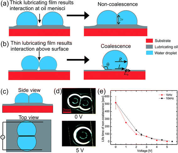 |
| | Fig. 1 Schematic illustration of the interaction of two aqueous drops on silicone oil coated solid surfaces indicating non-coalescence (a) or coalescence (b) depending on the interaction point. Electro-coalescence of non-coalescing aqueous drops on thick (100 μm) silicone oil coated solid substrates. (c) Schematic illustration of the experimental setup, (d) optical micrographs of drops at 0 V and 5 V showing electro-coalescence, and (e) a plot of the non-coalescence life time as a function of the applied ac voltage for two different frequencies. | |
(a) Electro-coalescence using an external electric field
Non-coalescing drops can be forced to coalesce or in other words, the life time of non-coalescence can be reduced through an external electric field. To achieve this, substrates with a 100 μm thick silicone oil coating were used because they will provide the necessary conditions for non-coalescence as given by eqn (1). When two aqueous drops deposited on such an oil coated surface are brought into contact, a thin layer of oil is pulled between the two drops resulting in non-coalescence. If we wait for a sufficiently long time (about 10 min), these non-coalescing drops also coalesce due to the drainage of oil between the drops showing the finite life time of the non-coalescence. This life time of the non-coalescence can be lowered significantly (to almost instantaneous) by applying an external electric field between the two aqueous drops. Fig. 1 shows a schematic illustration of the experimental setup, optical micrographs of the electro-coalescing drops and a plot of the non-coalescence life time as a function of the applied ac voltage (Vrms). It is clear from Fig. 1(e) that as the applied voltage is increased, the life time of non-coalescence is decreased and at about 5 V, the electro coalescence happens almost instantaneously (see ESI movie S1†). Ambient temperature also plays an important role in electro-coalescence as it changes the viscosity of the lubricating fluid. It was observed that the life time of non-coalescence decreases as a function of increasing temperature (see ESI Fig. S1†). Therefore, in addition to the external electric field, temperature can be used to manipulate the non-coalescence phenomenon on lubricating fluid coated slippery surfaces.
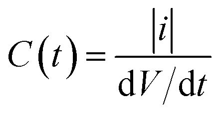
To understand the effect of the electric field on the life time of non-coalescence, current through the circuit was measured as a function of time for different applied voltages. Since the silicone oil used as the lubricating liquid film in the experiment is a good dielectric (∊r = 2.75), the pulled oil film in between the conducting aqueous drops can be modelled as a parallel plate capacitor. The electro-coalescence experiments are performed on Si substrates and, with a thick 1 μm SiO2 coating, flow of the short-circuit current through the substrate after complete drainage of the oil film is prevented. Capacitance of the oil film between the two drops can be written as  , where |i| is the amplitude of the measured current through the drops and
  is the slew rate of the applied ac voltage, which will be 2πVf where V and f are the amplitude and frequency of the applied ac voltage respectively. Thus, one can easily estimate the thickness of the oil film between the two aqueous drops at any time t as:
| |  | (2) |
where
A is the surface area of the oil film between the two drops. During the experiments, current in the circuit was measured as a function of time for different applied ac voltages, which was subsequently used to derive the change in the oil film thickness.
Fig. 2(a) shows the measured ac current between two non-coalescing aqueous drops as a function of time for different voltages at a frequency of 10 kHz. As the aqueous drops are brought into contact, the current increases sharply to reach an optimum value corresponding to that particular value of oil film thickness. Later, with increasing time, the oil is drained, decreasing the oil film thickness and the current keeps increasing. When the two drops coalesce, after the oil film is completely drained, the current diverges reaching a maximum value of 600 μA (short circuit current). Oil film thickness was calculated using the measured current and
eqn (2) and is plotted in
Fig. 2(b) confirming the decrease in thickness as a function of time.
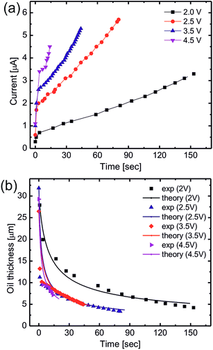 |
| | Fig. 2 (a) Measured current in the circuit as a function of time for different applied ac voltages, and (b) experimental and calculated oil film thickness variation as a function of time for different applied ac voltages. | |
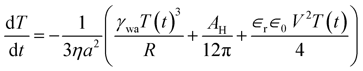
In our experiments, the size of aqueous drops is kept well below the capillary length  (γ and ρ being the surface tension and density of water and g is the acceleration due to gravity) so the effect of gravity could be safely neglected. In the absence of an external electric field, coalescence of aqueous drops occurs solely due to the Laplace pressure driven decrease in oil film thickness and that is why it takes a much longer time (∼600 s). With an applied voltage, the coalescence becomes much faster due to the added contribution of electrostatic pressure. Therefore one can write the total pressure difference (ΔP) between the two drops, which is responsible for oil film drainage, as:
| |  | (3) |
where
R is the radius of the coalescing drops and
AH is the Hamaker constant (∼10
−18 J).
56 Solving the Navier–Stokes equation with proper boundary conditions and
eqn (3) yields an oil film drainage rate of (see ESI
†):
| |  | (4) |
where 2
a is the diameter of the oil film formed between the two aqueous drops as shown in
Fig. 1(a).
Eqn (4), which represents the oil film drainage rate, was fitted numerically to the experimental data and is plotted as solid lines in
Fig. 2(b). The oil film radius ‘
a’ was used as a fitting parameter and was kept constant at 500 μm for different voltages which matches with the experiments. Here one should note that during electro-coalescence at a fixed voltage, the oil film radius does not vary and only its thickness decreases resulting in coalescence at a longer time scale. At early times, the flow rate is higher due to a thick oil film and the rate decreases as the oil film thickness is decreased.
The process of electro-coalescence happens in two steps: first, drainage of the oil film due to flow and second, rupture of the oil film below a critical thickness due to an electric field induced hydrodynamic instability. As shown in Fig. 2(b), oil film thickness decreases to a minimum (saturation) value below which there is no further oil flow. This defines the critical (minimum) film thickness and the onset of electric field induced hydrodynamic instability which is plotted in Fig. 3. The critical film thickness depends upon the applied voltage and is found to be in the range of a few microns which leads to a critical electric field around 615 kV m−1 as shown in the Fig. 3 inset. However, the critical electric field for the dielectric breakdown of silicone oil in air is Ebreakdownc ≈ 15 MV m−1, which clearly suggests that the final rupture of the oil film is not due to the dielectric breakdown of silicone oil. Also the process of the final rupture of the oil film is much faster (a few milliseconds) compared to the drainage time (tens of seconds). Priest et al. have also demonstrated a similar electro-coalescence phenomenon of aqueous drops in oil (emulsions) in microfluidic devices showing very similar behavior.42 Herminghaus et al. have also shown theoretically that a thin dielectric liquid film between two conducting media undergoes dynamic instability if a potential difference is applied across it.57 The time required for rupture of the oil–water interface is in the order of milliseconds which is consistent with our coalescence experiment.
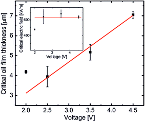 |
| | Fig. 3 Critical thickness of the oil film after drainage as a function of applied voltages. Inset: critical electric field for rupture of the oil film due to dynamic instability. | |
(b) Non-coalescence using electrowetting on dielectric (EWOD)
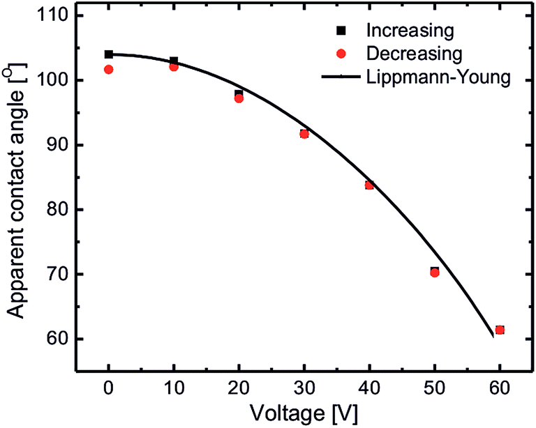
EWOD induced coalescence experiments were done on substrates coated with silicone oil with a thickness of approximately 20 μm. In this situation, interaction of aqueous drops deposited on these substrates is initiated from almost the middle of the drops (at the water–air interface) resulting in spontaneous coalescence (cf.Fig. 1(b)). Such coalescence of aqueous drops can be prevented by lowering the interaction point of the drops (close to the oil meniscus). This can be achieved using electrowetting on dielectrics by lowering the apparent contact angle of the aqueous drops. Fig. 4 shows the EWOD plot of a conducting aqueous drop on silicone oil coated substrates for increasing and decreasing voltage cycles at a 10 kHz ac voltage. Due to the lubricating (slippery) nature of silicone oil, it provides very smooth movement of the three phase contact point of the aqueous drop during electrowetting thus resulting in extremely low contact angle hysteresis (∼2°). Electrowetting behavior is qualitatively explained by the Lippmann–Young equation as:| | 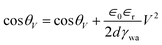 | (5) |
where d is the thickness of dielectrics which in the present case will be the sum of silicone oil thickness plus solid SiO2 thickness. The black solid line in Fig. 4 represents eqn (5) which is fitted to the increasing voltage cycle.
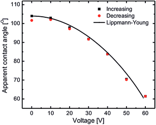 |
| | Fig. 4 Electrowetting on dielectrics plot of an aqueous drop on silicone oil coated substrates for increasing and decreasing voltage cycles showing extremely low hysteresis. The black solid line represents the Lippmann–Young equation which is fitted numerically to the experiment data (increasing voltage cycle). | |
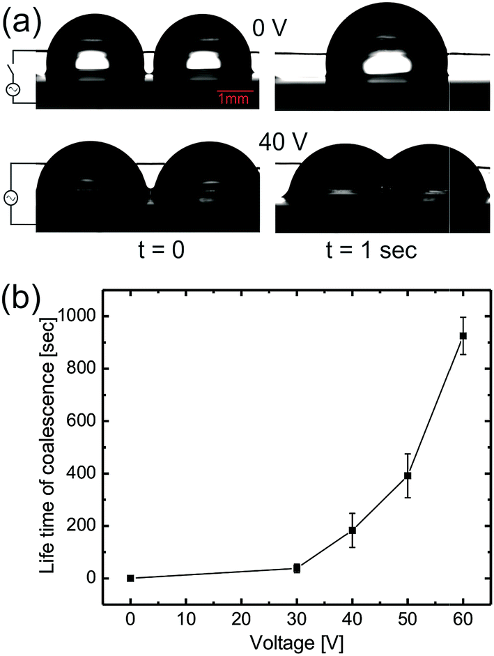
As voltage is increased during electrowetting, due to lowering of the apparent contact of aqueous drops, the interaction point of the interacting aqueous drops is lowered close to the oil meniscus. Therefore as the drops touch each other, a thin layer of oil is pulled up between the two drops, thus bringing the drops into a non-coalescing regime with an increased non-coalescence life time (see ESI movie S2†). For electrowetting induced non-coalescence experiments, a horizontal copper wire was brought into contact with the aqueous drops which acts as a top electrode and a bottom electrode was connected to the base of p-type Si substrates as shown in Fig. 5(a). Fig. 5(a) also shows spontaneous coalescence of two aqueous drops upon contact without an applied voltage whereas the bottom row shows stable non-coalescence of the drops after 40 V. Fig. 5(b) shows the plot of increasing coalescence life time of aqueous drops as a function of applied voltage.
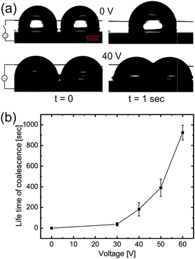 |
| | Fig. 5 Electrowetting on dielectrics induced non-coalescence of aqueous drops. (a) Optical snap shots of coalescing and non-coalescing aqueous drops without and with applied voltage, (b) coalescence life time of aqueous drops as a function of applied voltage during electrowetting. | |
During EWOD, the apparent contact of the aqueous drops remains above 90° up to 30 V therefore the drops still remain in the spontaneous coalescence regime. Above 40 V, the aqueous drop’s contact angle is brought below 90° bringing the interaction point closer to the oil meniscus thus increasing the coalescence life time. Upon further increasing the voltage up to 60 V, the apparent contact angle decreases to 60°, increasing the coalescence life time up to 1000 s. Therefore the aqueous drops become stable against spontaneous coalescence for any practical application. So it is clear that EWOD can be successfully used to increase the life time of coalescence. Also, in electro-coalescence/non-coalescence experiments, since there is no physical change in the substrate or lubricating fluid, they can be reused without any loss of generality. We found the system to be stable and reusable for a minimum of 100 cycles.
Conclusion
Aqueous drops on silicone oil coated slippery surfaces are cloaked with a thin layer of oil due to surface energy minimization. Depending upon the thickness of the silicone oil, one can either have non-coalescence or spontaneous coalescence behavior. For a thick lubricating oil layer, aqueous drops do not coalesce because the contact point of the drops is very close to the oil meniscus and a thin layer of oil is pulled up between the drops making them pseudo-stable. These non-coalescing drops coalesce if one waits for a sufficiently long time as the pulled oil layer drains out slowly due to the Laplace pressure of the drops. Applying an external electric field can hasten the coalescence phenomenon due to an additional electrostatic pressure which helps to drain the oil film faster. During electro-coalescence, the oil film is drained up to a critical thickness which depends upon the applied voltage. At this critical thickness, the critical electric field is the same for all voltages. Once the oil film has reached its critical thickness, it undergoes hydrodynamic instability and the final rupture happens resulting in coalescence. The instability with the applied electric field is due to the amplification of surface waves resulting in final coalescence. The time scale of oil drainage and dynamic instability is different by many orders of magnitude. For thin oil films, the interaction point of two aqueous drops is well above the oil surface resulting in spontaneous coalescence. The life time of coalescence can be enhanced using electrowetting on dielectric which lowers the apparent contact angle of the aqueous drops thus bringing down their interaction point much closer to the oil meniscus. Therefore upon bringing into contact, the thin oil layer is again pulled up between the aqueous drops making them stable against coalescence. Therefore an external electric field approach provides an efficient tool to control non-coalescence or spontaneous coalescence of aqueous drops on lubricating oil coated slippery surfaces.
Acknowledgements
This research work was supported by Hindustan Unilever Limited, India and DST, New Delhi through its Unit of Excellence on Soft Nanofabrication at IIT Kanpur.
References
- T.-S. Wong, S. H. Kang, S. K. Y. Tang, E. J. Smythe, B. D. Hatton, A. Grinthal and J. Aizenberg, Nature, 2011, 477, 443–447 CrossRef CAS PubMed.
- H. Liu, P. Zhang, M. Liu, S. Wang and L. Jiang, Adv. Mater., 2013, 25, 4477–4481 CrossRef CAS PubMed.
- P. Zhang, H. Chen, L. Zhang, T. Ran and D. Zhang, Appl. Surf. Sci., 2015, 355, 1083–1090 CrossRef CAS.
- B. S. Lalia, S. Anand, K. K. Varanasi and R. Hashaikeh, Langmuir, 2013, 29, 13081–13088 CrossRef CAS PubMed.
- S. Anand, A. T. Paxson, R. Dhiman, J. D. Smith and K. K. Varanasi, ACS Nano, 2012, 6, 10122–10129 CrossRef CAS PubMed.
- B. R. Solomon, K. S. Khalil and K. K. Varanasi, Langmuir, 2014, 30, 10970–10976 CrossRef CAS PubMed.
- P. Kim, T.-S. Wong, J. Alvarenga, M. J. Kreder, W. E. Adorno-Martinez and J. Aizenberg, ACS Nano, 2012, 6, 6569–6577 CrossRef CAS PubMed.
- P. W. Wilson, W. Lu, H. Xu, P. Kim, M. J. Kreder, J. Alvarenga and J. Aizenberg, Phys. Chem. Chem. Phys., 2013, 15, 581–585 RSC.
- S. B. Subramanyam, K. Rykaczewski and K. K. Varanasi, Langmuir, 2013, 29, 13414–13418 CrossRef CAS PubMed.
- L. Zhu, J. Xue, Y. Wang, Q. Chen, J. Ding and Q. Wang, ACS Appl. Mater. Interfaces, 2013, 5, 4053–4062 CAS.
- X. Yin, Y. Zhang, D. Wang, Z. Liu, Y. Liu, X. Pei, B. Yu and F. Zhou, Adv. Funct. Mater., 2015, 25, 4237–4245 CrossRef CAS.
- C. Shillingford, N. MacCallum, T.-S. Wong, P. Kim and J. Aizenberg, Nanotechnology, 2014, 25, 014019 CrossRef PubMed.
- A. K. Epstein, T.-S. Wong, R. A. Belisle, E. M. Boggs and J. Aizenberg, Proc. Nat. Acad. Sci. U.S.A., 2012, 109, 13182–13187 CrossRef CAS PubMed.
- X. Hou, Y. Hu, A. Grinthal, M. Khan and J. Aizenberg, Nature, 2015, 519, 70–73 CrossRef CAS PubMed.
- T. Song, Q. Liu, M. Zhang, R. Chen, K. Takahashi, X. Jing, L. Liu and J. Wang, RSC Adv., 2015, 5, 70080–70085 RSC.
- A. Lafuma and D. Quere, EPL, 2011, 96, 56001 CrossRef.
- J. D. Smith, R. Dhiman, S. Anand, E. Reza-Garduno, R. E. Cohen, G. H. McKinley and K. K. Varanasi, Soft Matter, 2013, 9, 1772–1780 RSC.
- J. B. Boreyko, G. Polizos, P. G. Datskos, S. A. Sarles and C. P. Collier, Proc. Natl. Acad. Sci. U. S. A., 2014, 111, 7588–7593 CrossRef CAS PubMed.
- E. Bormashenko, R. Pogreb, Y. Bormashenko, R. Grynyov and O. Gendelman, Appl. Phys. Lett., 2014, 104, 171601 CrossRef.
- C. Hao, Y. Liu, X. Chen, Y. He, Q. Li, K. Y. Li and Z. Wang, Sci. Rep., 2014, 4, 6846 CrossRef CAS PubMed.
- F. Schellenberger, J. Xie, N. Encinas, A. Hardy, M. Klapper, P. Papadopoulos, H.-J. Butt and D. Vollmer, Soft Matter, 2015, 11, 7617–7626 RSC.
- X. Yao, Y. Hu, A. Grinthal, T.-S. Wong, L. Mahadevan and J. Aizenberg, Nat. Mater., 2013, 12, 529–534 CrossRef CAS PubMed.
- P. Zhang, H. Liu, J. Meng, G. Yang, X. Liu, S. Wang and L. Jiang, Adv. Mater., 2014, 26, 3131–3135 CrossRef CAS PubMed.
- J. Zhang, L. Wu, B. Li, L. Li, S. Seeger and A. Wang, Langmuir, 2014, 30, 14292–14299 CrossRef CAS PubMed.
- E. Bormashenko, R. Pogreb, Y. Bormashenko, H. Aharoni, E. Shulzinger, R. Grinev, D. Rozenman and Z. Rozenman, RSC Adv., 2015, 5, 32491–32496 RSC.
- A. Marchand, S. Das, J. H. Snoeijer and B. Andreotti, Phys. Rev. Lett., 2012, 109, 236101 CrossRef PubMed.
- R. W. Style and E. R. Dufresne, Soft Matter, 2012, 8, 7177–7184 RSC.
- S. J. Park, B. M. Weon, J. S. Lee, J. Lee, J. Kim and J. H. Je, Nat. Commun., 2014, 5, 4369 CAS.
- V. Multanen, G. Chaniel, R. Grynyov, R. Y. Loew, N. K. Siany and E. Bormashenko, Colloids Surf., A, 2014, 461, 225–230 CrossRef CAS.
- J. D. McLean and P. K. Kilpatrick, J. Colloid Interface Sci., 1997, 189, 242–253 CrossRef CAS.
- E. Klaseboer, J. P. Chevaillier, C. Gourdon and O. Masbernat, J. Colloid Interface Sci., 2000, 229, 274–285 CrossRef CAS PubMed.
- B. Steinhaus, P. T. Spicer and A. Q. Shen, Langmuir, 2006, 22, 5308–5313 CrossRef CAS PubMed.
- M. Borrell and L. G. Leal, J. Colloid Interface Sci., 2008, 319, 263–269 CrossRef CAS PubMed.
- W. Wang, J. Gong, K. H. Ngan and P. Angeli, Chem. Eng. Res. Des., 2009, 87, 1640–1648 CrossRef CAS.
- J. S. Eow, M. Ghadiri, A. O. Sharif and T. J. Williams, Chem. Eng. J., 2001, 84, 173–192 CrossRef CAS.
- M. Mousavichoubeh, M. Ghadiri and M. S. Niassar, Chem. Eng. Process., 2011, 50, 338–344 CrossRef CAS.
- P. Atten, J. Electrost., 1993, 30, 259–269 CrossRef CAS.
- P. Atten, L. Lundgaard and G. Berg, J. Electrost., 2006, 64, 550–554 CrossRef CAS.
- M. Chiesa, S. Ingebrigtsen, J. A. Melheim, P. V. Hemmingsen, E. B. Hansen and Ø. Hestad, Sep. Purif. Technol., 2006, 50, 267–277 CrossRef CAS.
- H. Aryafar and H. P. Kavehpour, Langmuir, 2009, 25, 12460–12465 CrossRef CAS PubMed.
- V. Chokkalingam, Y. Ma, J. Thiele, W. Schalk, J. Tel and W. T. S. Huck, Lab Chip, 2014, 14, 2398–2402 RSC.
- C. Priest, S. Herminghaus and R. Seemann, Appl. Phys. Lett., 2006, 89, 134101 CrossRef.
- M. Chabert, K. D. Dorfman and J.-L. Viovy, Electrophoresis, 2005, 26, 3706–3715 CrossRef CAS PubMed.
- K. Ahn, J. Agresti, H. Chong, M. Marquez and D. A. Weitz, Appl. Phys. Lett., 2006, 88, 264105 CrossRef.
- M. Zagnoni, G. L. Lain and J. M. Cooper, Langmuir, 2010, 26, 14443–14449 CrossRef CAS PubMed.
- M. Zagnoni and J. M. Cooper, Lab Chip, 2009, 9, 2652–2658 RSC.
- F. Mugele and J.-C. Baret, J. Phys.: Condens. Matter, 2005, 17, R705–R774 CrossRef CAS.
- R. Shamai, D. Andelman, B. Berge and R. Hayes, Soft Matter, 2008, 4, 38–45 RSC.
- B. Berge and J. Peseux, Eur. Phys. J. E, 2000, 3, 159–163 CrossRef CAS.
- R. A. Hayes and B. J. Feenstra, Nature, 2003, 425, 383–385 CrossRef CAS PubMed.
- J. Barman, D. Swain, B. M. Law, R. Seemann, S. Herminghaus and K. Khare, Langmuir, 2015, 31, 1231–1236 CrossRef CAS PubMed.
- R. B. Fair, Microfluid. Nanofluid., 2007, 3, 245–281 CrossRef CAS.
-
M. Brinkmann, K. Khare and R. Seemann, in Microfluidic Technologies for Miniaturized Analysis Systems, ed. S. Hardt and F. Schönfeld, Springer, USA, 2007 Search PubMed.
- K. Khare, M. Brinkmann, B. M. Law, S. Herminghaus and R. Seemann, Eur. Phys. J.: Spec. Top., 2009, 166, 151–154 CrossRef.
- S. R. Wasserman, Y.-T. Tao and G. M. Whitesides, Langmuir, 1989, 5, 1074–1087 CrossRef CAS.
- A. Carlson, P. Kim, G. Amberg and H. A. Stone, EPL, 2013, 104, 34008 CrossRef.
- S. Herminghaus, Phys. Rev. Lett., 1999, 83, 2359 CrossRef CAS.
Footnote |
| † Electronic supplementary information (ESI) available. See DOI: 10.1039/c5ra21936a |
|
| This journal is © The Royal Society of Chemistry 2015 |

 Open Access Article
 This Open Access Article is licensed under a Creative Commons Attribution-Non Commercial 3.0 Unported Licence
 , where |i| is the amplitude of the measured current through the drops and
  is the slew rate of the applied ac voltage, which will be 2πVf where V and f are the amplitude and frequency of the applied ac voltage respectively. Thus, one can easily estimate the thickness of the oil film between the two aqueous drops at any time t as:
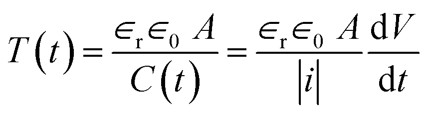

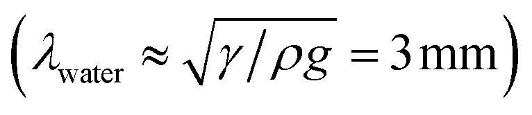 (γ and ρ being the surface tension and density of water and g is the acceleration due to gravity) so the effect of gravity could be safely neglected. In the absence of an external electric field, coalescence of aqueous drops occurs solely due to the Laplace pressure driven decrease in oil film thickness and that is why it takes a much longer time (∼600 s). With an applied voltage, the coalescence becomes much faster due to the added contribution of electrostatic pressure. Therefore one can write the total pressure difference (ΔP) between the two drops, which is responsible for oil film drainage, as: