
 Open Access Article
 This Open Access Article is licensed under a
 Creative Commons Attribution 3.0 Unported Licence
A polymer based and template-directed approach towards functional multidimensional micro-structured organic/inorganic hybrid materials†
C. G.
Schäfer
ab,
S.
Vowinkel
a,
G. P.
Hellmann
a,
T.
Herdt
b,
C.
Contiu
a,
J. J.
Schneider
*b and
M.
Gallei
*a
aErnst-Berl-Institut für Technische und Makromolekulare Chemie, Technische Universität Darmstadt, Alarich-Weiss-Str. 4, D-64287 Darmstadt, Germany. E-mail: m.gallei@mc.tu-darmstadt.de
bEduard-Zintl-Institut für Anorganische und Physikalische Chemie, Technische Universität Darmstadt, Alarich-Weiss-Str. 12, D-64287 Darmstadt, Germany. E-mail: joerg.schneider@ac.chemie.tu-darmstadt.de
First published on 30th July 2014
Abstract
The control over structure and function in hierarchically multidimensional materials based on hollow spheres, nanowires, nanorods, nanotubes, fibres, membranes or inverse opals with adjustable dimensions has gained considerable attention due to their tremendous potential for a wide variety of applications. Herein we describe convenient and efficient synthetic concepts for synthesis and processing of well-defined polymer-templated inorganic materials with 0D, 1D, 2D and 3D nano- and microstructures. In the first step, we describe universal methodologies for the controlled build-up of polymer-templated non-functional inorganic structures by taking advantage of lower dimensional structures such as core–shell particles or fibres. With this approach it is possible to obtain more sophisticated architectures such as 3D ordered macroporous (3DOM) materials after applying different procedures for organization, e.g. the powerful melt shear technique as well as novel double-templating strategies towards multidimensional carbon architectures. To prove the feasibility of our protocols established herein we have exemplarily applied these methods to the formation of functional inorganic high-temperature materials, such as silicon carbide (β-SiC) and yttria-stabilized zirconia (YSZ). The general pathways for the controlled build-up of nano- and micro-scaled structures based on polymer templates may thus provide a facile and versatile route to an even wider variety of organic/inorganic composite materials offering a wider range of future applications in the fields of catalysis, separation, sensors, optics, and biomedicine. Herein we show first examples of selected new material morphologies towards energy related issues, namely Li-ion battery applications and heterogeneous catalysis (selective ethanol oxidation).
1. Introduction
The concept of multifunctionality based on hierarchically ordered materials is a general concept in nature which has spurred intensive research among scientists over the last few decades.1 Current effort in the fields of nanoscience and nanotechnology for the development of multi-dimensional materials featuring nano-scaled functionalities to mimic these basic concepts from the artificial side is of growing interest. Such structures are capable of providing different responses, i.e. optical, electrical, magnetic, and chemical, on demand, meaning that they can be triggered by an external stimulus.2–5 From a materials point of view such multifunctional structures can either be hybrid structures e.g. a doped solid inorganic material or an organic/inorganic polymer containing different structurally diverse components which are intimately connected to each other. On the other hand and in contrast to those, in a composite structure organic, biological and/or different inorganic materials are composed together without intimate covalent binding between these individual components.The fabrication of hierarchically structured mesoporous materials by synthesis and combination of e.g. hollow spheres, nanowires, nanorods, nanotubes, fibres, membranes or 3D ordered macroporous (3DOM) materials such as inverse opals with adjustable dimensions has gained considerable attention due to their tremendous potential for various applications. Such materials and combinations thereof are highly promising candidates in the fields of catalysis, separation, sensors, optics, and biomedicine.2–8 As a feasible preparation route, different templating strategies have been applied for controlling the shape and size of the final materials after removal of the template structure.9–17 Especially hard templating is a versatile technique for the formation of hollow micro- and nanostructures.18 Furthermore, coating strategies have been extensively studied to further modify the template surfaces for introducing additional functionalities or for enhancing mechanical properties, chemical robustness or biocompatibility.19–21 Besides these different possibilities of creating defined material compositions using a templating approach, the utilization of templates with different morphologies (0D, 1D, 2D or 3D) allows us to tailor the nano-, micro- and macro-shape of the final material.
In this contribution different concepts for the synthesis of well-defined polymer-templated inorganic structures with a hierarchical nano/microstructure in different dimensions are presented. Firstly, two templates of submicroscopic dimensions are investigated for that purpose: polymer spheres (0D) and polymer fibres (1D). We took advantage of 0D spheres which were used to obtain internal architectures of 3D structures after applying different techniques of particle organization. The melt-shear technique will be in the focus to organize spherical templates. Furthermore, a general method for fibre coating and casting is applied forming porous layers or films (2D) after thermal treatment. The described general approaches for the preparation of well-defined non-functional silica and polymer templates are extended towards 0D, 1D, 2D and 3D carbon structures using novel double-templating approaches, and they are furthermore utilized in order to obtain functional inorganic materials, e.g. silicon carbide (β-SiC) and yttria-stabilized zirconia (YSZ). Both materials are accessible in a straightforward manner as ceramic membranes in macroscopic size. We have thus proven a general concept for the formation of structured organic/inorganic hybrid, pure carbon and highly functional inorganic materials with defined morphological hierarchy spanning a wider range of compositions. While the main purpose of this work is to illustrate the diversity of polymer-templated inorganic structures as a universal structure-building platform, we furthermore report on the potential of the materials described herein for energy related issues like heterogeneous catalysis (selective ethanol oxidation) and Li-ion batteries. For our approach presented herein, we envisage the future potential of these synthetic and technological methodologies to be adaptable to a variety of other functional materials which extends the diversity of synthetic pathways towards hierarchically structured materials in which their physical dimensions can be precisely controlled and well-defined samples can be tailored for respective advanced applications.
2. Experimental section
2.1 Materials and methods
Styrene, polystyrene (PS) 143 E and Disponil FES 27A were purchased from BASF SE, polymethyl methacrylate (PMMA) 7 N and methyl methacrylate (MMA) were obtained from Evonik Röhm GmbH and Dowfax 2A1 was obtained from Dow Chemicals. All other chemicals were purchased from Fluka, ABCR, Acros, VWR and Sigma Aldrich and used as received unless further mentioned. Prior to use in emulsion polymerisation protocols, stabilizers hydroquinone monomethylether and 4-tert-butylcatechol were removed from the monomers as follows. MMA was extracted with 1 mol L−1 sodium hydroxide solution in water, washed with water until it became neutral followed by drying with sodium sulfate. Styrene and acrylonitrile were distilled under reduced pressure. Allyl methacrylate (ALMA) was destabilized using the ion exchanger De-Hibit 200 (PolySciences Europe GmbH, Eppelheim).For electrospinning experiments a custom-built electrospinning setup consisting of three main components was used: a high voltage power supply, a system of a polymer syringe (5 mL) equipped with a stainless steel needle (0.8 × 40 mm) and an inserted copper electrode, representing the first electrode, and a vertically arranged stainless steel counter electrode (d = 5 cm), which serves as a substrate for the collection of the fibres.22,23
Scanning electron microscopy (SEM) was performed on a Philips XL30 FEG at an operating voltage of 5–25 kV. For studying the elemental composition, energy dispersive X-ray spectroscopy (EDX) with an EDX detector Apollo 40 SDD from EDAX was performed. Transmission electron microscopy (TEM) was performed on a Zeiss EM10 with an operating voltage of 60 kV. For high resolution transmission electron microscopy (HRTEM) and selected area electron diffraction (SAED) a FEI Technai F20 with an operating voltage of 200 kV was used.
2.2 Synthesis of microscopic PS spheres
Monodisperse PS spheres are synthesized by emulsifier-free emulsion polymerisation according to the literature.24 Under argon, a 1 L flask equipped with a stirrer and a reflux condenser is filled with 670 g deionized water at 75 °C and stirred at 300 rpm. After 60 min, the polymerisation is started by adding 75 g styrene and 0.5 g sodium peroxodisulfate (SPS). After 12 h, the polymerisation is completed. The synthesis yields monodisperse PS spheres with an average diameter of 790 (±12) nm as determined by TEM measurements.The resulting PS spheres are enlarged in a subsequent swelling polymerisation step similar to a process described in the literature.25 Under argon, a 1 L flask equipped with a stirrer and a reflux condenser is filled with 483.1 g of seed latex and stirred at 200 rpm. After 30 min a monomer emulsion consisting of 216.6 g water, 0.65 g Disponil FES 27A and 72.5 g styrene is added and stirred for the swelling procedure at 200 rpm under argon for 24 h. The mixture is then heated to 75 °C. After 45 min the polymerisation is initiated by continuous addition of a solution of 0.36 g SPS in 35.9 g water over 5 h. After an additional 60 min, the product is cooled to room temperature. The synthesis yields monodisperse PS spheres with an average diameter of 975 (±10) nm as determined by TEM measurements.
2.3 Synthesis of PMMA and PMMA/PSAN core–shell (CS) spheres
Under argon, a 1 L flask equipped with a stirrer and a reflux condenser is filled with a cold monomer emulsion consisting of 280 g deionized water, 0.40 g ALMA, 3.6 g MMA and 0.02 g sodium dodecylsulfate (SDS) at 75 °C and stirred at 200 rpm. The polymerisation is initiated by adding 0.050 g sodium bisulfite, 0.175 g SPS and 0.050 g sodium bisulfite in this sequence. After 10 min, a monomer emulsion consisting of 7.0 g ALMA, 70.0 g MMA, 0.23 g SDS, 0.22 g Dowfax 2A1, 0.4 g KOH and 90 g water is added continuously over 2 h. After 30 min the polymerisation is completed. The synthesis yields monodisperse PMMA spheres with an average diameter of 210 (±10) nm as determined by TEM measurements.The resulting PMMA spheres can subsequently be coated with a PSAN shell. For initiating the shell growth polymerisation, 0.03 g SPS are added to the PMMA core latex under argon at 75 °C and stirred at 200 rpm. After 15 min, a monomer emulsion consisting of 36 g styrene, 84 g acrylonitrile, 0.4 g SDS, 0.44 g Triton X-405 and 120 g water is added continuously over 4 h. After an additional 60 min of stirring, the dispersion is cooled to room temperature. The synthesis yields monodisperse PMMA/PSAN CS spheres with an average diameter of 300 (±15) nm as determined by TEM measurements.
2.4 Electrospinning of PS and PMMA fibres
Fibre fleeces of PMMA and PS are prepared by electrospinning according to the literature using a custom-built system.26 The fibres are electrospun from polymer solution, which is filled in the syringe of the setup and afterwards a voltage in the range of 5–30 kV is applied. Simultaneously, the solvent evaporates and the polymer fibres are deposited onto the counter electrode as dense fibre fleeces consisting of randomly stacked polymer fibres.PMMA fibres are electrospun from a 15 wt% PMMA solution in a mixture of acetone and dimethyl formamide (DMF) (60/40 w/w) at an electrode distance of 20 cm and a voltage of 30 kV. After 20 min of spinning time dense fleeces of PMMA fibres with an average fibre diameter of 790 (±240) nm as determined by SEM measurements are obtained.
PS fibres are electrospun from 16 wt% PS solution in a mixture of tetrahydrofuran (THF) and DMF (60/40 w/w) at an electrode distance of 25 cm and a voltage of 30 kV. After 20 min of spinning time, dense fleeces of PS fibres with an average diameter of 2.4 (±1.0) μm as determined by SEM measurements are obtained.
2.5 Synthesis of PS/silica CS spheres, silica hollow spheres and carbon hollow spheres
Monodisperse PS/silica CS spheres are prepared by a modified Stöber method from tetraethyl orthosilicate (TEOS) in ethanol.27 In order to make the PS spheres capable for growth of a silica shell, a plasma treatment process is used for functionalising the sphere surface.28 After separation of the PS spheres from their dispersion in water by centrifugation and subsequent drying at 50 °C, the spheres are transferred into a chamber of the plasma generator (Model Pico, Diener Electronic). After evacuation of the chamber to a residual pressure of 0.3 mbar, the samples are repeatedly treated with oxygen plasma generated at 20 W for 6 s. After plasma treatment, the PS spheres (0.29 g) are dispersed in a solution of 1.37 mL water, 1.5 mL ammonia (28–30 wt% solution in water) and 1 mL TEOS in 32.1 mL ethanol for intended coating with a silica shell at room temperature overnight. The synthesis yields PS/silica CS spheres with an average diameter of 1095 (±15) nm and a shell thickness of 60 nm as determined by TEM measurements.For the preparation of silica hollow spheres, the ethanolic dispersion of PS/silica CS spheres is dried at 60 °C in a vacuum followed by thermal treatment in a furnace at 550 °C under air for 2 h. By this procedure, a white powder of silica hollow spheres with an average diameter of 1090 (±15) as determined by TEM measurements is obtained.
For the preparation of carbon hollow spheres, the ethanolic dispersion of PS/silica CS spheres is dried at 60 °C in a vacuum followed by pyrolysis in a furnace at 750 °C under air for 2 h. The resulting silica/carbon hybrid spheres are etched in HF (40 wt% in water) for 3 days to remove the silica. By this method, a black powder of carbon hollow spheres with an average diameter of 975 (±10 nm) and a shell thickness of 50 nm as determined by TEM measurements is obtained.
2.6 Synthesis of PS/silica CS fibres and silica hollow fibres
Monodisperse PS/silica CS fibres are prepared by a modified Stöber method from TEOS in ethanol.27 In order to functionalize the PS fibres for growth of a silica shell, analogous to the previously described procedure for the particles, a plasma treatment process is used for functionalising the fibre surface. After drying the electrospun PS fibre fleece at 50 °C overnight, the fleece is transferred into a chamber of the plasma generator (Model Pico, Diener Electronic). After evacuating the chamber to a residual pressure of 0.3 mbar, the samples are treated several times with oxygen plasma generated at 20 W for 6 s. After functionalization, the PS fibre fleece (0.05 g) is transferred to a solution of 1.37 mL water, 1.5 mL ammonia (28–30 wt% solution in water) and 1 mL TEOS in 32.1 mL ethanol and the fibres are coated with a shell of silica at room temperature overnight. The synthesis yields a white fleece of PS/silica CS fibres with an average diameter of 2.9 (±0.5) μm and a shell thickness of 200 nm.For the preparation of silica hollow fibres the PS/silica CS fibre fleece is repeatedly washed with ethanol and dried at 50 °C in an oven. The fibres were thermally treated in a furnace at 750 °C under air for 4 h. A white fleece of silica hollow fibres with an average diameter of 1.9 (±0.5) μm as determined by SEM measurements is obtained.
2.7 Synthesis of silica and YSZ membrane with channel pores
Membranes with channel pores are prepared by an endotemplating technique from electrospun PMMA fibre fleeces by infiltration with sol–gel precursor solution. Therefore, a silica sol is prepared consisting of 6 mL TEOS, 4 mL ethanol, 3 mL water and 1 mL concentrated hydrochloric acid. After controlled aging at room temperature for 10 min, the sol–gel precursor solution is diluted with 14 mL ethanol and the sol is allowed to infiltrate into the electrospun polymer-template fibre fleece upon application by a spray-coating technique. The sol was sprayed to the horizontally stored slides as a fine aerosol using an airbrush gun (Agora-Tec GmbH, Schmalkalden). The obtained PMMA/silica composite sample is dried for 1 h under ambient conditions followed by heating in a furnace at 450 °C over 1 h to remove the majority of the polymer template, followed by final calcination at 450 °C under air for 4 h. A white film of silica membrane featuring defined channel pores is obtained.By applying exactly the same protocols as previously described, membranes with channel pores consisting of yttria-stabilized zirconia (Y2O3/ZrO2, YSZ) are produced by infiltration with Y2O3/ZrO2 sol which is prepared according to the literature.29 Therefore, an Y2O3/ZrO2 sol is prepared from 2.76 g ZrOCl2 × 8H2O, 0.58 g Y(NO3)3 × 5H2O (Zr/Y 0.84/0.16 mol mol−1), 0.75 g glycine, 10 mL water and 20 mL ethylene glycol. After controlled aging at 80 °C for 1 h, the sol–gel precursor solution is heated to 100 °C followed by cooling to room temperature. The sol is then allowed to infiltrate into the electrospun polymer-template fibre fleece upon application of a spray-coating technique. The obtained PMMA/YSZ composite sample is dried for 48 h at 50 °C under ambient conditions, heated in a furnace to 600 °C over 1 h in order to remove the majority of the polymer template, followed by final calcination at 600 °C for 4 h under air. A white film of YSZ membrane featuring channel pores is obtained.
2.8 Synthesis of carbon and SiC membrane with tubular structured pores
Membranes of carbon and SiC with tubular structured pores are prepared by a chemical vapour deposition (CVD) process from the silica membrane with channel pores. The as-synthesized silica membrane is placed in a CVD system and heated to 700 °C in a vacuum by induction heating using an electrical coil. Afterwards, propene is introduced for 15 min and carbon is deposited at the surface of the membrane and the pores by thermal decomposition of the carbon precursor at 700 °C.For the preparation of the carbon membrane featuring tubular structured pores, the resulting silica/carbon composite is etched in HF (40 wt% in water) for 3 days in order to completely remove the silica template. For final graphitization, the membrane is washed several times with ethanol, dried at 50 °C, and thermally treated at 1600 °C in a vacuum for 45 min. A black monolith of carbon membrane with hollow carbon fibres with an average diameter of 510 (±190) nm as determined by SEM measurements is obtained.
For the preparation of the SiC membrane featuring tubular structured pores, the silica/carbon composite is heated to 1600 °C in a vacuum, and allowed to react for 45 min yielding SiC. A greyish monolith of SiC membrane consisting of SiC tubes with an average diameter of 455 (±107) nm as determined by SEM measurements is obtained.
2.9 Preparation of PMMA colloidal crystal and silica 3DOM structure
A PMMA-based colloidal crystal is prepared from monodisperse PMMA spheres with an average diameter of 210 nm by vertical deposition on a glass slide similar to a process described in the literature.30Therefore, the glass substrates are deposited vertically in a beaker containing PMMA-particle dispersion (0.2 wt% in water). The solvent is allowed to evaporate slowly at a temperature of 50 °C over a period of 3–5 days while the samples are placed in a slight air stream. A porous colloidal crystal of PMMA spheres with a thickness of 10 μm showing a strong yellow reflection color is obtained.
For the preparation of a 3D ordered macroporous (3DOM) silica structure, the interstices are filled by an endotemplating technique by infiltration with a silica sol–gel precursor solution. The silica sol is prepared by mixing 6 mL TEOS, 4 mL ethanol, 3 mL water and 1 mL concentrated hydrochloric acid. After controlled aging at room temperature for 10 min, the sol–gel precursor solution is diluted with 14 mL ethanol and the sol is allowed to infiltrate into the polymer-template colloidal crystal upon application by a spray-coating technique. The obtained PMMA/silica composite sample is dried for 1 h under ambient conditions, heated in a furnace over 1 h to 450 °C in order to remove the majority of the polymer template, followed by final calcination at 450 °C for 4 h under air. A silica 3DOM structure revealing a strong blue reflection color is obtained.
2.10 Preparation of PMMA/PSAN colloidal crystal and carbon 3DOM structure
A PMMA/PSAN-based colloidal crystal is prepared from PMMA/PSAN CS spheres featuring an average diameter of 300 nm by using a melt-shear technique.31–33 In order to prepare a compact colloidal crystal, the sphere dispersion is dried at 40 °C under ambient air for several days. After drying, 5 g of the polymer powder is heated to 180 °C between the plates of a Collin 300E laboratory press, which are covered with PET foil. Then, melt flow is induced with a pressure of 250 bar. The melt is not confined in a cavity but it is allowed to flow freely sideways. After 3 min, the film is allowed to cool to room temperature. A compact colloidal crystal film of PMMA spheres embedded in a PSAN matrix revealing a yellow reflection color is obtained. Film disks typically have 150–250 μm thickness and a diameter of 12 cm.For the preparation of a 3DOM carbon structure, the PMMA/PSAN colloidal crystal is slowly heated to 400 °C over 1 h in order to remove the majority of the PMMA cores and to further cross-link the PSAN matrix, followed by final carbonization at 400 °C for 4 h under air. A black monolith of 3DOM carbon is obtained.
2.11 Synthesis of electrochemically active LiCoO2
100 mg of bis(η-1,5-cyclooctadiene)cobalt lithium is decomposed in a ceramic boat at 500 °C under argon (Ar flow: 200 sccm) for 1 h and finally oxidized by passing air for 1 h at the same temperature. This results in the formation of a black colored LiCoO2. The obtained material is characterized by XRD and is identical to that previously described.34,352.12 Electrochemical measurements
Electrochemical studies were carried out with a multichannel potentiostat VMP3 (Bio-Logic, France). Swagelok-type cells were assembled in an argon-filled dry box. The cathodes were prepared by mixing LiCoO2 with hollow carbon spheres with an average diameter of 975 nm and PVDF binder (ratio 80 wt%, 10 wt%, 10 wt%) respectively and were intimately mixed and ground in a mortar with N-methyl pyrrolidone (NMP, Sigma-Aldrich) as a solvent. The resulting mixture was deposited onto an Al-foil (13 mm in diameter) and dried at 120 °C under vacuum for ∼12 h. The electrodes contained about 3 mg of active compound. Lithium metal was used as an anode and the electrolyte was 1 M LiPF6 in ethylene carbonate–dimethyl carbonate (EC–DMC = 1/1 v/v). Glass microfibre separator (Whatman GF/A) was used between the anode and the cathode. The cathode is galvanostatically cycled between 2.5 and 4.2 V.2.13 Cu@SiO2 catalyst preparation
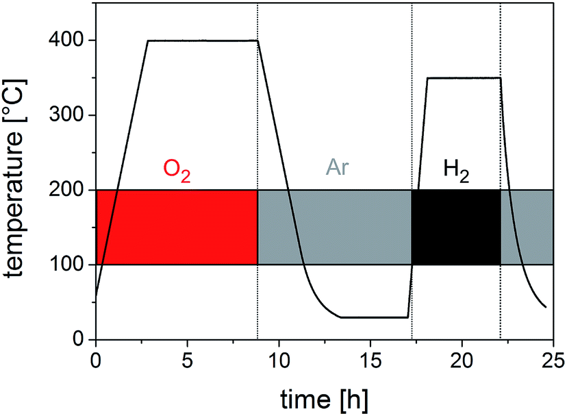
A silica-supported copper catalyst (Cu@SiO2) with a loading of 5 wt% Cu is prepared by impregnating 200 mg of dry silica membrane containing channel pores with 0.24 mL of an aqueous solution of Cu(NO3)2 (0.66 mol L−1) using a rotating pelletizing plate. After drying at 70 °C in a vacuum for 6 h, the catalyst is subsequently calcined in a quartz tube under O2 (21 vol%, argon carrier gas) at 400 °C for 6 h followed by final reduction under H2 (10 vol%, argon carrier gas) at 360 °C for 5 h.2.14 Catalytic measurements
The catalytic apparatus used consisted of three main parts: the gas dosing unit, the plug flow reactor and the connected online analytical unit. The gas dosing was performed using mass-flow controllers (Bronkhorst) and two stage gas saturators which enabled the enrichment of ethanol in the carrier gas flow. Partial oxidation of ethanol was performed in a plug flow reactor containing 10 mg of Cu@SiO2 catalyst in the temperature range between 130 °C and 500 °C. Calibration measurements were done before the catalytic reaction took place and are described elsewhere.36 Online analysis of the gaseous components at the reactor outlet was done with a quadrupole mass spectrometer (Inprocess Instruments, GAM 400). In order to obtain the startup phase of the catalyst prior to the temperature programmed (TP) reaction a reduction with H2 (6 vol%, argon carrier gas) at 400 °C was carried out. After the isothermal reduction the temperature was cooled to 140 °C and the TP experiments were carried out (6 vol% of ethanol and 3 vol% of O2, argon carrier gas, catalyst heating up to 500 °C at a heating rate of 10 K min−1). This procedure was performed overall three times (see Fig. S1†) to achieve steady state conditions and to stabilize the catalytic system, viz. activity and selectivity of ethanol to acetaldehyde.3. Results and discussion
The following chapter is divided into different sections introducing the universal methodologies for the generation of hierarchical microstructures. First, the basic synthesis technologies for uniform particles and fibres as well as state of the art template strategies are briefly discussed followed by introducing novel convenient polymer template-directed strategies and double-template approaches towards multidimensional micro-structured materials. After a more general section for the preparation of all the structures described herein, methods are applied to non-functional silica materials, which are furthermore used as templates for the preparation of carbon materials, such as hollow spheres and hollow fibres. In order to demonstrate the general applicability of the described template synthesis protocols, they are exemplarily transferred to other application oriented high-performance ceramics. Beyond these general synthesis protocols towards multidimensional architectures, the functional properties of the newly prepared carbon/silica materials with respect to energy related issues are presented (catalysis, Li-ion batteries).3.1 Microstructures derived from polymer spheres and fibres
Monodisperse polymer-based colloidal spheres are prepared by emulsion polymerisation of organic monomers in water. By this common method monodisperse submicroscopic spheres of adjustable sizes are formed. The key issue for monodispersity of corresponding spheres can be summarized by a fast nucleation stage, followed by a long stage of particle growth. This period can be prolonged by continuous addition of an organic monomer. In general, this convenient technique is capable of forming particles with adjustable average diameters of 50–800 nm. By applying sequenced emulsion polymerisation protocols, multi-phase structures can be prepared as well. If different monomers are sequentially polymerised in the same polymerisation system, the prevailing intolerance of the polymers leads to self-assembly: micro-phase-separated structures with fascinating internal architectures are formed. Within this contribution, particularly the core–shell (CS) architecture is of special interest. Here, a core of the first polymer is covered with a shell of the second polymer. By combination of emulsion polymerisation protocols and well-established sol–gel processes, organic/inorganic hybrid CS-spheres can be obtained. Therefore, polymer core particles are prepared by emulsion polymerisation and transferred to the sol–gel precursor solution, in which monodisperse particles are functionalized with an inorganic shell. In order to obtain 0D architectures, polymeric core spheres serve as templates for the inorganic precursor deposition. The resulting hybrid CS spheres can be converted into inorganic hollow sphere architectures simply by full thermal degradation of the polymer or by dissolution of the organic polymer core. This templating process is well-established and has already been applied for a variety of inorganic hollow spheres, e.g. SiO2, TiO2 and ZnO.37–40Due to the pristine polymer sphere structure, also more complex inorganic architectures are accessible. Monodisperse spheres feature the intrinsic capability to self-assemble into colloidal crystalline structures. Such colloidal crystals are 3D close-packed structures with a long-range order. Different routes for colloidal crystallization can be applied. Within this study, two of them were used: for porous colloidal crystals a rather simple drying process from dispersions of hard spheres is widely used. By this method of controlled drying, colloidal crystals of particle dispersions on flat substrates can be created. The hydrodynamic pressure during drying and the capillary forces of volatilizing dispersion medium provides controlled colloidal crystallization. Colvin et al. developed the method of vertical deposition,30 wherein the solvent of a colloidal dispersion is slowly evaporated inside a narrow vessel. Inside the vessel, a glass substrate is vertically deposited allowing the spheres to crystallize successively onto the substrate. With this technique, colloidal crystal areas of 1 cm2 size consisting of about 50 particle layers can be easily produced. However, problems occur by this method as prepared colloidal crystals are inherently porous and full of cracks. Such structures can be considered as multi-crystalline as they are neither compact nor mono-crystalline. A significantly improved method yielding porous 3D structures, which can be converted into compact 3D structures, is known as colloidal crystal templating. The basic concept of colloidal crystal templating is rather simple: the interstitial spaces of the air-filled colloidal crystals of spheres are infiltrated with a fluid precursor for the target material. This approach can be applied to, e.g., sol–gel solution, salt solution, CVD and electrochemical precursors. After template removal by calcination in the presence of oxygen, a porous inverse replica is obtained. The final inverse colloidal crystalline structure is referred to as a 3D ordered macroporous (3DOM) material. Recently, Aizenberg et al. developed an elegant method of vertical deposition enabling the generation of compact composite colloidal crystals via co-assembly of polymeric colloidal spheres and a silica sol–gel precursor solution.41,42 This route avoids the subsequent infiltration step and the accompanied cracking of the crystal structure. Subsequent removal of the colloidal crystal template by thermal decomposition generates mechanically stable 3DOM silica with minor defects and large crystal domains on the centimetre length scale.
The organization of suspended colloidal organic spheres under shear fields has attracted significant attention. Monodisperse particles arrange themselves in laminar flow fields: at low volume fractions strings were obtained while with high volume fractions stacked close-packed planes are accessible. Furthermore, such almost perfect structures can be produced in the flow fields of confined melts. The promising melt-shear organization technology, for which CS particles consisting of a rigid core and a surface-anchored meltable shell are essential, was developed over the last decade.31–33,43–45 In contrast to other methods of colloidal organization, self-supporting and crack-free films on the multi-metre scale can be produced. The melt-shear technique combines extrusion, rolling with subsequent edge-induced rotational shearing.45–47 CS spheres are heated between the plates of a press until a paste with high viscosity is achieved. Then, the molten mass is compressed with a constant force. During the uniaxial compression at elevated temperature, the molten mass flows radially and the cores arrange themselves in the flowing melt into stacked hexagonal layers resulting in a precise fcc arrangement of hard cores embedded in a matrix. The advantages of the melt-shear process can be highlighted as follows: first, the shear force generates a long-range order on a large scale and hence self-supporting crack-free colloidal crystal films, second, macroscopically oriented crystal monodomains emerge. With this fast and convenient method, large-scalable colloidal crystal films can be produced in series with thicknesses ranging from 0.1 to 1 mm. Films obtained are freestanding or attached to various substrates. We here expand this technique to hybrid particle architectures as feasible precursors for functional inorganic materials.
In Fig. 1 possible architectures obtained from spherical polymer templates are depicted. The pristine spheres (0D), which are monodisperse with regard to their diameters, can be converted (I) into CS particles. This process is known as exotemplating. Afterwards they can be converted (II) into hollow spheres. All spheres can self-assemble into colloidal crystals (3D) with a face-centered cubic (fcc) lattice. These well-ordered colloidal crystals come in two kinds: porous air-filled structures and compact crystals. Porous 3D structures are formed by controlled drying (III) of hard spheres. After crystallization the particles lay very close with a small contact area surrounded by air. Hence, colloidal crystals are highly porous and fragile, almost like powders. On the other side, compact colloidal crystals result from two other strategies: the porous structure can be converted into a compact colloidal crystal by an infiltration step (IV), which includes sol–gel precursor treatment and its solidification. This process is known as endotemplating. In more detail, the compact colloidal crystal can be prepared by melt-shearing from CS spheres consisting of a hard core and a meltable shell (V). At the end of the process, the shell provides the matrix between the embedded hard core particles. From these compact colloidal crystals 3DOM materials can be prepared as well after template removal (VI).
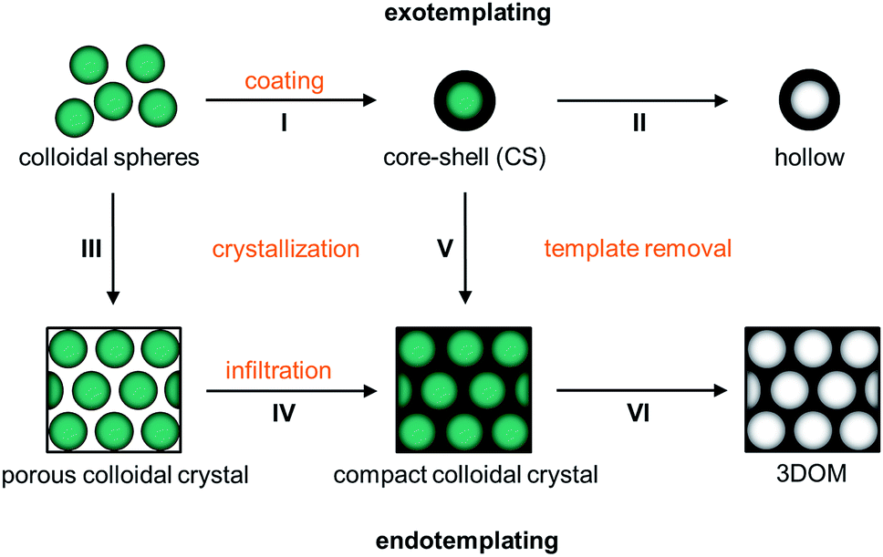 | ||
| Fig. 1 Scheme of the templating processes starting from monodisperse polymer spheres showing the individual topological transformation steps: the initial polymer sphere template can either be coated with a secondary material by step I creating a core–shell (CS) structure and hollow spheres are formed upon step II of template removal (exotemplating) or the spheres can be crystallized into a porous colloidal crystal by step III which is infiltrated with a secondary material by step IV to form a compact colloidal crystal followed by step VI of template removal providing a final 3DOM structure (endotemplating). More directly compact colloidal crystals are formed from CS spheres by step V of melt-crystallization where the shells provide a matrix between the cores followed by the transformation into 3DOM structure by step VI of template removal. | ||
Instead of spheres (0D), however, also fibres (1D) of submicroscopic diameters can be used as templates for the formation of microstructures. Microfibres of this kind are usually prepared by electrospinning, where polymer solutions or melts are spun under high voltage.22,23 Precisely controllable spin parameters provoke the targeted control to adjust the diameter, morphology and thickness of the spun fibres. Meanwhile solid fibres as well as tubes of various polymers are accessible by electrospinning.48 By this method, fleeces of randomly deposited stacked fibres can usually be produced that are feasible as a template material. There exist various methods to convey structures to these fibres and, however, the strategies are similar to those used for the spheres. Especially the processes of exo- and endotemplating can easily be transferred to fibres: first, the fibres can be coated after transferring to a sol–gel precursor solution (I in Fig. 2). When the native polymeric fibre underneath the coating is removed, the coating is first solidified and transferred into a green body and finally calcined which removes the polymer template completely resulting in all inorganic hollow fibres (II in Fig. 2). The described methodology including fibre coating and template removal is known as the tubes by fibre templates (TUFT) process and has been used for the production of hollow fibres of different oxides, e.g. SiO2, TiO2 and CeO2.49–51 In an alternative endo-templating process the interstices of the fibres can be infiltrated e.g. by spray coating with a precursor solution (III in Fig. 2). After solidification and template removal, this procedure leads to products with adjustable pore channels (IV in Fig. 2). The products obtained after controlled heating and final calcination are porous ceramic membranes. Similar approaches have already been applied to cellulose fibre templates to fabricate porous metal oxides after pyrolysis of the fibre template on heating,52 but to the best of our knowledge this method has not yet been applied to electrospun fibre fleeces. This method comprises major advantages for electrospun polymer fibres: pore size and thus the porosity of the resulting materials can be precisely controlled by a suitable choice of the template material and the deposition conditions already during the electrospinning process.
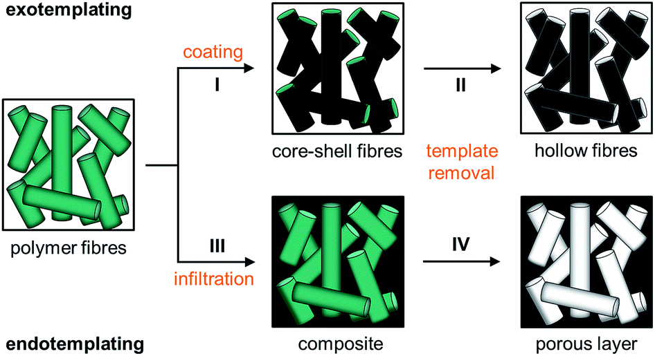 | ||
| Fig. 2 Scheme of the templating processes starting from polymer fibres showing the individual topological transformation steps: the initial polymer fibre template can either be coated with a secondary material by step I creating core–shell (CS) fibres and hollow fibres are formed upon step II of template removal (exotemplating) or the interstices of the fibres can be filled with a secondary material by step III of infiltration to form a composite structure followed by step VI of template removal finally providing a porous ceramic material (endotemplating). | ||
The combination of the aforementioned methods is first shown for silica structures which are subsequently transferred to carbon materials using novel double-templating approaches. As a proof of principle, we describe herein how chemically and morphologically well-defined micro-structured polymer/inorganic hybrid materials and therefrom multidimensional inorganic materials with high potential as functional hybrid materials and ceramics are accessible.
3.2 Spheres and hollow spheres (0D)
Utmost established studies deal with the synthesis of CS spheres featuring a polymer-based core and a silica shell. In particular, heterophase polymerisation techniques in combination with sol–gel processes have been found to be a feasible method.37,38 PS as an organic core material in PS/SiO2 CS particles can easily be removed by thermal treatment up to 550 °C or by dissolving the core material using an organic solvent to yield hollow silica spheres.For the preparation of hollow silica spheres described herein according to strategies I and II (Fig. 1) a combination of emulsion polymerisation and a sol–gel process was used. For the well-established Stöber process, silicic esters were hydrolysed in alcohols under base catalysis to form amorphous silica after condensation reaction. Starting from monomers, the condensation leads via branched oligomers and nanoseeds to nanospheres. Importantly, under suitable conditions for the Stöber process, nanospheres grow to monodisperse silica particles. In order to functionalise further the polymer particles with silica, a transfer of the polymer spheres from their aqueous dispersion to the sol–gel precursor in water–alcohol solution is required. Again, the presence of silica oligomers is crucial as these species is first absorbed on the surface before a condensed silica network is formed. Hence, a dense closed shell can be obtained by growth of such seeds by adding a monomer and oligomer. A major obstacle to this transfer is the rather high polarity of the silica oligomers. As the oligomers are very polar due to the silanol and deprotonated silanol groups they will not get adsorbed onto the unpolar surface of the polymer spheres. To overcome the problem of separated silica growth during the Stöber process, also referred to as the 2nd nucleation process, the surface of the polymer template has to be tuned to match the polarity of silica.
In order to produce a smooth silica shell and hollow silica spheres, microscopic polystyrene (PS) particles were synthesized as polymer templates. After subsequent functionalization, the PS particles were further functionalised with silica shells and converted into silica hollow spheres after removal of the polymeric template by thermal treatment. Submicroscopic PS spheres were accessible by emulsifier-free emulsion polymerisation.24 The synthesis yielded monodisperse 780 nm particles that were subsequently enlarged in a second step of swelling by adding a monomer emulsion of styrene in water.25 After complete monomer absorption, the swollen spheres were polymerised at elevated temperature by the continuous addition of a radical initiator. As can be seen from Fig. 3a, the synthesis yielded monodisperse spheres with an average diameter of 975 nm. In order to compatibilize the polymer particle surface for silica attachment and growth of silica shells, PS particles were isolated by centrifugation and subsequently hydrophilised by oxygen plasma treatment several times according to the method of Kim et al.28 For introducing the silica shell to the PS particles, particles were redispersed in ethanol containing tetraethyl orthosilicate (TEOS), ammonia and water for hydrolysis and condensation of the precursor. After complete condensation of TEOS, the resulting CS structure was characterized by using TEM of ultrathin sample sections. The corresponding TEM images (Fig. 3b) prove the preparation of the CS structure. Due to the cutting of the sample with a diamond knife the structure is slightly distorted and the corresponding spheres appear deformed in TEM images. Remarkably, the smooth silica shells of 60 nm thickness are clearly visible out of these images after careful sample preparation (Fig. 3b). Hollow silica spheres could be obtained by removing the PS template simply by heating. The hybrid PS/silica particles were heated to 550 °C in the presence of oxygen. As a result, the hollow silica spheres (Fig. 3c) retained their integral structure after calcination due to the dense and smooth silica shell. The EDX spectrum in Fig. S2† shows the peaks of silica without further impurities. Obviously, heating to 550 °C is sufficient to remove the PS cores and to prepare perfect silica hollow spheres.
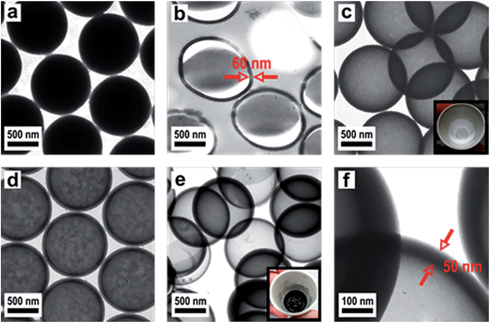 | ||
| Fig. 3 TEM images of (a) bare PS spheres, (b) ultrathin section of silica-coated PS CS spheres, (c) silica hollow spheres after calcination at 550 °C (inset: photograph showing white powder of silica hollow spheres), (d) silica/carbon hybrid spheres after calcination at 750 °C, (e) carbon hollow spheres after etching with HF (inset: photograph showing black powder of carbon hollow spheres) and (f) higher magnification showing the shell thickness of carbon hollow spheres. | ||
However, while heating the PS particles to 750 °C, a carbonized residue remained and silica hollow spheres containing pyrolysed carbon were formed (Fig. 3d). The pyrolysis of PS has been studied in detail under a variety of reaction conditions wherein particularly the influence of the temperature on the composition of the reaction products has been observed.53 Based on these studies PS decomposes according to the depolymerisation mechanism, whose main product at temperatures below 550 °C is the styrene monomer, dimer and trimer. At temperatures above 750 °C carbon is formed by the incomplete combustion of the aromatic compounds.54 The temperature-dependent difference between the complete pyrolysis of PS at lower temperatures and the starting carbonization at higher temperatures was investigated for the silica/carbon hollow spheres presented herein by using TGA (Fig. S3 and S4†) and C/O elemental analysis (Table S5†). A comparison of TGA measurements in Fig. S3 and S4† as well as results from C/O elemental analysis of the products in Table S5† demonstrates that below 750 °C PS was completely removed and silica hollow spheres were formed, while heating above 750 °C, a carbonized residue remained and silica/carbon hybrid spheres were formed. The carbonization of PS inside the silica thus led to novel products which were highly feasible: the silica spheres could simply be etched with hydrofluoric acid in a subsequent step yielding monodisperse hollow carbon microspheres with a shell thickness of 50 nm (Fig. 3e and f). The EDX spectrum of the corresponding calcined and etched particles (Fig. S6†) revealed that hollow spheres composed of pure carbon were formed. The carbon produced by incomplete pyrolysis of PS was deposited inside the silica shells forming a uniform carbon layer. In this particular case, the silica shell now serves as a template for carbon. Especially noticeable is the fact that the spheres were still intact even after template removal. Our novel double-templating approach presented herein represents a unique and powerful method opening access to even and uniform carbon hollow spheres starting from monodisperse PS spherical templates. The well-structured hybrid materials were proven for feasible conversion through a combination of carbonization and template removal into carbon structure while maintaining its overall morphology. It has already been shown that hollow carbons show promising potential as electrode materials in lithium containing batteries.54,55 Therefore we investigated the performance of the hollow carbon spheres (Fig. 3e and f) as conductive fillers for Li-cathode electrodes. For this purpose, we synthesized nanoscaled LiCoO2 as an electroactive cathode material from the single source precursor bis(η-1,5-cyclooctadiene)cobalt–lithium by thermal decomposition and controlled calcination as reported previously by us.35 The obtained nanoscaled LiCoO2 was then intimately ground and mixed together with the hollow carbon spheres (Fig. 3e and f) acting as a conducting material. Fig. 4a shows a SEM image revealing the morphology of the LiCoO2/hollow carbon sphere material. The composite material consists of homogeneously intermixed components.
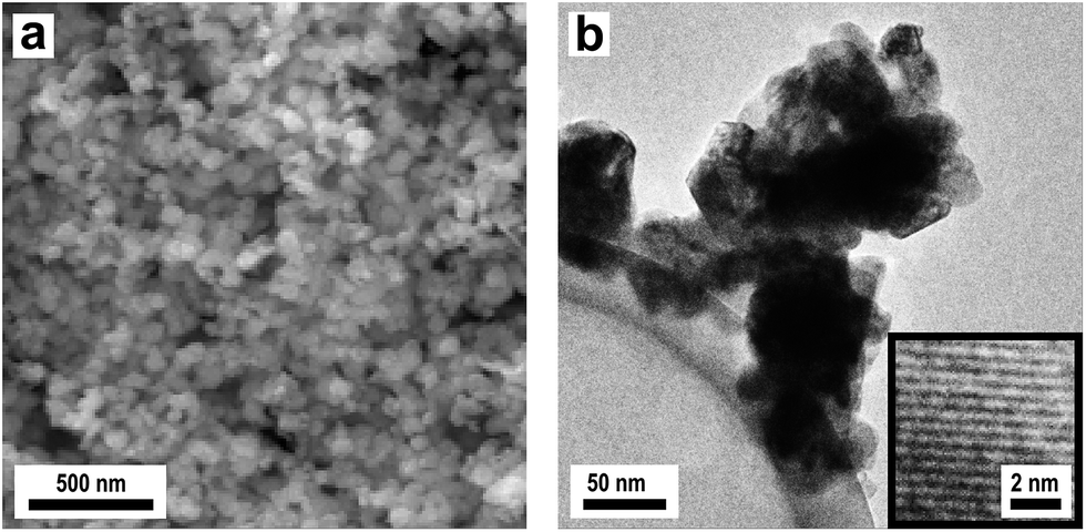 | ||
| Fig. 4 (a) SEM image showing the electroactive LiCoO2/carbon hollow sphere material used as a Li intercalation cathode material and (b) TEM image of the nanocrystalline LiCoO2 particles tethered onto the spherical carbon sphere surface; the inset shows a HRTEM image revealing the nanocrystalline nature of the LiCoO2 particles. | ||
The TEM image in Fig. 4b shows the intimate attachment of the LiCoO2 nanoparticles on the carbon shell surface of the hollow carbon particles providing an inherent and good electrical contact between both components. The high-resolution transmission electron microscopy (HRTEM) inset in Fig. 4b proves the nanocrystalline nature of the deposited electroactive LiCoO2 material. As can be seen from Fig. 4b, the carbon capsules provide a thick and dense continuous carbon wall (about 50 nm) which allows for a high electrical conductivity. Finally, an additional binder was added to ensure good long term adhesion of the active materials in the assembled cell setup (ratio: 80/10/10 w/w/w LiCoO2/carbon/binder). The electrochemical cycling behavior (charging/discharging) is shown in Fig. 5. The observed charge/discharge cycles of assembled cells differed significantly if all composite cathode materials were intimately ground before cell assembly or when assembled without intense mixing and grinding before. This fact can be attributed to a better contact of the active materials within the final battery cathode. Devices with ground and without ground material compositions however showed a comparable and quite typical steep capacity loss during the first two cycles due to the well-known formation of the solid electrode interface (SEI) layer.
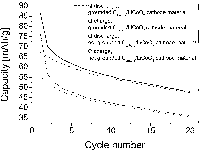 | ||
| Fig. 5 Charge and discharge capacity as a function of the cycle number of LiCoO2/spherical carbon cathode material. The notation “ground” denotes samples in which all cathode components were intimately ground and mixed mechanically prior to electrochemical cathode cell preparation. The notation “not ground” denotes samples which are just mixed together without further grinding. | ||
After the first two cycles the initial capacity of 70 mA h g−1 decreases to about 55 mA h g−1 after 20 cycles for the cathode composed of the ground material and from 55 to 36 mA h g−1 for the not ground LiCoO2/carbon shell cathode material. Interestingly, the spherical carbon shell material showed the same ability acting as a good conductive component as the commercial Super P@Li from TIMCAL used in a previous study with the same precursor under the same conditions.34,35 The overall capacity loss observed was 1.05 mA g−1 per cycle (for ground and not ground material) and thus it corresponds nicely to values observed previously for the LiCoO2 active material on commercial TIMCAL.34,35
It should be mentioned that previous studies focussed on independent methods for the fabrication of spherical hollow carbon precursors. From a synthetic point of view silica/polymer particle endotemplating approaches are valuable methods for this purpose.55,56 These techniques have proven that it is possible to adjust the inner diameter, the shell thickness and the morphology of such spherical hollow carbon spheres which has allowed their application in gas-adsorption,57 and catalysis.58
3.3 Fibres and hollow fibres (1D)
In the next step hollow silica fibres were prepared according to strategies I and II (Fig. 2) analogous to the coating process described above for PS particles. Therefore, microscopic PS fibres were prepared by electrospinning.26 A SEM image of a fleece of randomly stacked PS fibres, spun from PS solution in THF/DMF, is shown in Fig. 6a. Thick fleeces of uniform PS fibres with an average diameter of 2.4 μm could be obtained. The PS fibres were dried and subsequently hydrophilised in a rf-oxygen plasma, in order to match the polarity of the Stöber silica, before the fibres were coated with a silica shell in the Stöber process (in the same way as for the polymer particles). For this purpose the polymer fibres were incorporated into ethanol in which the silica shell was condensed in situ to the fibre surface from the TEOS precursor. In contrast to coating of PS spheres a significant amount of free silica particles was formed, so the fleeces had to be purified after silica deposition by washing with ethanol. After drying, the PS/silica CS composite fibres were slowly heated in the presence of oxygen in order to complete the silica formation and to stabilize the structure further. Simultaneously, the inorganic coating of the composite material is transferred into a green body followed by final calcination at 750 °C which removes the PS template completely and results in the formation of hollow fibres (Fig. 6b). A comparison of Fig. 6a and b demonstrates that the fleece-like superstructure remained fully intact over all preparation steps, whereas a hollow fibre structure was generated on the microscopic level. As can be seen from the SEM image (Fig. 6c), the wall of the silica tubes with a thickness of approximately 200 nm is composed of intimately nucleated individual silica particles. The EDX spectrum in Fig. S7† proves that silica was formed. The HRTEM image in Fig. 6d reveals that the silica tubes are composed of amorphous silica.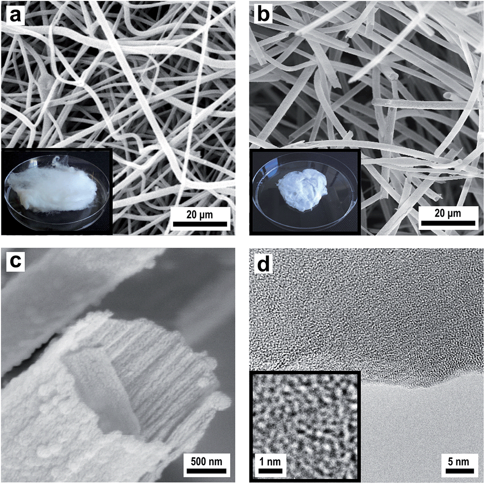 | ||
| Fig. 6 SEM images of (a) bare PS fibres (inset: photograph of the electrospun PS fibre fleece), (b) silica hollow fibres after calcination at 750 °C (inset: photograph of the silica hollow fibre fleece) and (c) higher magnification showing the morphology of silica hollow fibres. (d) HRTEM image showing the amorphous structure of silica walls. | ||
It should be mentioned that our synthesis strategy described herein is similar to the techniques previously reported but together with the new results presented herein allows a most current overview of techniques and methods of polymer templating strategies.49,51 Therefore, in the following section we will introduce a novel double templating approach starting from such electrospun fiber templates which will significantly widen the scope of so far established protocols in order to obtain new well-defined tubular-structured carbon-based membranes.
3.4 Porous layers with channel and tubular structured pores (2D)
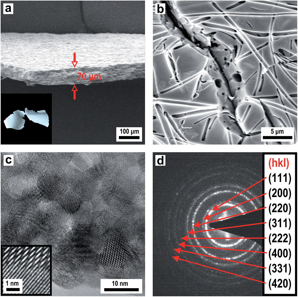
For the preparation of porous membranes featuring channel and tubular structured pores according to strategies III and IV (Fig. 2), fibre fleeces were infiltrated with a sol–gel precursor solution for silica. As a template, fleeces of PMMA fibres were used as PMMA completely depolymerises in air at temperatures higher than 215 °C. Hence, PMMA is another suitable template which can be removed completely under mild conditions. A SEM image of a fleece of PMMA fibres, spun from PMMA solution in acetone–DMF (Fig. 7a), revealed uniform fibres with an average diameter of about 800 nm. Porous layers from these fibre fleeces were prepared by infiltration via spray coating with an ethanolic sol–gel precursor solution of TEOS containing a small amount of hydrochloric acid. The precursor solution was allowed to stand for 10 minutes in order to start the condensation process prior to spraying this silica sol as an aerosol. Obviously, the increasing degree of infiltration was evident in the increase of transparency, which indicated that more and more interstices between individual polymer fibres were filled with the precursor solution. After drying, the infiltrated fibre fleeces were slowly heated to 450 °C in air whereby the silica precursor condensed completely forming a green body ceramic and the PMMA template was burnt out resulting in the formation of a membrane like structure in which the formed dense ceramic is randomly pervaded with pores. This material thus represents a negative replica of the initial polymeric fibrous morphology. Fig. 7b presents a SEM image of a silica membrane with tubular structured pores with an average pore diameter of 600 nm. The SEM image in Fig. 7c proves the overall morphology of a macroscopically sized porous membrane of silica with a uniform thickness of 70 μm. The obtained microstructure of the silica material is completely amorphous as revealed by HRTEM (Fig. 7d) while the corresponding EDX spectrum shown in Fig. S8† shows only signals for silicon and oxygen. The overall templating process employed herein should certainly allow for a broader applicability while allowing us to employ different inorganic sols in this process.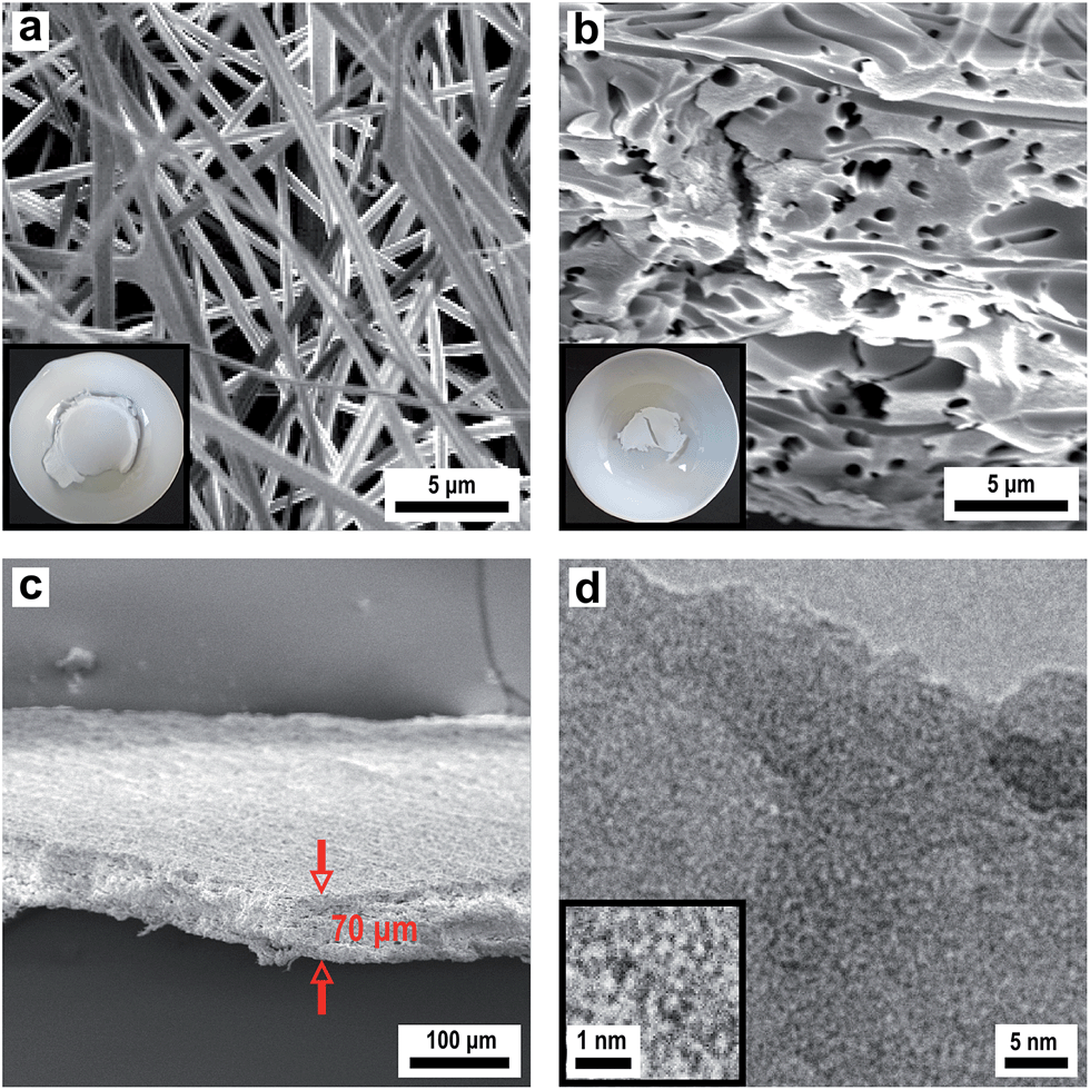 | ||
| Fig. 7 SEM images of (a) bare PMMA fibres (inset: photograph of the electrospun PMMA fibre fleece), (b) cross-section of a negative silica replica with channel pores after calcination at 450 °C (inset: photograph of a porous silica replica layer) and (c) lower magnification showing the thickness of the porous silica membrane. (d) HRTEM image showing the amorphous structure of the silica matrix. | ||
To prove the functionality of the porous silica membrane obtained by the replicating process we first generated nanoscaled Cu particles on the silica membrane by an impregnation/calcination/reduction process using Cu(NO3)2 as a precursor and subsequently employed this material (termed Cu@SiO2 hybrid material) in a catalytic reaction. Fig. 8 shows the temperature vs. time profile for the silica-supported Cu catalyst (Cu@SiO2) generation from the precursor onto the silica membrane.
 | ||
| Fig. 8 Calcination and reduction profile for the generation of Cu nanoparticles from the Cu(NO3)2 precursor on a microporous silica membrane (Cu@SiO2). | ||
Characterization of the obtained Cu@SiO2 hybrid material by XRD revealed the formation of nanoscaled Cu (see Fig. S9†). Besides metallic Cu no other copper containing phases are present in the initial catalyst. Characterization by TEM (Fig. 9a and b) reveals a homogeneous deposition of the Cu particles on the porous silica. However, the metallic Cu particles show a broad size distribution with particle diameters in the range between 50 and 100 nm.
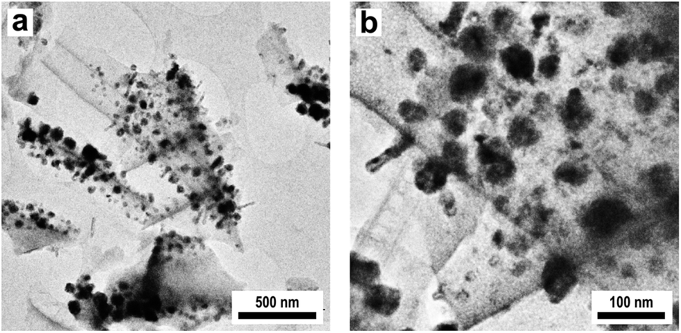 | ||
| Fig. 9 TEM images of Cu nanoparticles on a microporous silica membrane at (a) low and (b) higher magnification deposited by a three step impregnation/calcination/reduction process using Cu(NO3)2 as a precursor. | ||
The Cu@SiO2 system was then tested for its catalytic performance in the partial oxidation of ethanol to acetaldehyde (eqn (1)):
 | (1) |
Studies on the oxidation of methanol and ethanol on Cu(110) showed that Cu(0) was especially active when it was partially oxidized to a substoichiometric composition.59,60 Nanoscaled Cu(I) and Cu(II) oxides were also active, when dispersed on ZnO or MWCNTs.36 The catalyst activity and selectivity of our Cu@microporous silica membrane material towards different products is given in Fig. 10. Fig. 11 shows the conversion rate, selectivity and yield of the catalyst system with respect to acetaldehyde. Remarkably, in the temperature-programmed (TP)-reaction experiment an abrupt increase in the catalyst activity is observed at about 375 °C.
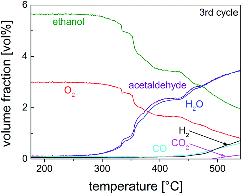 | ||
| Fig. 10 Volume fraction as a function of reaction temperature for the third cycle of the TP partial oxidation reaction of ethanol on 10 mg of pre-reduced Cu@SiO2 catalyst (EtOH–O2 = 2/1 mol/mol). | ||
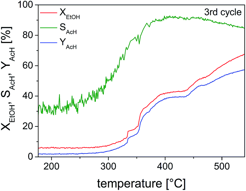 | ||
| Fig. 11 Selectivity of acetaldehyde (SAcH), conversion percentage of ethanol (XEtOH) and yield of acetaldehyde (YAcH) as a function of temperature for the TP-reaction of ethanol on 10 mg of pre-reduced Cu@SiO2 catalyst. | ||
Indeed, for partial methanol oxidation it is well known that such an enhanced catalyst activity coincidences with transformation of the oxidic phase to the suboxidic/metallic phase as observed by the O K- and Cu L3-NEXAFS spectra.61 Thus, it is very reasonable to assume a similar phase change for the originated zerovalent Cu particles deposited on the porous silica membranes (Cu@SiO2 material). Indeed we have already shown that pure Cu(0) species is not active towards oxidation of ethanol.36 However, in the presence of oxygen, Cu2O besides Cu(0), which remains still present, is formed and presenting the active catalyst.36
We also studied the deposition of carbon within the pores of the silica membranes via a chemical vapour deposition (CVD) process to obtain porous carbon based membranes. Here the porous silica serves as a template for carbon deposition. As a precursor for carbon, propene was used which is decomposed at elevated temperature. At 700 °C, the carbon was deposited from the gas-phase covering the surface of the channels (Fig. 12b). After carbon deposition, the silica matrix is etched with HF completely leaving a dense fleece of hollow carbon fibres (Fig. 12c). A comparison of Fig. 12a and c confirms that the macroscopic structure of the porous silica layer as well as the microscopic pore structure remained intact. It is well known that carbon deposition from propene at 700 °C leads to low graphitization. Therefore after removal of the silica template, the as obtained porous carbon structure was subsequently graphitized at 1600 °C to increase the degree of graphitization. The corresponding EDX spectrum is shown in Fig. S10† which only shows the signal for carbon. Fig. 12d shows a porous carbon membrane with a uniform thickness of 70 μm that is composed of hollow carbon fibres. The TEM image of these hollow carbon fibres revealed an average wall thickness of about 100 nm (Fig. 12e). The HRTEM image shows the turbostratic multi-layered graphitic structure with its orientation along the tube axis (Fig. 12f).
 | ||
| Fig. 12 SEM images of the (a) silica membrane with channel pores (inset: photograph of the silica membrane), (b) silica/carbon composite after carbon deposition via CVD at 700 °C, (c) fleece of carbon hollow fibres after etching with HF and subsequent graphitization at 1600 °C (inset: photograph of the carbon hollow fibre fleece) and (d) lower magnification showing the thickness of the carbon membrane with tubular structured pores. (e) TEM image of carbon hollow fibres showing the wall thickness and (f) HRTEM image showing the turbostratic multi-layered graphitic structure along the tube axis. | ||
By the synthesis protocol described herein we were able to produce well-defined carbon membranes containing tubular-structured pores. This was achieved by starting from PMMA fibre templates by applying a double-templating approach as a structure-guiding platform. As a result, porous carbon was formed featuring a fibrous superstructure. Based on their unique microstructure we assume the great potential of the carbon membranes prepared herein for future applications such as e.g. gas sensors or water purification materials.
3.5 Colloidal crystals and 3DOM materials (3D)
Monodisperse spheres were assembled to form colloidal crystals according to strategies III and V (Fig. 1), either by controlled drying of their dispersion, which leads to porous colloidal crystals, or by shearing their melt, which leads to compact colloidal crystals. After infiltration of the porous structure with fluidic sol–gel precursor solution according to strategy IV (Fig. 1) and subsequent template removal of the corresponding compact colloidal crystals, the structures were converted into 3DOM solids (VI in Fig. 1). All of these crystalline structures feature Bragg reflection colours evidencing the homogeneous domain sizes. For this purpose, submicroscopic PMMA spheres were synthesized by seeded and stepwise emulsion polymerisation. Firstly, the core size was adjusted by using emulsion polymerisation protocols to obtain PMMA particles of 210 nm size which could be proven by TEM investigations (Fig. 13a). Moreover, it was necessary to cross-link the PMMA particles sufficiently by the addition of bifunctional allyl methacrylate (ALMA) to keep their shape integer over all preparation steps. These monodisperse PMMA particles were used to prepare colloidal crystals by the method of vertical deposition (IV in Fig. 1). A glass slide was therefore vertically immersed into the diluted aqueous dispersion of the polymer particles. The dispersion was then left to dry at 50 °C for several days and the spheres deposited onto the slide accompanied by crystallization. As can be seen from the SEM image (Fig. 13b), the spheres crystallized very nicely and the fcc lattice was oriented such that its hexagonal (111) plane covers the slide. By this method, layers of about 50 planes were obtained, so the overall film thickness was approximately 10 μm. Problems occur with these colloidal crystals that they are inherently porous and full of cracks as already mentioned above. However, optical properties were only slightly affected by the cracks of the crystals, but the mechanical stability was low due to the highly porous texture. Already slight abrasion can destroy the structure. If taken with care, the PMMA colloidal crystal structure can be infiltrated with a freshly prepared silica sol–gel solution of ethanol, TEOS, HCl and water which can be spray-cast into the structure. Similar to the procedure described for the infiltration of PMMA fibres, the increasing transparency of the structure was evident, which again indicated that these were well wetted by the silica precursors. After drying, the structure was slowly heated to 450 °C in air, whereby the silica precursor was condensed to provide a stable matrix while simultaneously removing the PMMA spheres yielding a so-called inverse colloidal crystal replica. This procedure turned the porous colloidal crystal into a 3DOM silica structure. As can be seen from the SEM image in Fig. 13c, the local crystal structure of ordered air pores embedded in the silica matrix is almost perfectly aligned and the inverted 3DOM structure reproduces the fcc lattice of the polymer template almost completely. The corresponding EDX spectrum is presented in Fig. S11† showing signals for silicon and oxygen. In each pore of the structure, three connecting channels to the deeper pores can be seen which are formed from the contact points of PMMA spheres in the colloidal crystal template.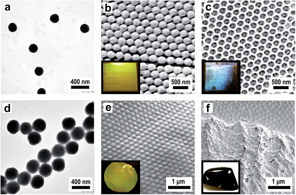 | ||
| Fig. 13 (a) TEM image of bare PMMA spheres, (b) SEM image of PMMA porous colloidal crystals showing the surface-parallel hexagonally arranged (111) plane (inset: photograph of a PMMA colloidal crystal showing strong yellow reflection color) and SEM image of the silica inverted 3DOM structure after calcination at 450 °C (inset: photograph of 3DOM silica showing strong blue reflection color). (d) TEM image of PMMA/PSAN CS spheres, (e) SEM image of the compact colloidal crystalline structure of PMMA/PSAN CS spheres showing the surface parallel (111) plane of PMMA spheres embedded in the PSAN matrix (inset: photograph of a PMMA/PSAN colloidal crystal revealing strong yellow reflection color) and (f) SEM image of the cross-section of carbon 3DOM structure after carbonization at 400 °C (inset photograph of monolithic 3DOM carbon). | ||
The vast majority of 3DOM structures were accessible by multi-step processes, which involve (self)assembly of colloidal spheres into colloidal crystals, followed by infiltration of the structure with precursor solution and removing the colloidal crystal template by dissolution or thermal decomposition. By using this technique, various 3DOM structures have already been fabricated, whose structural and compositional diversity has recently been highlighted by Stein et al.62 Similar conformal structures consisting of porous carbon can be obtained as a result of colloidal crystal infiltration with different carbon precursors and subsequent template removal.63,64 3DOM carbons are promising candidates for various applications and their potential in applications such as lithium-ion batteries, catalysis and hydrogen storage has already been proven.65 However, the multi-step approach towards 3DOM carbons has several drawbacks: small-sized, fragile and cracked carbon structures often featuring an ill-defined composition were often obtained, which greatly affects the materials properties and hence limits their technological potential.
In our approach, compact, stable and monocrystalline colloidal crystals were obtained by the method of melt-shear (V in Fig. 1). This technique relies on the fact that monodisperse particles always tend to crystallize under shear. This ordering effect of shear is particularly strong in melts of core–shell (CS) particles that are usually composed of a cross-linked, rigid PS core and a surface-anchored meltable polyacrylate shell. For this process, the cross-linked PMMA spheres depicted in Fig. 13a were functionalized with a meltable shell, with the intrinsic capability for subsequent carbonization. Concurrently, PMMA can easily be removed to form a 3DOM carbon structure. The main obstacle of the thermal degradation of the cores is that the softening and flowing of the matrix must be prevented during pyrolysis of the matrix to form a highly ordered 3DOM structure of pyrolytic carbon. For the preparation of compact colloidal crystals in the melt flow process, however, this is a basic prerequisite. To overcome that problem, stabilization of the structure was achieved by cross-linking the matrix during the pyrolysis by using CS spheres with cores made of cross-linked PMMA and shells made of styrene–acrylonitrile resin (PSAN) with high acrylonitrile content. From polyacrylonitrile (PAN) it is known that conjugated unsaturated carbon-rich polymers are formed by intramolecular cross-linking during oxidative thermal treatment at temperatures of 200–300 °C.66,67 Due to the stability of the pre-carbonized polymers, PAN can be completely carbonized in the absence of oxygen by further heat treatment at 400–1200 °C, without the loss of the superstructure. This advantage is used in industrial grade processes for the production of high-quality carbon fibres and films. In addition, Tamai et al. could already produce disordered carbon structures by pyrolysis of PSAN spheres composed of a styrene-rich core and acrylonitrile-rich shell.68 At temperatures between 400 and 1000 °C, the decomposition of PS, the cross-linking of PAN and formation of carbon structures of the spheres took place.
CS spheres with cross-linked rigid cores and surface-anchored PSAN shells were synthesized using semi-continuous and stepwise emulsion polymerisation. As cores, the cross-linked PMMA particles shown in Fig. 13a were used and acrylonitrile and styrene in a ratio of 70/30 (w/w) were continuously added to obtain the matrix-forming meltable PSAN shell. The outer shell was partially grafted to the cores due to the cross-linking agent containing cores. Here, we took advantage of the PSAN shell to generate compact colloidal crystals of PMMA spheres embedded in a PSAN matrix with the intrinsic capability for subsequent carbonization reaction. This feature enabled one to process the spheres at temperatures lower than the ceiling temperature of the cores. The controlled build-up of the CS spheres was verified by TEM investigations. Comparison of TEM images of PMMA cores in Fig. 13a and PMMA/PSAN CS spheres in Fig. 13d clearly shows that the particles were enlarged from 210 to 300 nm. The growth of the spheres was in excellent agreement with expectations proving that monodisperse CS spheres consisting of a PMMA core and a 45 nm thick PSAN shell were formed. The shell consisted of PS30AN70 revealing a glass transition temperature of 120 °C. Hence, the CS particles had the consistency of a hard solid at room temperature enabling the material to flow in the press after melting at 180 °C. For the melt-shear process the coagulated and dried particles were melted and then forced in a press to flow outwards between the plates, whereby they were strongly sheared and crystallized nicely. This led to compact colloidal crystal disks with a diameter of 12 cm revealing an excellent monocrystal quality in which the fcc lattice is uniformly oriented in the radial direction. The disks could be prepared with 0.1–1 mm thickness, small or large, free or on substrates. But nevertheless the PMMA cores were able to maintain their shape during the melt-shear process. In this process, spheres were continuously deposited forming arranged layers of the (111) planes, parallelly aligned to the sample surface. The precise arrangement of the surface parallel (111) planes could be seen in SEM investigations of the corresponding film samples (Fig. 13e). PMMA cores, precisely arranged in hexagonal layers of the (111) plane, embedded in the PSAN matrix are evidenced. Although this film was prepared by melt-shear processing at T = 180 °C, i.e. above the glass transition of the PMMA cores, particles have not been deformed. Thus obtained highly ordered colloidal-crystalline structures could be stabilized in a subsequent cross-linking and carbonization step, leading to 3DOM carbon structures. The corresponding EDX spectrum is shown in Fig. S12† which only shows the signal for carbon. Fig. 13f shows the SEM image of the film after carbonization at 400 °C. In the areas in which PMMA particles were placed, ordered air pores were visible after carbonization. The colloidal crystalline superstructure of the PMMA-PSAN CS particles could therefore be completely converted into porous 3DOM carbon in one simple step.
3.6 Micro-structured high temperature ceramics
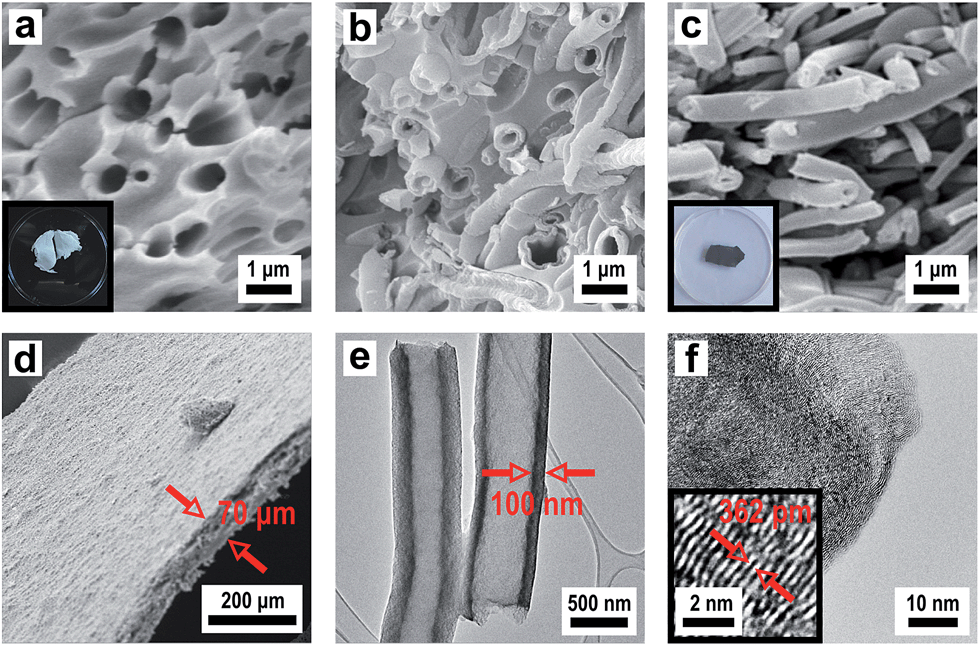
The described template synthesis protocols, which have been designed for silica and carbon structures, can even be transferred to other application oriented high-performance ceramics which have potential e.g. as ion conducting or high-temperature membranes. Yttria-stabilized zirconia (YSZ) is an interesting candidate for a variety of applications in solid state ionics such as oxygen sensors69 or fuel cell membranes70 because it has the ability to allow oxygen ions to move through the host structure at high temperatures. This high ionic conductivity makes it one of the most useful electro-ceramics. There is also growing interest on high-performance silicon carbide ceramics which are widely used in high-temperature/-voltage semiconductor electronics because its high thermal conductivity, high electrical breakdown strength and reasonably high electron mobility make it more promising than silicon for high-powered devices requiring high-temperature operation.71As a precursor for YSZ (ZrO2/Y2O3) with an exact composition of (ZrO2)0.84/(YO1.5)0.16, ZrOCl2 and Y(NO3)3 were used in an appropriate stoichiometric ratio of 0.84/0.16 (mol/mol). The thus prepared sol–gel precursor solution in ethylene glycol was sprayed as an aerosol onto a PMMA fibre mat. For removing ethylene glycol the composite was dried for several days in an oven at 50 °C before the obtained film was slowly heated to 600 °C in air to allow for formation of the green body ceramic which is then converted to the final ceramic material. Fig. 14a presents an SEM image of a porous YSZ membrane with a uniform thickness of 70 μm. As described before, the PMMA fleece structure (Fig. 7a) was decomposed after final calcination leaving a porous membrane with irregular pore channels representing the negative replica of the polymeric fibrous structure (Fig. 14b). The HRTEM image in Fig. 14c proves a polycrystalline layer of YSZ and the EDX spectrum in Fig. S13† shows only a very small remainder of carbon. The selected area electron diffraction (SAED) pattern demonstrates the high crystallinity of the obtained material (Fig. 14d). The YSZ phase corresponds to the cubic ZrO2 structure (Fm![[3 with combining macron]](https://www.rsc.org/images/entities/char_0033_0304.gif) m). The YSZ membrane is of polycrystalline nature consisting of small crystallites with a diameter of 5–10 nm.
m). The YSZ membrane is of polycrystalline nature consisting of small crystallites with a diameter of 5–10 nm.
 | ||
| Fig. 14 SEM images of (a) the YSZ membrane after calcination at 600 °C showing the thickness of the porous layer (inset: photograph of the YSZ membrane) and (b) higher magnification of the surface and cross-section of the YSZ membrane with irregular channel pores representing a negative replica of the polymeric fibrous structure. (c) HRTEM image showing the polycrystalline structure of the YSZ matrix (inset: superimposed Moire pattern of overlaid crystallites) and (d) SAED pattern of YSZ corresponding to the cubic ZrO2 structure. | ||
In another example how those porous silica membranes obtained by the template technique can be employed in a unique manner we have studied a modified Acheson type process for the synthesis of silicon carbide (eqn (2)):
 | (2) |
We employed the previously described silica/carbon composite membrane (see Fig. 12b) and heated it under vacuum to 1600 °C. This results in formation of β-SiC, which is the stable phase of SiC formed below 2000 °C,72 while keeping the morphology of the material intact. Again a porous ceramic with a thickness of 70 μm is formed (Fig. 15a) which is in accordance with the thickness of the electrospun polymer fleece used as a template. Fig. 15b shows a SEM image of the obtained hollow SiC fibres after conversion in the Acheson type process. A comparison of Fig. 12b and 15b demonstrates that the silica matrix is completely degraded after the thermal conversion at 1600 °C. The fleece type structure containing a channel like pore system composed of hollow fibres is retained. The TEM and HRTEM images (Fig. 15c and d) prove the highly crystalline nature of the SiC with a fibre diameter of around 500 nm and a tube wall thickness of around 200 nm. The HRTEM image as well as the EDX spectrum revealed a crystalline β-SiC composition of the tube walls (Fig. 15 and S14†). To summarize our approach represents a unique method for obtaining porous, macroscopically sized SiC membranes starting from a polymeric/inorganic hybrid material and converting that by a solid state reaction into β-SiC while maintaining its overall morphology.
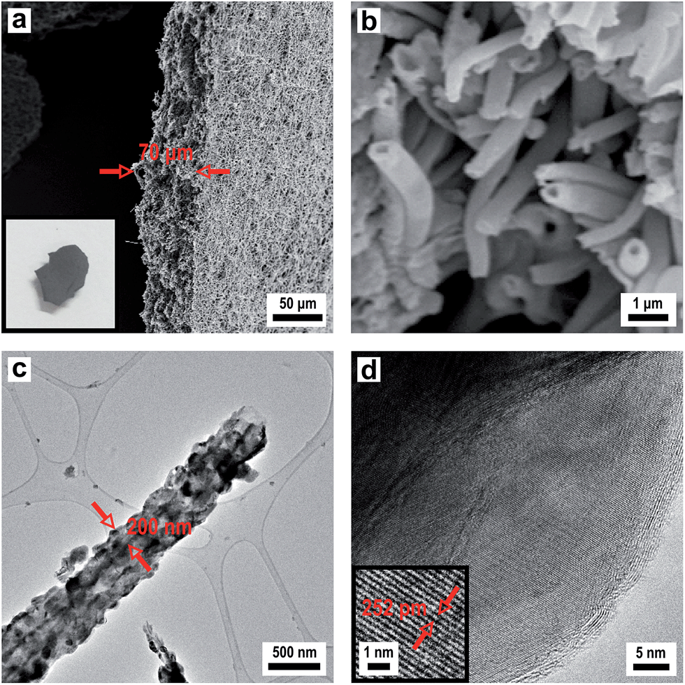 | ||
| Fig. 15 SEM images of (a) β-SiC membrane after thermal conversion of the silica/carbon hybrid structure at 1600 °C showing the thickness of the porous layer (inset: photograph of the SiC membrane) and (b) higher magnification of the cross-section of the β-SiC membrane with tubular structured pores representing a negative replica of the channel like pore system of the silica membrane. (c) TEM image of a SiC hollow fibre showing the morphology and thickness of the β-SiC hollow fibre walls and (d) HRTEM image revealing a crystalline β-SiC composition of the tube walls. | ||
4. Conclusions
In this contribution, we have presented efficient synthetic concepts for the synthesis of well-defined polymer-templated inorganic structures with a hierarchical 0D, 1D, 2D and 3D nano/microstructure. Structures of lower dimensions such as polymeric core–shell particles and fibres were incorporated and arranged into hierarchical composite materials with 2D or 3D architectures such as membranes, inorganic fibrous mats or 3DOM structures. This approach allows excellent control over their chemical composition as well as structural integrity during all processing steps. It has been proven that the explored methodologies leading to the polymer-based template structures are of wider applicability and thus are highly feasible for the formation of functional and multidimensional inorganic structures. The synthetic strategies and protocols developed herein have been exemplarily applied to the formation of functional inorganic materials, such as silicon carbide (β-SiC) and yttria-stabilized zirconia (YSZ), emphasizing indeed the generality of the presented concepts. The general pathways for the controlled build-up of nano- and micro-scaled structures based on polymer templates may thus provide a facile and versatile route to an even larger variety of organic/inorganic materials offering a wide range of possible applications in the fields of catalysis, separation, sensors, optics, and biomedicine. Exemplarily we have shown the applicability of the newly obtained materials in heterogeneous catalysis (partial ethanol oxidation) and energy applications (Li-ion batteries).Acknowledgements
The authors acknowledge technical support of Dr Jörg Engstler and Dipl. Ing. T. Heinlein (TEM and HRTEM support through the ERC-TU1 grant). MG and CGS thank Claudia Fasel (Department of Materials Science, TU Darmstadt) for performing the C/O elemental analysis. CC acknowledges technical advice during the catalysis experiments by Dr Alfons Drochner. The authors thank Prof. W. Ensinger (Department of Materials Science, TU Darmstadt) for providing the sputter coater used for SEM sample preparation. CGS and MG are supported by the LOEWE program and the cluster network SOFT CONTROL funded by the state of Hesse.Notes and references
- L. Christodoulou and J. D. Venables, JOM, 2003, 55, 39–45 CrossRef.
- M. E. Davis, Nature, 2002, 417, 813–821 CrossRef CAS PubMed.
- C. Burda, X. Chen, R. Narayanan and M. A. El-Sayed, Chem. Rev., 2005, 105, 1025–1102 CrossRef CAS PubMed.
- Y. Zhao and L. Jiang, Adv. Mater., 2009, 21, 3621–3638 CrossRef CAS.
- D. V. Talapin, J.-S. Lee, M. V. Kovalenko and E. V. Shevchenko, Chem. Rev., 2010, 110, 389–458 CrossRef CAS PubMed.
- G. M. Whitesides, Small, 2005, 1, 172–179 CrossRef CAS PubMed.
- Y. Piao, A. Burns, J. Kim, U. Wiesner and T. Hyeon, Adv. Funct. Mater., 2008, 18, 3745–3758 CrossRef CAS.
- S. Kaur, M. Gallei and E. Ionescu, Adv. Polym. Sci., 2014 DOI:10.1007/12_2014_282.
- F. Schüth and W. Schmidt, Adv. Mater., 2002, 14, 629–638 CrossRef.
- A. Stein, Adv. Mater., 2003, 15, 763–775 CrossRef CAS.
- T. Shimizu, M. Masuda and H. Minamikawa, Chem. Rev., 2005, 105, 1401–1443 CrossRef CAS PubMed.
- A. Thomas, F. Goettmann and M. Antonietti, Chem. Mater., 2008, 20, 738–755 CrossRef CAS.
- M. Llusar and C. Sanchez, Chem. Mater., 2008, 20, 782–820 CrossRef CAS.
- J. K. Sahoo, M. N. Tahir, A. Yella, T. D. Schladt, S. Pfeiffer, B. Nakhjavan, E. Mugnaioli, U. Kolb and W. Tremel, Chem. Mater., 2011, 23, 3534–3539 CrossRef CAS.
- R. K. Joshi and J. J. Schneider, Chem. Soc. Rev., 2012, 41, 5285–5312 RSC.
- L. Yang, Z. Wang, Y. Ji, J. Wang and G. Xue, Macromolecules, 2014, 47, 1749–1756 CrossRef CAS.
- D. Scheid, G. Cherkashinin, E. Ionescu and M. Gallei, Langmuir, 2014, 30, 1204–1209 CrossRef CAS PubMed.
- X. W. Lou, L. A. Archer and Z. Yang, Adv. Mater., 2008, 20, 3987–4019 CrossRef CAS.
- R. A. Caruso and M. Antonietti, Chem. Mater., 2001, 13, 3272–3282 CrossRef CAS.
- G. J. d. A. A. Soler-Illia, C. Sanchez, B. Lebeau and J. Patarin, Chem. Rev., 2002, 102, 4093–4138 CrossRef PubMed.
- C. Sanchez, C. Boissière, D. Grosso, C. Laberty and L. Nicole, Chem. Mater., 2008, 20, 682–737 CrossRef CAS.
- A. Greiner and J. H. Wendorff, Angew. Chem., 2007, 119, 5770–5805 CrossRef.
- S. Agarwal, A. Greiner and J. H. Wendorff, Adv. Funct. Mater., 2009, 19, 2863–2879 CrossRef CAS.
- J. W. Goodwin, J. Hearn, C. C. Ho and R. H. Ottewill, Colloid Polym. Sci., 1974, 252, 464–471 CAS.
- W. Wohlleben, F. W. Bartels, M. Boyle and R. J. Leyrer, Langmuir, 2008, 24, 5627–5635 CrossRef CAS PubMed.
- S. Megelski, J. S. Stephens, D. B. Chase and J. F. Rabolt, Macromolecules, 2002, 35, 8456–8466 CrossRef CAS.
- C. Graf and A. v. Blaaderen, Langmuir, 2002, 18, 524–534 CrossRef CAS.
- H. Li, C. S. Ha and I. Kim, Langmuir, 2008, 24, 10552–10556 CrossRef CAS PubMed.
- C. C. Chen, M. M. Nasrallah and H. U. Anderson, Solid State Ionics, 1994, 70, 101–108 CrossRef.
- P. Jiang, J. F. Bertone, K. S. Hwang and V. L. Colvin, Chem. Mater., 1999, 11, 2132–2140 CrossRef CAS.
- T. Ruhl and G. P. Hellmann, Macromol. Chem. Phys., 2001, 202, 3502–3505 CrossRef CAS.
- C. G. Schäfer, M. Gallei, J. T. Zahn, J. Engelhardt, G. P. Hellmann and M. Rehahn, Chem. Mater., 2013, 25, 2309–2318 CrossRef.
- C. G. Schäfer, B. Viel, G. P. Hellmann, M. Rehahn and M. Gallei, ACS Appl. Mater. Interfaces, 2013, 5, 10623–10632 Search PubMed.
- A. D. Roberts, X. Li and H. Zhang, Chem. Soc. Rev., 2014, 43, 4341–4356 RSC.
- J. P. Khanderi and J. J. Schneider, Eur. J. Inorg. Chem., 2010, 4591–4594 CrossRef CAS.
- J. Khanderi, C. Contiu, J. Engstler, R. C. Hoffmann, J. J. Schneider, A. Drochner and H. Vogel, Nanoscale, 2011, 3, 1102–1112 RSC.
- M. Chen, L. Wu, S. Zhou and B. You, Adv. Mater., 2006, 18, 801–806 CrossRef CAS.
- L. Zhang, M. D'Acunzi, M. Kappl, G. K. Auernhammer and D. Vollmer, Langmuir, 2009, 25, 2711–2717 CrossRef CAS PubMed.
- X. Cheng, M. Chen, L. Wu and G. Gu, Langmuir, 2006, 22, 3858–3863 CrossRef CAS PubMed.
- Z. Deng, M. Chen, G. Gu and L. Wu, J. Phys. Chem. B, 2008, 112, 16–22 CrossRef CAS PubMed.
- B. Hatton, L. Mishchenko, S. Davis, K. H. Sandhage and J. Aizenberg, Proc. Natl. Acad. Sci. U. S. A., 2010, 107, 10354–10359 CrossRef CAS PubMed.
- Y. Vasquez, M. Kolle, L. Mishchenko, B. D. Hatton and J. Aizenberg, ACS Photonics, 2014, 1, 53–60 CrossRef CAS.
- T. Ruhl, P. Spahn and G. P. Hellmann, Polymer, 2003, 44, 7625–7634 CrossRef CAS.
- O. L. J. Pursiainen, J. J. Baumberg, H. Winkler, B. Viel, P. Spahn and T. Ruhl, Adv. Mater., 2008, 20, 1484–1487 CrossRef CAS.
- C. G. Schäfer, D. A. Smolin, G. P. Hellmann and M. Gallei, Langmuir, 2013, 29, 11275–11283 CrossRef PubMed.
- C. E. Finlayson, P. Spahn, D. R. Snoswell, G. Yates, A. Kontogeorgos, A. I. Haines, G. P. Hellmann and J. J. Baumberg, Adv. Mater., 2011, 23, 1540–15444 CrossRef CAS PubMed.
- A. I. Haines, C. E. Finlayson, D. R. Snoswell, P. Spahn, G. P. Hellmann and J. J. Baumberg, Adv. Mater., 2012, 24, OP305–OP308 CrossRef CAS PubMed.
- D. Li and Y. Xia, Adv. Mater., 2004, 16, 1151–1170 CrossRef CAS.
- J. Patzsch and J. J. Schneider, Dalton Trans., 2013, 42, 1451–1460 RSC.
- R. A. Caruso, J. H. Schattka and A. Greiner, Adv. Mater., 2001, 13, 1577–1579 CrossRef CAS.
- J. J. Schneider, M. Naumann, C. Schäfer, A. Brandner, H. J. Hofmann and P. Claus, Beilstein J. Nanotechnol., 2011, 2, 776–784 CrossRef CAS PubMed.
- A. Thomas and M. Antonetti, Adv. Funct. Mater., 2003, 13, 763–766 CrossRef CAS.
- T. Faravelli, M. Pinciroli, F. Pisano, G. Bozzano, M. Dente and E. Ranzi, J. Anal. Appl. Pyrolysis, 2001, 60, 103–121 CrossRef CAS.
- J. Wang, Y. Levendis, H. Richter, J. Howard and J. Carlson, Environ. Sci. Technol., 2001, 35, 3541–3552 CrossRef CAS PubMed.
- F. Su, X. S. Zhao, Y. Wang, L. Wang and J. Y. Lee, J. Mater. Chem., 2006, 16, 4413–4419 RSC.
- R. J. White, K. Tauer, M. Antonietti and M.-M. Titirici, J. Am. Chem. Soc., 2010, 132, 17360–17363 CrossRef CAS PubMed.
- S. Feng, W. Li, Q. Shi, Y. Li, J. Chen, Y. Ling, A. M. Asiri and D. Zhao, Chem. Commun., 2014, 50, 329–331 RSC.
- X. Fang, J. Zang, X. Wang, M.-S. Zheng and N. Zheng, J. Mater. Chem. A, 2014, 2, 6191–6197 CAS.
- E. Wachs and J. Madix, J. Catal., 1978, 53, 208–227 CrossRef.
- E. Wachs and J. Madix, Appl. Surf. Sci., 1978, 1, 303–328 CrossRef.
- A. Knop-Gericke, M. Hävecker, T. Schedel-Niedirg and R. Schlögl, Top. Catal., 2001, 15, 27–34 CrossRef CAS.
- A. Stein, B. E. Wilson and S. G. Rudisill, Chem. Soc. Rev., 2013, 42, 2763–2803 RSC.
- T. N. Hoheisel, S. Schrettl, R. Szilluweit and H. Frauenrath, Angew. Chem., Int. Ed., 2010, 49, 6496–6515 CrossRef CAS PubMed.
- A. Stein, Z. Wang and M. A. Fierke, Adv. Mater., 2009, 21, 265–293 CrossRef CAS.
- B. Fang, J. H. Kim, M.-S. Kim and J.-S. Yu, Acc. Chem. Res., 2013, 46, 1397–1406 CrossRef CAS PubMed.
- C. L. Renschler, A. P. Sylwester and L. V. Salgado, J. Mater. Res., 1989, 4, 452–457 CrossRef CAS.
- J. Pospisil, M. Samoc and J. Zieba, Eur. Polym. J., 1998, 34, 899–904 CrossRef CAS.
- H. Tamai, T. Sumi and H. Yasuda, J. Colloid Interface Sci., 1996, 177, 325–328 CrossRef CAS.
- R. Ramamoorthy, P. K. Dutta and S. A. Akbar, J. Mater. Sci., 2003, 38, 4271–4282 CrossRef CAS.
- B. C. H. Steele and A. Heinzel, Nature, 2001, 414, 345–352 CrossRef CAS PubMed.
- M. Bhatnagar and B. J. Baliga, IEEE Trans. Electron Devices, 1993, 40, 645–655 CrossRef CAS.
- A. F. Hollemann and E. Wiberg, Lehrbuch der Anorganischen Chemie, W. de Gruyter, Berlin, 1995 Search PubMed.
Footnote |
| † Electronic supplementary information (ESI) available: Temperature program of the TP catalysis experiments (S1), EDX spectra of all materials prepared (S2, S6–S8 and S10–S14), TGA of PS/silica CS spheres (S3 and S4), C/O elemental analysis of silica and silica/carbon hybrid spheres (S5) and XRD of the Cu@SiO2 catalyst. See DOI: 10.1039/c4tc00633j |
| This journal is © The Royal Society of Chemistry 2014 |