 Open Access Article
Creative Commons Attribution 3.0 Unported Licence
A cobalt layer deposition study: Dicobaltatetrahedranes as convenient MOCVD precursor systems
C.
Georgi
a,
A.
Hildebrandt
a,
T.
Waechtler
b,
S. E.
Schulz
b,
T.
Gessner
b and
H.
Lang
*a
aTechnische Universität Chemnitz, Faculty of Natural Sciences, Institute of Chemistry, Inorganic Chemistry, 09107 Chemnitz, Germany. E-mail: heinrich.lang@chemie.tu-chemnitz.de; Fax: +49-371-531-21219
bFraunhofer Institute for Electronic Nano Systems (ENAS), Technologie-Campus 3, 09126 Chemnitz, Germany
First published on 14th March 2014
Abstract
Low melting or liquid cobalt(0) MOCVD precursors of type [Co2(CO)6(η2-RC![[triple bond, length as m-dash]](https://www.rsc.org/images/entities/char_e002.gif) CR′)] (R = H, R′ = (CH3)3Si, nC4H9, nC5H11, nC6H13, nC7H15; R = nC3H7, R′ = (CH3)3Si, CH3; R = R′ = C2H5, (CH3)3Si) have been prepared by the reaction of the appropriate alkynes with Co2(CO)8. Variation of the substituents at the C,C triple bond allowed the study of their influence on the thermal behaviour and vapour pressure. These measurements showed that the cobalt(0) precursors are suitable for application within the MOCVD (Metal–Organic Chemical Vapour Deposition) process. Decomposing deposition of the cobalt precursors was realized in a home-built vertical cold-wall CVD reactor under mild conditions without any addition of co-reactants. The obtained dense and conformal cobalt layers have been characterized by SEM, EDX and XPS measurements. Depending on the precursor applied, pure cobalt films (96.7% Co) or mixtures of cobalt, carbon and cobalt oxide with varying composition with layer thicknesses of 35–90 nm were formed.
CR′)] (R = H, R′ = (CH3)3Si, nC4H9, nC5H11, nC6H13, nC7H15; R = nC3H7, R′ = (CH3)3Si, CH3; R = R′ = C2H5, (CH3)3Si) have been prepared by the reaction of the appropriate alkynes with Co2(CO)8. Variation of the substituents at the C,C triple bond allowed the study of their influence on the thermal behaviour and vapour pressure. These measurements showed that the cobalt(0) precursors are suitable for application within the MOCVD (Metal–Organic Chemical Vapour Deposition) process. Decomposing deposition of the cobalt precursors was realized in a home-built vertical cold-wall CVD reactor under mild conditions without any addition of co-reactants. The obtained dense and conformal cobalt layers have been characterized by SEM, EDX and XPS measurements. Depending on the precursor applied, pure cobalt films (96.7% Co) or mixtures of cobalt, carbon and cobalt oxide with varying composition with layer thicknesses of 35–90 nm were formed.
Introduction
During the last decade the deposition of thin Co layers has gained considerable attention, due to their application, for example, as antibacterial coatings,1 in magnetic information storage2 and sensor systems,3 as well as catalyst material for the growth of carbon nanotubes.4 Especially in the light of the discovery of giant magnetoresistance (GMR) in multilayer structures, cobalt film formation has been studied with increasing efforts.5–9 The generation of such layered materials requires the deposition of thin films of cobalt, which could be achieved by traditional inorganic CVD (Chemical Vapour Deposition),10,11 sputtering,12 electron-beam evaporation13,14 and metal–organic (MO)CVD15–18 techniques. Within these studies, CVD has been shown to be a promising methodology for cobalt layer formation, since uniform coatings without ion-induced radiation damage were formed in a highly controlled manner.19 Furthermore, MOCVD provides lower deposition temperatures compared to classic inorganic CVD processes, due to the fragility of the cobalt–carbon bonds. However, the number of reports concerning cobalt CVD using organometallic precursor materials is very limited, especially Co(0) compounds are rather scarce.The deposition of thin metallic cobalt layers has been performed in previous work using, for example, Co2(CO)8,15,16,18,20–22 [Co(η5-C5H5)2],18 [Co(acac)2]23,24 and [Co(tBuNC(Me)NEt)2]25 as suitable precursors. However, those precursor systems are solids, which is unfavourable in processing and handling. Known liquid precursors such as [Co(η5-C5H5)(CO)2]16,18 and [Co(CO)3(NO)]26–29 exhibit the disadvantage of only producing uniform cobalt layers at high substrate temperatures (360–480 °C).28,30,31 Even when low substrate temperatures are applied as shown by Jeon et al. on the example of [Co2(CO)6(η2-HC![[triple bond, length as m-dash]](https://www.rsc.org/images/entities/char_e002.gif) C–C(CH3)3)] (150 °C, H2)32 the addition of reactive gases26–29 or plasma33,34 is required for cobalt depositions. These are rather harsh conditions that limit the scope of applicable substrates.
C–C(CH3)3)] (150 °C, H2)32 the addition of reactive gases26–29 or plasma33,34 is required for cobalt depositions. These are rather harsh conditions that limit the scope of applicable substrates.
Herein, we present the application of a series of dicobaltatetrahedranes of general composition [Co2(CO)6(η2-RC![[triple bond, length as m-dash]](https://www.rsc.org/images/entities/char_e002.gif) CR′)] (R = H, R′ = (CH3)3Si, nC4H9, nC5H11, nC6H13, nC7H15; R = nC3H7, R′ = (CH3)3Si, CH3; R = R′ = C2H5, (CH3)3Si) as CVD precursors for the deposition of thin cobalt layers in a home-built CVD reactor. These materials promise to be low melting precursors that will not require any addition of reactive gases during the deposition process. Within the series of compounds described, the substituents R and R′ have systematically been varied to investigate the influence of those modifications on the physical properties, such as the melting point, the vapour pressure and the combustion process.
CR′)] (R = H, R′ = (CH3)3Si, nC4H9, nC5H11, nC6H13, nC7H15; R = nC3H7, R′ = (CH3)3Si, CH3; R = R′ = C2H5, (CH3)3Si) as CVD precursors for the deposition of thin cobalt layers in a home-built CVD reactor. These materials promise to be low melting precursors that will not require any addition of reactive gases during the deposition process. Within the series of compounds described, the substituents R and R′ have systematically been varied to investigate the influence of those modifications on the physical properties, such as the melting point, the vapour pressure and the combustion process.
Results and discussions
Dicobaltatetrahedranes 3a–i have been synthesized according to published reaction procedures35–37 which are modified to increase selectivity and yield. In this respect, dicobaltoctacarbonyl 1 was reacted with alkynes 2a–i in n-hexane at ambient temperature for 2 h (Scheme 1). The resulting tetrahedranes could be obtained in excellent yields between 89 and 93% (Experimental section).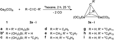 | ||
| Scheme 1 Reaction of 1 with alkynes 2a–i forming dicobaltatetrahedranes 3a–i. *Previously published.38 | ||
Compounds 3a–i have been characterized by elemental analysis, 1H NMR and IR spectroscopy. Furthermore, the thermal behaviour of 3a–i has been studied by thermogravimetric (TG) measurements as well as determination of the vapour pressure.
1H NMR spectroscopy of compounds 3b, 3f–i showed that the signal for the acetylenic proton is shifted from 2.35 (2b) and 1.92–1.93 ppm (2f–i) to 6.38 (3b) and 6.01 ppm (3f–i), respectively. Furthermore, the coordination of the alkynes to the Co2(CO)6 building block could be monitored by the shift of the carbonylic stretching vibration from 2068, 2041, 2024 and 1992 cm−1 in Co2CO8 (ref. 39) to 2084–2091, 2042–2049, 2009–2016 and 1967–1975 in 3a–i as well as the disappearance of the stretching vibration for the μ-bridging carbonyls at 1860 cm−1 (Experimental section).
Vapour pressure measurements
Vapour pressure measurements have been carried out to obtain information about the volatility of the appropriate organometallic cobalt compounds 3a–i. The vapour pressure measurements within this work were performed as described previously40 using a TGA (Thermogravimetric Analysis) system with a horizontal balance. These measurements allowed the determination of the Antoine parameters which are summarized in Table 1.| Compd | lg![[thin space (1/6-em)]](https://www.rsc.org/images/entities/char_2009.gif) p [Pa] = A − B/T p [Pa] = A − B/T![[thin space (1/6-em)]](https://www.rsc.org/images/entities/char_2009.gif) a a |
R 2 | |
|---|---|---|---|
| A | B | ||
| a A and B = Antoine parameters; T = abs. temperature; R2 = coefficient of determination. | |||
| 3a | 12.3 | 3693 | 0.9675 |
| 3b 38 | 11.8 | 3492 | 0.9980 |
| 3c | 11.4 | 3115 | 0.9784 |
| 3d | 12.7 | 3309 | 0.9304 |
| 3e | 8.5 | 1636 | 0.9952 |
| 3f | 10.1 | 1997 | 0.9943 |
| 3g | 10.2 | 2123 | 0.9996 |
| 3h | 8.5 | 1617 | 0.9955 |
| 3i | 12.8 | 3079 | 0.9911 |
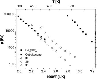
The vapour pressures of 3a–c at different temperatures in comparison to cobaltocene and Co2(CO)8 are depicted in Fig. 1. Irrespective of the substituents, the vapour pressures of 3a–c are lower than the reference system Co2(CO)8 and are in the same order of magnitude as commonly used cobaltocene.41,42 As it is known, the introduction of (CH3)3Si groups into a volatile compound leads to higher vapour pressure and simultaneously a decreased melting point.40 Therefore, it is noteworthy that in this series of molecules the alkyl substitution (3c) leads to an even higher volatility compared to the (CH3)3Si substituted analogues 3a and 3b.
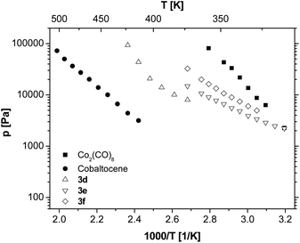
These results prompted us to study the influence of the position of the C,C triple bond within different hexynes on the vapour pressure of the resulting tetrahedranes (3d–f, Fig. 2). The measurements revealed that the alkyl substitution on the C,C triple bond significantly increases the volatility of the dicobaltatetrahedranes up to the range of Co2(CO)8. Furthermore, it can be concluded that the more asymmetric compounds 3e and 3f show higher vapour pressures than the corresponding symmetric molecule 3d.
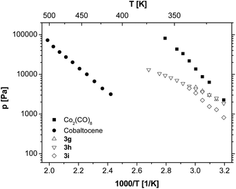
Since 3f exhibits a very high vapour pressure, the influence of the chain length of the appropriate alkyl groups has been investigated by varying the used 1-alkyne from 1-hexyne to 1-nonyne (Fig. 3). The elongation of the alkyl chain of compounds 3f–i leads to a decrease in the resulting vapour pressures. Nevertheless, this effect is much less pronounced than the effect of, for example, varying the position of the C,C triple bond. This behaviour is not unexpected as the compound's asymmetry increases to a minor degree, while the van der Waals interactions and the molar mass of the molecules increase with the chain length.
Thermal behaviour
To determine the behaviour of dicobaltatetrahedranes 3a–i towards temperature, thermogravimetric measurements have been performed and are depicted in Fig. 4. The TG experiments have been carried out at a heating rate of 10 K min−1 and a carrier gas flow (N2) of 60 mL min−1. Please note that the TG traces are highly dependent on the applied heating rate and hence low rates lead to predominant (up to complete) evaporation for all compounds studied. The heating rate was chosen to ensure that not only evaporation is monitored, but also decomposition temperatures can be estimated in order to get a hint for the substrate temperatures in the CVD process. The evaporation behaviour of 3a–i was studied by vapour pressure measurements (see above). | ||
| Fig. 4 TG traces of 3a–c (left), 3d–f (middle) and 3g–i (right); gas flow N2 60 mL min−1, heating rate 10 K min−1. | ||
Among this series of compounds the thermal properties of bis(trimethylsilyl)dicobaltatetrahedrane 3a showed some peculiarities. While for all other compounds 3b–i more than ca. 20 wt% residue was obtained, 3a sublimes predominantly without decomposition (residue: 6 wt%). Hence, the decomposition temperature of 3a might be significantly higher than its sublimation point. Nevertheless, the sublimation as well as in part the decomposition of this compound occurred at temperatures lower than 250 °C as opposed to compounds 3b–i of the series, which show more complex multistep decompositions. This somewhat different behaviour leads to a higher temperature of complete decomposition (3b–i, 350 °C). For 3b to 3g the weight loss exceeds the theoretical value for the formation of elemental cobalt. Hence a significant amount of precursor (up to one third) sublimes without decomposition. Molecules 3h and 3i decompose to residue amounts of 28.2% (3h) and 29.7% (3i), which are in the range of the theoretical cobalt content (3h: 29.75%; 3i: 28.74%).
In summary these results show that molecules 3a–i are sufficiently volatile to be applied in a vaporizer unit of a MOCVD reactor and display low decomposition temperatures below 350 °C. Therefore, dicobaltatetrahedranes 3a–i are promising precursor systems for the efficient formation of thin cobalt layers via metal–organic chemical vapour deposition.
Chemical vapour deposition experiments
Chemical vapour deposition experiments using 3a–i as the cobalt source were carried out with a home-built vertical cold-wall CVD reactor equipped with a continuous evaporation system. The depositions were conducted using nitrogen as the carrier gas (50 mL min−1; 0.25–50 mbar working pressure) on silicon wafers with 100 nm thick thermal SiO2. The substrate temperatures were chosen according to the TG results and are optimized for film formation empirically (Table 2). Preliminary deposition experiments showed that the vaporizer unit can be operated at 25 °C. The deposition was monitored visually to determine the termination moment of the experiment (formation of a metallic layer).| Compd | ϑ precursor [°C] | ϑ deposition [°C] | Gas flow N2 [mL min−1] | Pressure [mbar] | Deposition time [min] | Thickness [nm] | Growth rate [nm min−1] |
|---|---|---|---|---|---|---|---|
| 3a | 25 | 250 | 50 | 0.25 | 30 | 90 | 3.0 |
| 3b 38 | 25 | 350 | 50 | 0.45 | 60 | 70 | 1.2 |
| 3c | 25 | 380 | 50 | 10 | 5 | 35 | 7.0 |
| 3d | 25 | 380 | 50 | 50 | 15 | 50 | 3.3 |
| 3e | 25 | 380 | 50 | 50 | 15 | 60 | 4.0 |
| 3f | 25 | 225 | 50 | 50 | 3 | 70 | 23.3 |
| 3g | 25 | 250 | 50 | 50 | 5 | 50 | 10.0 |
| 3h | 25 | 250 | 50 | 50 | 5 | 50 | 10.0 |
| 3i | 25 | 250 | 50 | 50 | 5 | 50 | 10.0 |
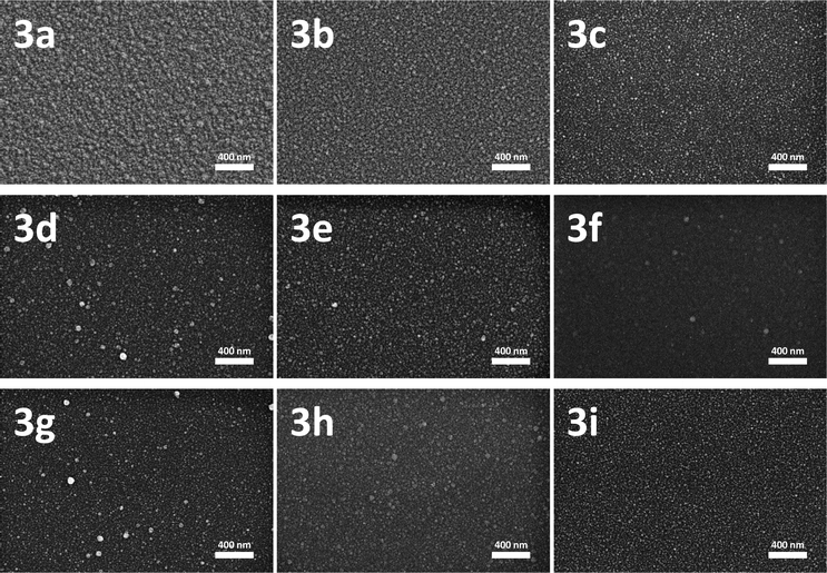
The resulting cobalt layers have been characterized by scanning electron microscopy (SEM). SEM images of the films obtained from 3a–i are depicted in Fig. 5 and demonstrate the homogeneous closed layer formation with a slightly granulated surface for all compounds. The thickness of the layers was determined using SEM images of the cross-section in side view (35–90 nm, Table 2).
Due to the different volatility of 3a–i, the working pressure was adjusted to ensure a film growth within reasonable controllable time (5–60 min). Due to the higher vapour pressure of 3c, when compared with 3a and 3b, the film growth rate is significantly higher despite the fact that a 20 to 40 times higher working pressure was applied. This leads to a decreasing deposition time from 30 min (3a) and 60 min (3b) to 5 min (3c). Since the vapour pressures of 3d–i are even higher than that of 3c the working pressure of the CVD experiments with these precursors was increased to 50 mbar in order to slow down the deposition. Within this series of dicobaltatetrahedranes it becomes clear that the growth rate correlates well with the vapour pressure. The highest growth rate was observed for 3f. It is noteworthy that for 3f–i deposition temperatures as low as 225–250 °C are sufficient for the film formation, while the TG results favour higher temperatures of complete decomposition (above 300 °C, Fig. 4).
The elemental compositions of all deposited films using precursors 3a–i were analysed by energy dispersive X-ray spectroscopy (EDX). Beside the expected signal pattern for cobalt, signals for carbon, silicon and oxygen of significant intensity have been observed. Decreasing the energy of the electron beam from 10 to 3 keV and hence reduction of the penetration depth resulted in a noteworthy decreased intensity of both the silicon and oxygen signals, which is depicted in the example of a layer generated using 3a in Fig. 6. This leads to the conclusion that the SiO2 surface of the silicon substrate was detected. Therefore, for such thin films EDX analysis is an unsuitable methodology for the element composition determination.
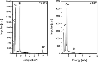 | ||
| Fig. 6 Energy dispersive X-ray spectra of the cobalt layer generated by CVD of 3a at 10 keV (left) and 3 keV (right). | ||
XPS studies enabled the determination of the elemental composition of the deposited films without penetration of the SiO2 layer on the silicon wafer. Concentration quantification was achieved using standard single element sensitivity factors. Since XPS is a surface sensitive measurement method, contaminations on the film surface may be overestimated; therefore, the measurements have additionally been performed after removing a layer of the film by argon ion sputtering (4 keV; 6 min; 2 × 2 mm2 sputtering field). The results are summarized in Table 3.
| Compd | Surface composition [mol%] | Layer compositiona [mol%] | ||||||
|---|---|---|---|---|---|---|---|---|
| C1s | O1s | Si2sb | Co2p | C1s | O1s | Si2sb | Co2p | |
| a After 6 min argon ion sputtering (4 keV). b Si2s was used in the determination since the Si2p overlaps with Co3s. | ||||||||
| 3a | 34.5 | 26.0 | 5.6 | 33.9 | 2.5 | 0.8 | 0.0 | 96.7 |
| 3b 38 | 46.7 | 34.0 | 12.2 | 7.1 | 4.1 | 26.6 | 0.8 | 68.5 |
| 3c | 51.9 | 32.1 | 11.1 | 4.9 | 23.9 | 3.3 | 0.4 | 72.4 |
| 3d | 34.5 | 41.1 | 24.4 | 4.2 | 34.4 | 61.4 | ||
| 3e | 34.6 | 38.8 | 26.6 | 4.4 | 33.2 | 62.4 | ||
| 3f | 47.7 | 40.4 | 11.9 | 13.6 | 25.5 | 60.9 | ||
| 3g | 17.3 | 28.6 | 54.1 | 35.2 | 5.7 | 59.1 | ||
| 3h | 44.5 | 15.3 | 40.2 | 32.3 | 9.3 | 58.4 | ||
| 3i | 44.6 | 14.3 | 41.1 | 36.5 | 6.5 | 57.0 | ||
For all deposited films it was observed that the surface contains noteworthy amounts of carbon and oxygen as well as silicon (3a–3c) impurities, while inside the layer the cobalt content is much higher. For 3a–3c within the layer almost no silicon is found, which leads to the assumption that the (CH3)3Si groups decompose to volatile follow up products and are not involved in the film formation. Hence, for the bis(trimethylsilyl)-substituted dicobaltatetrahedrane 3a, cobalt films with purities as high as 96.7% could be generated. The introduction of alkyl chains to the precursor systems in all cases leads to an increased carbon content of the formed layers. Within the films generated by decomposition of 3d–f relatively high oxygen contents were found, which decrease with the asymmetry of the precursor, whereby the carbon content increases. The cobalt amount is almost constant at ca. 60% for the deposition using alkyl substituted 3d–i. The origin of the oxygen remains unclear. One possible explanation might be a contamination with air during the transfer of the sample between the CVD reactor and the analytical facilities. The deposition of precursors 3g–i leads to cobalt layers containing carbon as the main impurity (up to 36.5%).
Experimental section
General conditions
All reactions were carried out under an atmosphere of argon using standard Schlenk techniques. The solvent was purified by using the MBraun SPS-800.Instrumentation
The 1H NMR spectra were recorded with a BRUKER Avance III 500 spectrometer operating at 500.303 MHz in the Fourier transform mode at 298 K; the 13C{1H} NMR spectra could not be recorded due to the instability of compounds in solutions. Chemical shifts are reported in δ (parts per million) downfield from tetramethylsilane with the solvent as the reference signal (1H NMR: CDCl3, δ = 7.26). Infrared spectra were recorded using a FT Nicolet IR 200 equipment. TG experiments were performed with a METTLER TOLEDO TGA/DSC1 1100 system equipped with an UMX1 balance. CVD experiments were carried out using a home-built vertical cold-wall CVD reactor with a heater dimension of 20 × 20 mm (BACH Resistor Ceramics GmbH). Heating can be adjusted up to 773 K and is controlled by a Gefran 600 module connected with a Pt100 thermo sensor. The carrier gas (N2) was controlled by a MKS type 247 mass flow controller connected to the reactor by heated copper lines. The CVD system was attached to a turbo molecular pump (EXC 120, EDWARDS VACUUM; base pressure: 10−4 mbar). Pressure control of the reactor system was performed by an EDWARDS Active Gauge Controller PKR 251. The surface morphology was investigated by field-emission scanning electron microscopy (SEM) using a ZEISS Supra60 SEM. For some of the samples cross-sectional SEM investigations were carried out to determine the film thickness. Energy-dispersive X-ray analysis using a BRUKER Quantax 400 system attached to the SEM was applied for determining the chemical composition of the films. The sheet resistance was measured with the four-point probe technique using a PROMETRIX Omnimap RS35 station. XPS measurements were carried out using a PREVAC XPS system with a VG Scienta EW 3000 analyser and MX650 X-ray source, producing monochromatic Al Kα radiation.Reagents
Compounds 3a–i were prepared in a modified reaction protocol according to published procedures.35–37 All other chemicals were purchased from commercial suppliers and were used as received.Synthesis
Conclusions
Novel organometallic cobalt(0) MOCVD precursors of type [Co2(CO)6(η2-RC![[triple bond, length as m-dash]](https://www.rsc.org/images/entities/char_e002.gif) CR′)] (R = H, R′ = (CH3)3Si, nC4H9, nC5H11, nC6H13, nC7H15; R = nC3H7, R′ = (CH3)3Si, CH3; R = R′ = C2H5, (CH3)3Si) have been prepared by a straightforward synthetic methodology including the reaction of the appropriate alkynes with Co2(CO)8. The vapour pressure of the cobalt precursors are in the range of cobaltocene and Co2(CO)8. It could be shown that the different substitution at the dicobaltatetrahedranes allows to vary the vapour pressure of these low melting (3a, 70 °C) or liquid (3b–i) compounds. TG analyses demonstrated complete decomposition of the precursors below 350 °C. Hence, molecules 3a–i are suitable for application within a CVD process. The film formation could be realized in a vertical cold-wall CVD reactor under relatively mild conditions, with substrate temperatures down to 225 °C and working pressures of 50 mbar. Film thicknesses of 35–90 nm have been realized which were confirmed by SEM measurements. The elemental composition of the generated reflective films has been analysed using XPS measurements. Cobalt layers of high purity (96.7% Co, 2.5% C, 0.8% O) could be generated by decomposition of the precursor system 3a without the addition of any reactive gas, which is in contrast to [Co2(CO)6(η2-HC
CR′)] (R = H, R′ = (CH3)3Si, nC4H9, nC5H11, nC6H13, nC7H15; R = nC3H7, R′ = (CH3)3Si, CH3; R = R′ = C2H5, (CH3)3Si) have been prepared by a straightforward synthetic methodology including the reaction of the appropriate alkynes with Co2(CO)8. The vapour pressure of the cobalt precursors are in the range of cobaltocene and Co2(CO)8. It could be shown that the different substitution at the dicobaltatetrahedranes allows to vary the vapour pressure of these low melting (3a, 70 °C) or liquid (3b–i) compounds. TG analyses demonstrated complete decomposition of the precursors below 350 °C. Hence, molecules 3a–i are suitable for application within a CVD process. The film formation could be realized in a vertical cold-wall CVD reactor under relatively mild conditions, with substrate temperatures down to 225 °C and working pressures of 50 mbar. Film thicknesses of 35–90 nm have been realized which were confirmed by SEM measurements. The elemental composition of the generated reflective films has been analysed using XPS measurements. Cobalt layers of high purity (96.7% Co, 2.5% C, 0.8% O) could be generated by decomposition of the precursor system 3a without the addition of any reactive gas, which is in contrast to [Co2(CO)6(η2-HC![[triple bond, length as m-dash]](https://www.rsc.org/images/entities/char_e002.gif) C–C(CH3)3)],32 a precursor that required the use of H2 in order to form pure cobalt films. CVD experiments using 3b, 3d and 3e resulted in the formation of reflective metallic layers consisting of a mixture of cobalt and cobalt oxide with minor impurities of carbon, while films generated from 3c and 3g–i consist of cobalt, carbon and minor cobalt oxide impurities. The film formation using 3f as the cobalt source contains a mixture of cobalt, cobalt oxide and carbon.
C–C(CH3)3)],32 a precursor that required the use of H2 in order to form pure cobalt films. CVD experiments using 3b, 3d and 3e resulted in the formation of reflective metallic layers consisting of a mixture of cobalt and cobalt oxide with minor impurities of carbon, while films generated from 3c and 3g–i consist of cobalt, carbon and minor cobalt oxide impurities. The film formation using 3f as the cobalt source contains a mixture of cobalt, cobalt oxide and carbon.
Cobalt compounds discussed in this work are able to generate metallic structures with smooth surfaces and controlled growth rates without the addition of a reactive gas or the application of plasma. Furthermore, the low melting point (for most compounds below 25 °C) associated with the high vapour pressure allows easy processing and handling.
Acknowledgements
We gratefully acknowledge the Bundesministerium für Bildung und Forschung (BMBF) (NANETT, 03IS2011 – “nano system integration network of excellence – application of nano technologies for energy-efficient sensor systems”) and the Fonds der Chemischen Industrie for generous financial support. In addition, we acknowledge Cornelia Kowol for SEM/EDX measurements. We would like to thank Dr André Tuchscherer for help with the CVD reactor. Additionally, we would like to thank Lisa Georgi for many fruitful discussions.Notes and references
- Y.-M. Jeong, J.-K. Lee, S.-C. Ha and S. H. Kim, Thin Solid Films, 2009, 517, 2855 CrossRef CAS PubMed.
- Y. Nakamura, Electrochem. Soc. Trans., 2007, 3, 29 CAS.
- M. F. Chioncel and P. W. Haycock, Chem. Vap. Deposition, 2006, 12, 670 CrossRef CAS.
- N. Li, X. Wang, S. Derrouiche, G. L. Haller and L. D. Pfefferle, ACS Nano, 2010, 4(3), 1759 CrossRef CAS PubMed.
- M. N. Bailich, J. M. Broto, A. Fert, F. Ngugen Van Dau, F. Petroff, P. Etienne, G. Creuzet, A. Friederich and J. Chaselas, Phys. Rev. Lett., 1988, 61, 2472 CrossRef.
- D. Karnaushenko, D. Makarov, C. Yan, R. Streubel and O. G. Schmidt, Adv. Mater., 2012, 24, 4518 CrossRef CAS PubMed.
- J. Q. Xiao, J. S. Jiang and C. L. Chien, Phys. Rev. Lett., 1992, 68, 3749 CrossRef CAS.
- S. S. P. Parkin, R. Bhadra and K. P. Roche, Phys. Rev. Lett., 1991, 66, 2152 CrossRef CAS.
- A. E. Berkowitz, J. R. Mitchell, M. J. Carey, A. P. Young, D. Rao, A. Starr, S. Zhang, F. E. Spada, F. T. Parker, A. Hutten and G. Thomas, J. Appl. Phys., 1993, 73, 5320 CrossRef CAS PubMed.
- T. Maruyama, Jpn. J. Appl. Phys., 1997, 36, L705 CAS.
- T. Maruyama and T. Nakai, Appl. Phys. Lett., 1991, 59, 1433 CrossRef CAS PubMed.
- B. X. Fu and H. Wang, J. Magn. Magn. Mater., 1998, 187, 47 CrossRef.
- M. Hehn, K. Cherifi-Khodjaoui, K. Ounadjela, J. P. Bucher and J. Arabski, J. Magn. Magn. Mater., 1997, 165, 520 CrossRef CAS.
- J. M. Alameda, F. Carmona, F. H. Salas, L. M. Alvarez Prado, R. Morales and G. T. Perez, J. Magn. Magn. Mater., 1996, 154, 249 CrossRef CAS.
- M. E. Gross and K. J. Schnoes, in Chem. Vap. Deposition, Proc. 10th Int. Conf. Electrochem. Soc. Proc., ed. W. Cullen, The Electrochemical Society, Pennington, NJ, 1987, vol. 87–88, p. 759 Search PubMed.
- F. Y. Ogrin and P. W. Haycock, J. Magn. Magn. Mater., 1996, 155, 199 CrossRef CAS.
- M. A. Paranjape, A. U. Mane, A. K. Raychaudhuri, K. Shalini, S. A. Shivashankar and B. R. Chakravarty, Thin Solid Films, 2002, 413, 8 CrossRef CAS.
- G. J. M. Dormans, G. J. B. Meekes and E. G. J. Staring, J. Cryst. Growth, 1991, 114, 364 CrossRef CAS.
- S. W.-K. Choi and R. J. Puddephatt, Chem. Mater., 1997, 9, 1191 CrossRef CAS.
- Y. K. Ko, D. S. Park, B. S. Seo, N. I. Yang, H. J. Yang, H. J. Shin, J. Y. Kim, J. H. Lee, W. H. Lee, P. J. Reucroft and J. G. Lee, Mater. Chem. Phys., 2003, 80, 560 CrossRef CAS.
- J. Lee and J. G. Lee, J. Korean Phys. Soc., 2006, 49, S697 CAS.
- N. Papadopoulos, C.-S. Karayianni, P. Tsakiridis, E. Sarantopoulou and E. Hristoforou, Chem. Vap. Deposition, 2011, 17, 211 CrossRef CAS.
- P. A. Premkumar, A. Turchanin and N. Bahlawane, Chem. Mater., 2007, 19, 6206 CrossRef CAS.
- P. A. Premkumar, N. Bahlawane, G. Reiss and K. Kohse-Hoeinghaus, Chem. Vap. Deposition, 2007, 13, 227 CrossRef CAS.
- Z. Li, D. K. Lee, M. Coulter, L. N. J. Rodriguez and R. G. Gordon, Dalton Trans., 2008, 2592 RSC.
- N. R. M. Crawford, J. S. Knutsen, K.-A. Yang, G. Haugstad, S. McKernan, F. B. McCormick and W. L. Gladfelter, Chem. Vap. Deposition, 1998, 4, 181 CrossRef CAS.
- P. A. Lane, P. E. Oliver, P. J. Wright, C. L. Reeves, A. D. Pitt and B. Cockayne, Chem. Vap. Deposition, 1998, 4, 183 CrossRef CAS.
- A. R. Ivanova, G. Nuesca, X. Chen, C. Goldberg, A. E. Kaloyeros, B. Arkles and J. J. Sullivan, J. Electrochem. Soc., 1999, 146, 2139 CrossRef CAS PubMed.
- N. Deo, M. F. Bain, J. H. Montgomery and H. S. Gamble, J. Mater. Sci.: Mater. Electron., 2005, 16, 387 CrossRef CAS PubMed.
- J. Lee, H. J. Yang, J. H. Lee, J. Y. Kim, W. J. Nam, H. J. Shin, Y. K. Ko, J. G. Lee, E. G. Lee and C. S. Kim, J. Electrochem. Soc., 2006, 153, G539 CrossRef CAS PubMed.
- H. Choi and S. Park, Chem. Mater., 2003, 15, 3121 CrossRef CAS.
- K. Lee, T. Park, J. Lee, J. Kim, J. Kim, N. Kwak, S. Yeom and H. Jeon, Jpn. J. Appl. Phys., 2008, 47, 5396 CrossRef CAS.
- H.-B.-R. Lee and H. Kim, Electrochem. Solid-State Lett., 2006, 9, G323 CrossRef CAS PubMed.
- K. Lee, K. Kim, T. Park, H. Jeon, Y. Lee, J. Kim and S. Yeom, J. Electrochem. Soc., 2007, 154, H899 CrossRef CAS PubMed.
- A. C. Coleman, C. Long, A. Meetsma, B. L. Feringa, W. R. Browne and M. T. Pryce, Dalton Trans., 2009, 7885 RSC.
- H. Lang and U. Lay, J. Organomet. Chem., 1990, 388, C1 CrossRef CAS.
- H. Lang and L. Zsolnai, Z. Naturforsch., A: Phys. Sci., 1990, 45b, 1529 Search PubMed.
- C. Georgi, A. Hildebrandt, A. Tuchscherer, S. Oswald and H. Lang, Z. Anorg. Allg. Chem., 2013, 639, 2532 CrossRef CAS.
- R. A. Friedel, I. Wender, S. L. Shufler and H. W. Sternberg, J. Am. Chem. Soc., 1955, 77, 3951 CrossRef CAS.
- A. Tuchscherer, C. Georgi, N. Roth, D. Schaarschmidt, T. Rüffer, T. Waechtler, S. E. Schulz, S. Oswald, T. Gessner and H. Lang, Eur. J. Inorg. Chem., 2012, 4867 CrossRef CAS.
- M. L. Garner, D. Chandra and K. H. Lau, J. Phase Equilib., 1995, 16, 24 CrossRef CAS.
- L. A. Torres-Gómez, G. Barreiro-Rodríguez and F. Méndez-Ruíz, Thermochim. Acta, 1988, 124, 179 CrossRef.
- P. Paetzold, U. Englert, R. Finger, T. Schmitz, A. Tapper and R. Ziembinski, Z. Anorg. Allg. Chem., 2004, 630, 508 CrossRef CAS.
- K. Asano, Y. Uesugi and J. Yoshida, Org. Lett., 2013, 15, 2398 CrossRef CAS PubMed.
- D. C. Billington, I. M. Helps, P. L. Pauson, W. Thomson and D. Willison, J. Organomet. Chem., 1988, 354, 233 CrossRef CAS.
| This journal is © The Royal Society of Chemistry 2014 |

