Enhancing in vitro bioactivity and in vivo osteogenesis of organic–inorganic nanofibrous biocomposites with novel bioceramics†
Tao
Liu
a,
Xinbo
Ding
a,
Dongzhi
Lai
a,
Yongwei
Chen
a,
Ridong
Zhang
a,
Jianyong
Chen
*a,
Xinxing
Feng
*ab,
Xiaoyi
Chen
c,
Xianyan
Yang
c,
Ruibo
Zhao
d,
Kai
Chen
d and
Xiangdong
Kong
d
aThe Key Laboratory of Advanced Textile Materials and Manufacturing Technology, Zhejiang Sci-Tech University, Hangzhou 310018, China. E-mail: jychen58@163.com; xinxingfeng@hotmail.com; Fax: +86-571-86843169; Tel: +86-571-86843622
bThe Quartermaster Research Institute of the General Logistics Department of the PLA, Beijing 100082, China
cZhejiang-California International Nanosystems Institute, Zhejiang Universtity, Hangzhou 310058, China
dCollege of Life Sciences, Zhejiang Sci-Tech University, Hangzhou 310018, China
First published on 21st July 2014
Abstract
Fabricating bioactive nanofibrous scaffolds from biodegradable polymers to mimic native tissue is an important approach in repairing bony defects. Silk fibroin (SF) may contribute to bone regeneration because of its excellent mechanical properties, slow degradability, and low osteoconductivity. A combination of bioceramic-polymer materials is generally used to provide an improved osteoconductive environment for bone healing. This study attempts developing for the first time an electrospun SF-based biocomposite system by introducing new bioceramics based on mesoporous bioactive glass/hydroxyapatite nanocomposite (MGHA). The addition of MGHA into the SF matrix could regulate the physicochemical properties and surface hydrophilicity, but induce weakened tensile properties as compared to pure SF. The excellent apatite-formation ability of a MGHA-introduced nanocomposite also improved the bioactivity of the composite. The biphasic composite increasingly degraded in PBS or enzyme solution in vitro compared with pure SF. In vivo evaluation of bone formation confirmed that SF/MGHA is more advantageous in bone reconstruction than the SF group for cranial bone defects. These results indicate the suitability of the SF/MGHA composite system in bone defects, demonstrating its potential application in bone tissue regeneration.
1. Introduction
Bone defect treatment is a challenging dilemma for clinicians. Bone grafting materials such as autografts, allografts, metallic screws, and prostheses are applied to reconstruct bones. However, these treatment modalities have well-known drawbacks.1–3 Bioactive porous scaffolds (e.g., natural and synthetic polymers as well as ceramic scaffolds) have been explored and developed as candidates for bone tissue repair and regeneration. In principle, ideal scaffolds as bone grafts should be biodegradable, nontoxic within a specific timescale, and exhibit favorable mechanical properties.4 Organic- and polymer-based scaffolds do not possess the desired compressive modulus.5,6 Alternatively, ceramic scaffolds with low porosity are stiff and fragile, resulting in loosening or fracturing of implants in clinical operations.7 Thus, the development of biomaterials that overcome these limitations has received growing interest. At present, progress in new bone matrix synthesis has fueled interest in producing biocompatible organic–inorganic biphasic scaffolds with appropriate mechanical features.Silk fibroin (SF), a fibrous protein from the silkworm Bombyx mori, has long been used for biomedical suture. Notably, its mechanical flexibility, controllable biodegradability, and biocompatibility make SF a promising biomaterial for both in vitro and in vivo tissue engineering applications.8 These impressive features are related to the SF structure and molecular orientation. For instance, the remarkable mechanical properties of SF originate from the formation of β-sheet secondary structures. The different degrees of β-sheet crystallization induced by different treatments further allow fine control over silk degradation rates.9 Multiple methods also tailor SF into different morphological biomaterials such as films, hydrogels, fiber, sponges, and particles from aqueous processes.8,10–12 Electrospun silk-based nanofibers are relatively simple and well established for the fabrication of micro- and nanoscale scaffolds with controllable pore size and porosity. The engineered electrospun structures display a high surface area for cell attachment and high porosity for improved cell infiltration and nutrient diffusion. More importantly, electrospun mats with fiber diameters between 100 nm and 5 μm, as well as interfiber spacing (i.e., the distance between two adjacent fibers in one plane and often referred to as pore size) within 200 μm, can mimic the topographical context of the native extracellular matrix, thus directing both cell migration, proliferation, and differentiation.4,13,14
A new class of silicate-based bioactive glass called mesoporous bioactive glass (MBG) has recently been proposed as an excellent candidate for bone tissue regeneration and drug carriers. MBG in the ternary SiO2–CaO–P2O5 system possesses high surface area, large pore volume, and a mesoporous structure, all of which result in superior bone-formation bioactivity and degradability compared with non-mesoporous bioactive glass.15–17 Currently, the rapid development of nanotechnology allows advancements in designing a novel MBG/apatite nanocomposite (MGHA). The new MGHA nanocomposite developed by Cicuéndez et al. broadens the MGHA functionality beyond that of its pure state.18 Given its close similarities with bone mineral components, the presence of HA nanocrystals is advantageous in increasing the bioactive and osteoconductive characters of this composite. Our laboratory and other groups have reported that MGHA can be fabricated using carbon spheres and P123 as co-templates.19–21 Recently, Cicuéndez et al. first reported a one-pot process to prepare hierarchical meso–macroporous three-dimensional (3D) MGHA scaffolds by a rapid prototyping technique. In particular, the amine chemical modification of their surfaces significantly improved the biocompatibility of the nanocomposite scaffolds.22 However, to the best of our knowledge, no systematic report exists on such composite scaffolds with a MGHA additive for the formation of a biodegradable polymer.
The present study is designed to incorporate MGHA nanocomposites into SF scaffolds to improve the in vivo bioactivity of polymer-based scaffolds. Based on the preparation of MBHA nanocomposite powders, electrospun SF/MGHA composite scaffolds were first fabricated by adjusting the optimized electrospinning parameters. Physicochemical properties, surface hydrophilicity, mechanical strength, in vitro apatite mineralization, and in vitro degradation behavior of SF/MGHA composite scaffolds were investigated against SF nanofibers. The cranial bone defects model in rats were created to investigate the efficacy of SF/MGHA biocomposites for inducing new bone regeneration. After 4 and 8 weeks post-implantation, the degree of in vivo osteogenesis was evaluated by μCT, histological, and immunohistochemical analyses.
2. Materials and methods
2.1 Materials
B. mori silkworm cocoons were obtained from the Huzhou Academy of Agricultural Science (Huzhou, China). Tetraethyl orthosilicate (TEO, 98%), triethyl phosphate (TEP), calcium nitrate (CaNT), ethanol and other reagents were purchased from Sinopharm Reagents Co., Shanghai and used without further purification. Surfactant pluronic P123 (EO20–PO70–EO20) was purchased from JIDA Co., China.2.2 Preparation of spinning dope
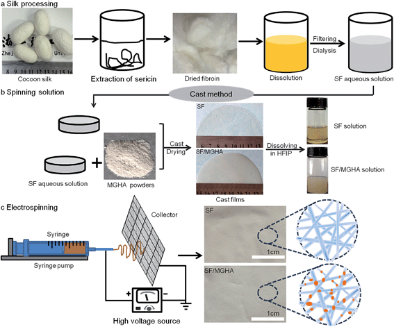
The mesoporous bioactive glass/hydroxyapatite nanocomposite (MGHA) was prepared via hydrothermal synthesis under glucose-assisted conditions as described previously.23 The morphology and microstructure of this nanocomposite are shown in Fig. S1.† As for the organic component, SF was obtained from B. mori cocoons, using the method shown in Fig. 1a. Briefly, B. mori cocoons were degummed twice with 2 wt% neutral soap at 100 °C for 3 h and then washed thoroughly with distilled water to remove sericin and surfactants. After drying, 5 g extracted fibers were dissolved in 50 mL of CaCl2 aqueous/ethanol solution (molar ratio, CaCl2/C2H5OH/H2O = 1/2/8) at 70 °C for 2 h. The fibroin-salt solution was dialyzed against distilled water using cellulose tubular membranes for 3 days to remove the salt. After centrifugation, the final concentration of aqueous silk solution was about 3 wt%, determined by weighing the remaining solid after drying. To prepare spinning dope containing MGHA powders, the MGHA nanoparticles were first added into SF solution to form a uniform mixture (mass ratio, SF/MGHA = 100/5). During the process, appropriate combinations of sonication and magnetic stirring were applied to minimize aggregation. The mixture was transferred into polystyrene dishes and dried in an incubator at 25 °C for 12 h to obtain the blend films, as shown in Fig. 1b. Then, the blend films were dissolved in hexafluoro-2-propanol (HFIP) under stirring to yield spinning SF/MGHA solution with a concentration of 8 wt%. Pure SF spinning solution with the same concentration was also prepared for comparison.2.3 Preparation of SF/MGHA nanofibers
The above viscous spinning solution was transferred into a glass syringe equipped with a stainless steel capillary nozzle. The nozzle was connected to a high-voltage power supply (FC60P2; Glassman High Voltage). In the work the feed rate of the solution (0.5 mL h−1) was precisely controlled by a syringe pump system (KDS 220; KD Scientific), as seen in Fig. 1c. The electrospun SF and SF/MGHA composite scaffolds were treated with 75% (v/v) ethanol/water solution for 30 min to induce β-sheet secondary structures.2.4 Structural and morphological characterization of the electrospun SF and SF/MGHA nanofibers
The molecular weight distributions (MWs) of the SF samples were measured by high performance liquid chromatography (HPLC: Agilent 1100, USA). For sample preparation, the lyophilized SF sponges were dissolved in high purity water and the solution of 0.1% w/v were filtered with a 0.1 μm syringe filter before measurement. The protein concentration was observed by UV absorbance at 215 nm. The MWs of SF were determined through a calibration curve obtained by measuring with standard globular protein kits.24The fiber morphologies of pure SF and SF/MGHA composites were observed using an optical microscope (BX51; Olympus), by field-emission scanning electron microscopy (FESEM: Ultra–55; Carl Zeiss), and transmission electron microscopy (TEM: JEM2100; JEOL). The FESEM images were analyzed with the Image-Pro Plus (IPP) software to acquire the average fiber diameters from 100 fibers random measurements. Pore size distribution of the scaffold was investigated by a capillary flow porometer (Porometer 3Gzh; Quantachrome Instruments). The liquid GQ-16 (GaoQ. Funct. Mater. Int.) was used as the wetting agent for porometry measurements.25 The pore size distribution of electrospun nanofibrous scaffolds was measured with the aid of the computer software coupled to the capillary flow porometer.
The apparent density and porosity characteristics of the electrospun scaffolds were determined using the following equations:
where the bulk density of silk is 1.25 g cm−3 as reported elsewhere.26,27 Swelling properties were tested by immersing the sample in distilled water for 24 h at 37 °C. The swelling ratio of the scaffold and the water content in the scaffolds were calculated as follows:28
| Swelling ratio = (W2 − W1)/W1; |
| Water uptake (%) = [(W2 − W1)/W2] × 100, |
Surface wettabilities of the electrospun scaffolds were characterized by the water contact angle goniometer (DSA100; Krüss Gmbh, Germany). A droplet of 5 μL water was placed on the surface of pure SF and SF/MGHA mats through a stainless steel needle at a rate of 2 μL s−1. Under the ambient condition of constant temperature and humidity (i.e., 35% relative humidity at 27 °C), the water contact angles for three independent mats were achieved and presented as the mean ± SD. The mechanical properties of the samples were characterized using a multi-purpose tensile tester (KES-GI; Kato-Tech, Japan) in tensile mode.29 Firstly, a white paper was cut into a template with width × gauge length, and double-side tapes were glued onto the top and bottom areas of one side. The fiber scaffolds with a planar dimension of 5 mm × 40 mm were then glued onto the top and bottom sides of the paper template along the vertical lines. Each sample was firstly stored under 65% relative humidity at 20 °C for 24 h and then tested at 10 mm min−1 elongation speed for five times. Attenuated total reflectance-Fourier transform infrared spectroscopy (ATR-FTIR) data were gathered with a Nicolet 5700 (Thermo Fisher, USA). The measurements were taken in the range of 4000–600 cm−1 at a resolution of 4 cm−1.
2.5 Bioactivity in vitro
The SBF with ion concentration nearly equal to that of human blood plasma was prepared according to the method proposed by Kokubo and Takadama.30 For in vitro bioactivity, the electrospun SF and SF/MGHA nanofibrous matrices were soaked in SBF at 37.5 °C for 7 days. The SBF was refreshed every other day. At the preset time interval the samples were gently rinsed with DI water several times to remove the soluble inorganic ions completely, and then dried at room temperature for SEM observation and energy dispersive spectrometry (EDS).2.6 Biodegradation in vitro
Biodegradation in vitro was measured by monitoring the weight change of the electrospun mats in enzyme and sodium phosphate buffer (PBS, pH 7.4) solution. Briefly, each sample (70 ± 5 mg, N = 3 per time point) was allowed to incubate in 5 mL solution of 1.0 U per mL Protease XIV (from Streptomyces griseus, EC 3.4.24.31, Sigma) in PBS or in 0.01 M PBS as negative control at 37 °C. At the same time, SF nanofibers were treated in the same manner. The enzyme solution and PBS solution were replaced freshly every 24 h. At designated time points the samples were rinsed in deionized water and prepared for mass balance assessment. The morphologies after degradation or dissolution were also examined using a Carl zeiss FESEM. And the percentage of weight loss of SF scaffolds after different periods of degradation was calculated using the formula:| Water loss (%) = [(W0 − Wt)/W0] × 100, |
2.7 Scaffold transplantation into the calvarial defect of rats
Eighteen male 8 week-old Sprague-Dawley rats (250–300 g) were divided into three groups: (1) blank group; (2) pure SF group; (3) the composite SF/MGHA group. Animal experiments were approved by the committee for animal studies of Zhejiang Sci-Tech University. For establishing the calvarial defect model, all the rats were anesthetized with 10% sodium pentobarbital (4 mg kg−1) and the cranium was exposed through a medial incision. A unilateral round bony defect of 5 mm diameter was created by a dental bur. Each defect in rats flushed with saline to remove bone debris and then implanted with two layers of scaffolds (i.e., pure SF and SF/MGHA with 6 mm diameter). The other rats without filling materials were used as a blank control. After that, the tissues were closed with skin staples layer by layer and these rats were allowed free activity in the cages. The rats were sacrificed by cervical dislocation at 4 and 8 weeks postoperatively.The micro-CT imaging system (μCT-80; Scanco Medical, Switzerland) at an image resolution of 18.0 μm was used to evaluate new bone formation. The three-dimensional (3D) images were reconstructed within the defect region. Meanwhile, the bone volume (BV) was automatically collected and analyzed using the built-in software. After scanning, all the extracted crania were fixed in 4% polyoxymethylene for 48 h and decalcified in 10% EDTA, changed twice weekly for 4 weeks. The specimens were embedded in paraffin blocks. The histological sections (5 μm) were stained with haematoxylin and eosin (H&E), Masson's trichrome (MT), and Alizarin red S (ARS), and then observed using an optical microscope (DM6000b; Leisa). For immunohistochemical assessment, collagen type I (COLI) and osteocalcin (OCN) stainings were also expressed in the de novo bone in the specimens. Under the microscope, IPP software was used to quantify the intensity of immunostaining per specimen. A fixed threshold was applied for positive stain evaluation. And positive pixel areas of new bone formation were divided by total tissue available for growth within the area of interest. The mean optical density (MOD) was reported as relative staining intensities, applying the equation: MOD = (sum IOD)/(sum new bone area).31
2.8 Statistical analyses
The results were expressed as mean ± standard deviation (mean ± SD). Statistical analysis was carried out using one-way ANOVA, and differences of p < 0.05 were considered to be statistically significant.3. Results and discussion
3.1 Morphology of the electrospun scaffolds
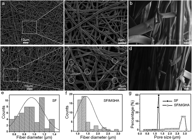
The MWs of regenerated silk solution is a key factor influencing the structure, biodegradability and mechanical properties of SF, which are important in biotechnological applications. Fig. S2.† shows the MWs of regenerated SF prepared under the same dissolution conditions. The SF prepared by dissolving in CaCl2 mixed solvent for 2 h, showed a broad peak at 32 kDa and two other peaks at 6 kDa and 4 kDa. In the present study, the characteristic MWs of SF were used to fabricate the spinning dope during the whole process. An optimized electrospinning technique was employed to prepare pure SF and SF/MGHA non-woven mats. The spinning parameters were identified as follows: 8% concentration, 12 kV voltage, and 12 cm spinning distance. Under fixed spinning conditions, the calculated mean porosity from apparent density measurements of SF/MGHA and SF matrices ranged from 63% to 74% (Table 1). FESEM images (Fig. 2a–d) show the structure, surface, and cross-section morphologies of the obtained electrospun pure SF and SF/MGHA nanofibers. Both SF and SF/MGHA mats presented belt-like morphologies with highly porous and randomly interconnected structures. The surface morphologies of the blend nanofibers appeared to vary with the addition of MGHA (Fig. 2c). Contrary to the smooth morphology of pure SF nanofibers, SF/MGHA nanofibers yielded a rough surface with nanoparticle protuberances. In some segments of the fibers, the MGHA particles were well oriented along fiber axis, and in other segments some particles were exposed on the fiber surface because of the agglomeration of MGHA particles. Belt-like SF fibers in the electrospun mats were also observed in the non-woven mats from the aqueous SF solution (Fig. 2b–d).32 With respect to the belt-like morphology, Koombhongse et al.33 considered that these flattened fibers resulted from the presence of a thin, mechanically distinct polymer skin. In the electrospinning process, atmospheric pressure tended to collapse the tube formed by the skin as the solvent evaporated. Consequently, the circular cross-section became elliptical and gradually flat similar to a ribbon. Therefore, this phenomenon resulted from the rapid evaporation of the solvent on the fiber surfaces, thereby causing the solidification and flatness of the nanofibers on the aluminum foil.| Sample | Apparent density (g cm−3) | Porosity (%) | Pore size (μm) | Swelling ratio | Water uptake (%) |
|---|---|---|---|---|---|
| SF | 0.34 ± 0.06 | 73.5 ± 3.5 | 1.25 ± 0.07 | 1.58 ± 0.12 | 61.3 ± 2.3 |
| SF/MGHA | 0.45 ± 0.08 | 63.8 ± 5.1 | 2.87 ± 0.19 | 1.89 ± 0.09 | 65.4 ± 4.2 |
The fiber diameter distributions of the electrospun pure SF and SF/MGHA fibers are shown in Fig. 2e and f. The fiber diameters for pure SF and SF/MGHA matrices were 0.94 ± 0.23 and 1.39 ± 0.41 μm, respectively. The addition of MGHA particles increased the fiber diameters of the blend fiber, which may be due to conductivity. Solution conductivity is important in determining the fiber diameter and distribution under similar solution concentrations and solvents. In this study, this phenomenon could be explained by the decrease in blend solution conductivity with increasing MGHA content, similar to the decreasing SF content in the matrix. SF is a typical amphiprotic macromolecule electrolyte composed of hydrophobic and hydrophilic blocks.34 Compared with the SF solution, fewer ions were formed in the blend solution when SF/MGHA was affiliated. The conductivity of the composite solution decreased with ion reduction. On the other hand, the decreased charge density caused by the fewer ions also decreased the stretching forces, thus yielding a higher fiber.35 Consequently, pure SF nanofibers had a smaller average fiber diameter than SF/MGHA blend nanofibers.
Electrospun fibrous membranes with micro- and nanoscale porous structures are generally favorable for cellular growth and tissue regeneration. The pore size distributions of pure SF and SF/MGHA mats are shown in Fig. 2g. Along with the incorporation of MGHA powders into the SF scaffolds, the pore diameter increased from 1.25 ± 0.07 μm to 2.87 ± 0.19 μm (Table 1). A similar result was reported by Eichhorn et al.,36 who found that fiber diameter played a dominant role in controlling the scaffold pore diameters, and the increasing fiber diameter also increased the mean pore radius. Thus, SF/MGHA possesses a larger mean pore diameter compared with pure SF because of the increased mean fiber diameter. The internal structure of SF/MGHA composite nanofibers was evaluated by transmission electron microscopy (TEM) as shown in Fig. 3c and d. The TEM image (Fig. 3b) of MGHA powders also show a cluster-like dark zone distributed around the mesopores corresponding to nanocrystalline apatite phase particles. The high-magnification micrograph (inset) of the dark zone shows the lattice spacing at 0.27 nm, corresponding to the (112) HA reflection. This result confirms the presence of HA nanoparticles in the MG nanocomposite. During the fabrication of the blend composite, these MGHA powders were incorporated into the SF polymer. Contrary to the homogeneous internal structure observed in the pure SF nanofiber (Fig. 3a), the MGHA nanoparticles were embedded in the blend fibers (Fig. 3c). However, the nanoparticles in the composite tended to agglomerate and even protrude from the outer surface layers of the composite fibers in some regions (Fig. 3c). Based on a high-magnification image (Fig. 3d), the area presented one-dimensional cylindrical channels from hexagonal structures in the MGHA nanocomposite.
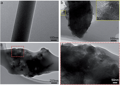 | ||
| Fig. 3 TEM images of (a) pure SF, (b) MGHA nanocomposite, and (c and d) electrospun SF/MGHA nanofibers. | ||
3.2 Swelling, hydrophilic, and mechanical properties
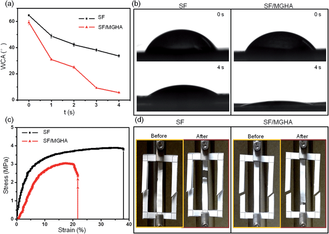
The water-binding ability of scaffolds is important in the evaluation of biomaterial properties for tissue engineering. The related abilities of SF and SF/MGHA mats are listed in Table 1. The swelling ratio and water uptake of the blend SF/MGHA scaffolds were higher than that of pure SF scaffolds, which indicates that the incorporation of MGHA into SF resulted in improved SF bulk hydrophilicity. The surface hydrophilicity of the biomaterials is also important in cell adhesion and growth.37 Thus, the hydrophilicity of the electrospun fiber mats was investigated by measuring the water contact angle (WCA) (Fig. 4a). The initial WCA of the pure SF mat was 64.7° ± 0.3°, which decreased to 33.7° ± 1.0° after 4 s. In contrast, the SF/MGHA mat had an initial WCA of 59.2° ± 1.7° which decreased to 5.6° ± 0.2° after 4 s. The shapes of the water drops for pure SF and SF/MGHA are shown in Fig. 4b. Pure SF nanofibrous mats show hydrophilicity because of their hydrophilic amino groups and carboxylic groups.38 The effect of MGHA on the surface of SF/MGHA scaffolds displayed a decrease in the measured static contact angle, suggesting better hydrophilicity than with pure SF. Hence, the introduction of MGHA into SF could improve the SF hydrophilicity because of the MGHA texture in the composite scaffold. For MGHA particles, the coordinated effects of the mesoporous channels and capillarity within the pores influenced the contact angle of the composite scaffolds.39 Higher hydrophilicity was also observed with the appearance of the micron pore size in the composite structure.40 This phenomenon may have been caused by water penetration through some large pores, and the water was then absorbed by the membrane.The mechanical properties of a biomedical scaffold are important design parameters for maintaining mechanical stability while using the scaffold to fill a damaged area in a host.41 Before strength measurements (Fig. 4d), electrospun fiber mats were cut and glued in tensile mode at a speed of 1 mm s−1 at constant room temperature. The tensile properties of SF and SF/MGHA composite mats were investigated (Fig. 4c). The mats initially indicated a linear increase in stress and then were significantly stretched with increasing strain. A sudden stress drop was also observed with the visible fracture. However, the tensile strength and Young's modulus of the SF/MGHA mat weakened after the MGHA particles were blended. Notably, the brittle characteristic of the SF/MGHA composite mat was expected after glass particles were used in the polymer because of their inherent brittleness. This phenomenon may be related to the particle dispersion in the polymer. Such uniformly distributed HA particles may strengthen the conventional composite and pure PCL.42 Based on the FESEM and TEM images of the SF/MGHA composite, MGHA particles tended to agglomerate in the SF matrix, thereby influencing the mechanical properties of the composite nanofibers. Incorporation of MGHA in this composite system slightly decreased the tensile properties. These observations occurred in tensile strength could be further analysed by detecting the secondary structure of SF.
3.3 Secondary structure of SF and SF/MGHA nanofibers
FTIR is universally applied to monitor the secondary structure of SF. Fig. 5a shows FTIR spectra of pure SF and SF/MGHA nanofibers when treated with ethanol solution. According to Knight's assignment for characteristic bands,43,44 the broad band at 1650 cm−1 (amide I) is assigned to the random coil structure; the bands observed at 1628 and 1698 cm−1 (amide I) correspond to β-sheet and β-turn conformations, respectively. The bands centered at 1540 and 1520 cm−1 (amide II) are classified as the random coil and β-sheet conformations. Besides, the peaks at 1233 and 1264 cm−1 (amide III) are assigned to the random coil and β-sheet conformations. Both of pure SF and SF/MGHA exhibited the characteristic absorption bands from the amide group, indicating that the random coil and β-sheet structures co-existed in the mats. In particular, the incorporation of MGHA into the SF matrix resulted in the appearance of the new bands at 1090 and 1070 cm−1 in FTIR spectra, which were associated with Si–O–Si asymmetric stretching mode and P–O stretching vibration, respectively. Additionally, curve-fitting was done in the amide I region to compare the effect of MGHA on the secondary structure of SF (Fig. 5b and c). The deconvolution results showed that SF/MGHA nanofibers had relatively lower β-sheet content and random coil content than pure SF. Meanwhile, the β-sheet and β-turn contents in the composite mats showed downward trends after adding nanoparticle content into the SF matrix. The change of structural characteristics observed here might induce the low tensile strength when mixing SF with MGHA powders.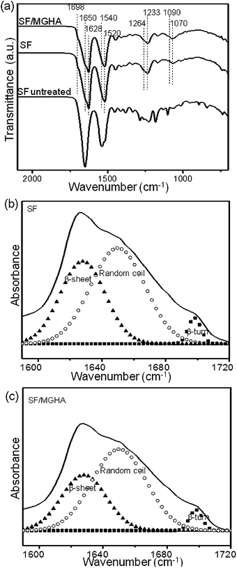 | ||
| Fig. 5 (a) ATR-FTIR spectra of pure SF and SF/MGHA mats compared to the untreated SF mats; curve-fitting results of the FTIR in the amide I region for (b) pure SF and (c) SF/MGHA mats. | ||
3.4 Bioactivity in vitro
Bioactivity is an important concern in the chemical interactions between the implant materials and bone tissue, ultimately affecting the in vivo success of bone grafting materials.30 Changes in the surface morphology of pure SF and SF/MGHA nanofibers upon SBF reaction are shown in Fig. 6. After incubation in SBF for 7 days, a few cauliflower-like HA particles started to appear on the SF nanofiber surfaces. The high-magnification FESEM images show that the crystal lengths approximately ranged from 3 μm to 5 μm (Fig. 4a3). Subsequently, numerous ball-like HA crystals became denser on the SF/MGHA surface, indicating that more apatite particles formed in the composite system. Under high magnification, one part of the composite nanofibers was found to be fully covered by a layer of nanotextured CaP coatings. The increase in phosphorous and calcium content in the EDS analyses (Fig. 6c and d) confirmed the fast deposition of apatite on the surface of nanofiber scaffolds after exposure to SBF. Thus, the CaP nature of all deposits was confirmed by XRD and FTIR (Fig. S3†). Interestingly, the MGHA addition into the composite significantly enhanced its apatite-formation ability in SBF, in contrast to pure SF. Based on the mechanism of apatite formation on silicate bioactive glass,45,46 SF/MGHA scaffolds may have released more Ca and Si ions to the SBF solution than SF scaffolds, whereas the Si content of MGHA was approximately 85%. MGHA with a high surface area in the biocomposites also contributed to the formation of more Si–OH groups on the surface, thus inducing more bone-like mineral deposition on the SF/MGHA surface. More importantly, the lower contact angle facilitated the penetration of the SBF solution into scaffolds, which improved bioactivity. Therefore, tailoring MGHA into the polymer matrix may be an effective method to adjust the apatite-like formation of these biomaterials, enhancing their cell response for optimal application performance.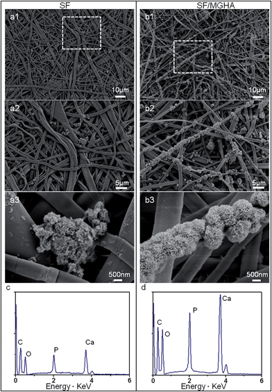 | ||
| Fig. 6 (a1–b3) FESEM images of pure SF and SF/MGHA samples after immersion in SBF for 7 days and (c and d) EDS spectra of the samples immersed in SBF. | ||
3.5 Biodegradation in vitro
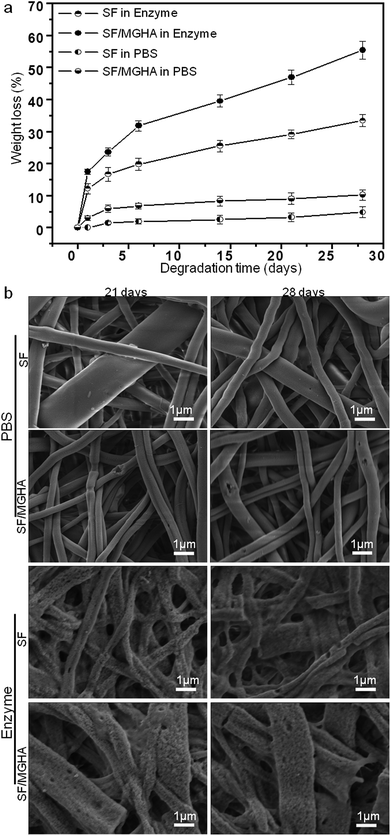
SF and SF/MGHA scaffolds were incubated in protease XIV and PBS (as a control) solutions to evaluate quantitative changes and assess their in vitro degradation behavior. The weight loss percentage of both scaffolds after immersion in protease XIV and PBS solution for various time periods is shown in Fig. 7a. The weight loss of pure SF scaffolds in PBS can be ignored similar to previous phenomena reported by many researchers.47,48 SF scaffolds fabricated by various methods show almost no weight loss in PBS. However, SF mats demonstrated a quicker weight loss in protease XIV than that in PBS solution, indicating that protein-based scaffolds would be susceptible to the enzyme solution and be biodegradable in vivo. Based on these SF in vitro data, a quicker degradation rate may have occurred for SF/MGHA composites in the enzyme solution. The composite biodegradation behavior confirmed this observation. When the MGHA particle was embedded in SF, the composite scaffold degradation rate increased significantly and was higher than that of pure SF scaffolds, whether in protease XIV solution or in PBS solution. The potential reason for this result may be due to the fact that high silicon content in the MGHA system can improve its degradation rate.49 When immersed in the solution, the powder particles were attacked by the surrounding environment, and ions were leached from the particles. Consequently, the particles exposed on the fiber surface were gradually degraded, affecting the weight variation of the composites. In particular, the high surface area and large pore volume of the MGHA powders led to increased water adsorption in MGHA and resulted in faster degradation of the composite scaffolds.Images of the pure SF and SF/MGHA scaffolds incubated in enzyme and PBS solutions are shown in Fig. 7b. During degradation with protease XIV, several cracks and holes appeared on the SF scaffolds after exposure for 21 days, and these features increased with prolonged exposure time. The SF mats gradually became thinner and could not retain their original form after 28 days in the protease XIV solution, indicating more surface erosion with several larger holes. Similar morphological changes were also observed on the surface of SF/MGHA scaffolds. Some fiber fragments were also visible under the action of the protease XIV solution. Comparatively, SF scaffolds incubated in PBS for 21 and 28 days also showed few visible holes from the surface erosion. The formation of some irregular holes on the SF/MGHA surface was probably due to the degradation behavior of these protruded granule-like MGHA particles in PBS. The weight loss was not significantly different, and the structure integrity could be maintained over time during incubation in PBS. Combined with in vitro bioactivity, the results obtained for SF/MGHA clearly represent the appropriate MGHA additive in the silk-based scaffolds, which mainly altered the material bioactivity and degradation kinetics favorable for bone repair and regeneration.
3.6 In vivo bone formation in the calvarial defect model
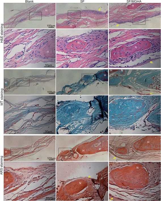
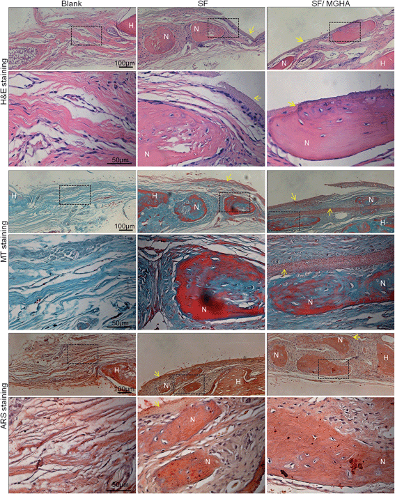
A rat critical bone defect model, with 5 mm diameter was established as the critical size of the nonhealing defect (Fig. 8a), to further evaluate the bone regeneration ability and in vivo osteogenesis of the prepared scaffolds. Pure SF and SF/MGHA scaffolds were implanted into punched rat calvarial and then recovered at the designated time after the operation. In particular, the untreated control without filling scaffolds served as the blank group. Notably, none of the animals died during the in vivo experiments, and no inflammation at the surgical interface sites was observed. Digital images of the cranial bones separated from rats are shown in Fig. 8b. The defect zone in the blank control was intact after 4 weeks to 8 weeks. Similarly, the implanted scaffolds were exposed on the defect. Using 3D-μCT reconstruction, the blank group revealed only fibrous tissues around the border. A significant increase in calcified tissues in the defects filled with SF and SF/MGHA scaffolds was observed. The μCT results (Fig. 8c) showed that the SF/MGHA biocomposite scaffold in which MGHA was loaded into the SF matrix was most effective at promoting mineralization within the defect, indicating better bone repair ability than the blank and pure SF scaffolds. Quantitative analysis from the μCT data shows that bone volume increased with time at the cranial bone defect model. The bone volume in the SF/MGHA composite was significantly higher than those in the blank and SF groups (p < 0.05; Fig. 8d). The μCT results revealed that remarkable bone formation and defect regeneration in the bone defect, in which the SF/MGHA composite had been implanted, was found as further confirmed by the histological analysis.Histological examination of specimens from the blank group at 4 and 8 weeks post-surgery reveals a lack of bone-like tissue. The blank group covered with fibrous tissue showed no signs of new bone formation 4 and 8 weeks post-implantation (Fig. 9 and 10). Standard hematoxylin and eosin (H&E) staining reveals that SF/MGHA scaffolds had better in vivo bone formation ability than pure SF scaffolds at 4 and 8 weeks. At 4 weeks after implantation, larger bones were found in the area grafted with SF/MGHA in contrast to the small bones in the pure SF group. Particularly, newly formed bone island containing osteocytes was directly adjacent to the scaffolds for both implants. The new bone observed at the implant–host tissue interfaces was due to effects mediated by invading murine cells from the surrounding host tissue at the defect site.50 Both scaffolds showed more new bone material with prolonged implantation periods. At 8 weeks post-implantation, more new bone material formed in the defects filled with SF/MGHA scaffolds compared with pure SF scaffolds. The new bone island started from the ends of the host bone to the central part of the SF/MGHA implants. In particular, both scaffolds had been degraded slowly and were still detectable. Masson's trichrome (MT) staining was also used to identify the bone healing effect in calvarial defects. At 4 weeks, the newly formed collagen tissues were stained blue in the SF group. However, both newly formed blue-stained collagen tissues and some mature red-stained collagen fibers at the margin of the bone defect were observed in the SF/MGHA group. At 8 weeks, the red-stained mineralized bone matrix was observed in the SF and SF/MGHA groups. The new bone formation area in the SF/MGHA group was higher than that in the pure SF group. Alizarin Red S (ARS) staining results also showed that the SF/MGHA group induced more calcium deposition in tissue sections than the pure SF group, but no calcification was observed in the blank group (Fig. 9 and 10).
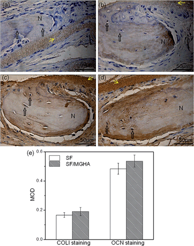
Immunohistochemical analysis was performed to detect the expression of bone matrix proteins. Positive type I collagen (COLI) and osteocalcin (OCN) staining on the new bone tissues in both SF/MGHA and SF scaffolds implanted for 8 weeks are shown in Fig. 11. COLI expressed in the SF/MGHA group (Fig. 11b) was clearly stronger than that in the SF group (Fig. 11a). The healing defects grafted with SF/MGHA (Fig. 11c) exhibited a higher expression level of OCN than those in the SF group (Fig. 11d), and typical osteocytes were found in the new bone matrix. The quantitative analysis from the MOD data is shown in Fig. 11e. For both COL1 and OCN immunostaining, MOD values of the SF/MGHA group were higher than those of the SF group, indicating a strong intensity of COL1 and OCN immunoreactivity in the bone matrix of the SF/MGHA composite group. Thus, the novel SF/MGHA scaffolds yielded an increased osteoconductive environment to augment bone regeneration compared with the SF scaffolds.
The good bone regeneration ability of the SF/MGHA scaffolds could be attributed to the chemical interactions between the graft material and native host tissue as well as their surface bioactivity. Bioactivity has been proven as the bone-bonding ability of bioactive materials to facilitate osteogenesis in vivo, as reported by 45S5 glass, A–W glass ceramics, and CaSiO3 ceramics.30,51,52 Wu et al. prepared MBG/silk scaffolds by a freeze-drying method and further implanted them into calvarial defects in adult severe combined immunodeficient mice.53 They found that MBG/silk scaffolds with improved bioactivity were superior to BG/silk scaffolds in inducing new bone formation. Considering material composition, the presence of MGHA particles is important in assisting the regeneration of bone defects. For MGHA nanocomposites, Cicuéndez et al. demonstrated that MGHA exhibited fast apatite-mineralization ability in SBF. This MGHA nanocomposite also improved the adhesion and proliferation of fibroblast and osteoblast cells compared with MBG.18 We also show in our study that MGHA improved the in vitro mineralization compared with MBG. This study illustrates that SF/MGHA enhanced bioactivity to facilitate bone growth in vivo according to histological examination and immunohistochemical analysis. An appropriate biodegradation rate of implants was conducive to form a porous network that would support the attachment and proliferation of osteoblast cells as well as new bone formation. For SF/MGHA scaffolds, the in vitro biodegradation study confirmed that MGHA particles with larger surface areas facilitated silica biodegradation in vitro through particle dissolution, leading to morphological changes on the surface. The appearance of holes after prolonged treatment may provide space and environment for matrix deposition and tissue growth. The faster release of silicon ions from the composite scaffolds modified the healing microenvironment and activated osteoblast in-growth and gene expression around the defects as reported in the literature.54,55 Accordingly, SF/MGHA scaffolds showed remarkable bone formation and bone regeneration in bone defects, demonstrating the potential of these nanocomposite materials for bone defect treatment.
4. Conclusion
Nanofibrous SF/MGHA scaffolds with high porosity and large pore size were prepared by incorporating MGHA nanocomposite powders into silk scaffolds for the first time. In the case of organic–inorganic biocomposites, their physicochemical properties such as pore size, swelling properties, and surface hydrophilicity were improved by introducing the MGHA nanocomposite, whereas a decrease in tensile properties was observed. The appropriate MGHA additive also modified the material bioactivity, degradation kinetics, and morphological changes of the matrix materials. After implantation into calvarial defects, SF/MGHA composite scaffolds with enhanced bioactivity provided a favorable microenvironment for the in-growth of osteoblast cells to heal the defect. These observations collectively suggest that incorporating MGHA into SF scaffolds is an effective method to construct tissue scaffolds in bone defect repair.Acknowledgements
The authors thank Dr J. Wang and Dr L. Lin for assistance with animal studies. This study is supported by the National Natural Science Foundation of China (51273181, 51102211, 81301326), Zhejiang Provincial Natural Science Foundation of China (LY14E030014), and the Outstanding Postgraduate Dissertation Growth Foundation of Zhejiang Sci-Tech University (2013YBPY05).Notes and references
- R. Dimitriou, E. Jones, D. McGonagle and P. V. Giannoudis, BMC Med., 2011, 9, 66 CrossRef PubMed.
- D. W. Hutmacher, Biomaterials, 2000, 21, 2529–2543 CrossRef CAS.
- M. M. Stevens, Mater. Today, 2008, 11, 18–25 CrossRef CAS.
- P. A. Gunatillake and R. Adhikari, Eur. Cells Mater., 2003, 5, 1–16 CAS.
- I. Martin, V. P. Shastri, R. F. Padera, J. Yang, A. J. Mackay and R. Langer, et al. , J. Biomed. Mater. Res., 2001, 55, 229–235 CrossRef CAS.
- P. D. Waite, R. B. Morawetz, H. E. Zeiger and J. L. Pincock, Neurosurgery, 1989, 25, 214–217 CrossRef CAS PubMed.
- H. J. Kim, U. J. Kim, G. Vunjak-Novakovic, B. H. Min and D. L. Kaplan, Biomaterials, 2005, 26, 4442–4452 CrossRef CAS PubMed.
- C. Vepari and D. L. Kaplan, Prog. Polym. Sci., 2007, 32, 991–1007 CrossRef CAS PubMed.
- H. Jin, J. Park, V. Karageorgiou, U. Kim, R. Valluzzi and P. Cebe, et al. , Adv. Funct. Mater., 2005, 15, 1241–1247 CrossRef CAS PubMed.
- Y. Tamada, Biomacromolecules, 2005, 6, 3100–3106 CrossRef CAS PubMed.
- L. Liu, X. G. Yang, H. Y. Yu, C. Ma and J. M. Yao, RSC Adv., 2014, 4, 14304–14313 RSC.
- L. Zhou, Q. Wang, J. Wen, X. Chen and Z. Z. Shao, Polymer, 2013, 54, 5035–5042 CrossRef CAS PubMed.
- M. Simonet, N. Stingelin, J. G. F. Wismans, C. W. J. Oomens and F. P. T. Baaijens, J. Mater. Chem. B, 2014, 2, 305–313 RSC.
- H. Lee, C. H. Jang and G. H. Kim, J. Mater. Chem. B, 2014, 2, 2703–2713 RSC.
- X. X. Yan, C. Z. Yu and D. Y. Zhao, et al. , Angew. Chem., Int. Ed., 2004, 43, 5980–5984 CrossRef CAS PubMed.
- C. Wu, W. Fan and J. Chang, J. Mater. Chem. B, 2013, 1, 2710–2718 RSC.
- W. Xia and J. Chang, J. Controlled Release, 2006, 110, 522–530 CrossRef CAS PubMed.
- M. Cicuéndez, M. T. Portolés, I. Izquierdo-Barba and M. Vallet-Regí, Chem. Mater., 2012, 24, 1100–1106 CrossRef.
- T. Liu, D. Lai, X. Feng, H. Zhu and J. Y. Chen, Ceram. Int., 2013, 39, 3947–3956 CrossRef CAS PubMed.
- T. Liu, X. B. Ding, X. Yang, Z. Gou, J. Chen and X. X. Feng, J. Non-Cryst. Solids, 2014, 389, 104–112 CrossRef CAS PubMed.
- D. Jagadeesan, C. Deepak, K. Siva and M. Eswara-Moorthy, J. Phys. Chem. C, 2008, 112, 7379–7384 CAS.
- M. Cicuéndez, M. Malmsten, J. Doadrio, M. T. Portolés, I. Izquierdo-Barba and M. Vallet-Regí, J. Mater. Chem. B, 2014, 2, 49–58 RSC.
- T. Liu, D. Lai, X. Feng, H. Zhu and J. Chen, Mater. Lett., 2013, 92, 444–447 CrossRef CAS PubMed.
- H. Cho, C. Ki, H. Oh, K. Lee and I. Um, Int. J. Biol. Macromol., 2012, 51, 336–341 CrossRef CAS PubMed.
- K. Zhang, H. Wang, C. Huang, X. Mo and Y. Ikada, J. Biomed. Mater. Res., Part A, 2010, 93, 984–993 Search PubMed.
- V. Thomas, D. R. Dean, M. V. Jose, B. Mathew and Y. K. Vohra, Biomacromolecules, 2007, 8, 631–637 CrossRef CAS PubMed.
- J. Ayutsede, M. Gandhi, S. Sukigara, M. Micklus, H. Chen and F. Ko, Polymer, 2005, 46, 1625–1634 CrossRef CAS PubMed.
- Q. Lu, X. Zhang, X. Hu and D. L. Kaplan, Macromol. Biosci., 2010, 10, 289–298 CrossRef CAS PubMed.
- Z. M. Huang, Y. Z. Zhang, S. Ramakrishna and C. T. Lim, Polymer, 2004, 45, 5361–5368 CrossRef CAS PubMed.
- T. Kokubo and H. Takadama, Biomaterials, 2006, 27, 2907–2915 CrossRef CAS PubMed.
- J. R. Grandis, M. F. Melhem, E. L. Barnes and D. J. Tweardy, Cancer, 1996, 78, 1284–1292 CrossRef CAS.
- J. He, Y. Qin, S. Cui, Y. Gao and S. Wang, J. Mater. Sci., 2011, 46, 2938–2946 CrossRef CAS.
- S. Koombhongse, W. X. Liu and D. H. Reneker, J. Polym. Sci., Part B: Polym. Phys., 2001, 39, 2598–2606 CrossRef CAS PubMed.
- K. Zhang, H. Wang, C. Huang, Y. Su and X. Mo, J. Biomed. Mater. Res., Part A, 2010, 93, 984–993 Search PubMed.
- T. Sill and H. A. Recum, Biomaterials, 2008, 29, 1989–2006 CrossRef CAS PubMed.
- S. J. Eichhorn and W. W. Sampson, J. R. Soc., Interface, 2005, 2, 309–318 CrossRef PubMed.
- Z. Ma, C. Gao, Y. Gong and J. Shen, Biomaterials, 2005, 26, 1253–1259 CrossRef CAS PubMed.
- L. Li, H. Li, Y. Qian, S. Li, G. K. Singh, L. Zhong, W. Liu, Y. Lv, K. Cai and L. Yang, Int. J. Biol. Macromol., 2011, 49, 223–232 CrossRef CAS PubMed.
- X. Li, J. Shi, X. Dong, L. Zhang and H. Zeng, J. Biomed. Mater. Res., Part A, 2008, 84, 84–91 Search PubMed.
- N. A. Ochoa, M. Masuelli and J. Marchese, J. Membr. Sci., 2003, 223, 201–211 CrossRef.
- D. E. Discher, P. Janmey and Y. Wang, Science, 2005, 310, 1139–1143 CrossRef CAS PubMed.
- H. Kim, J. Biomed. Mater. Res., Part A, 2007, 83, 169–177 CrossRef PubMed.
- S. Ling, Z. Qi, D. P. Knight, Z. Shao and X. Chen, Biomacromolecules, 2011, 12, 3344–3349 CrossRef CAS PubMed.
- X. Chen, D. P. Knight and Z. Shao, Soft Matter, 2009, 5, 2777–2781 RSC.
- L. Hench and J. Wilson, Science, 1984, 226, 630–636 CAS.
- C. Wu, Y. Ramaswamy, Y. Zhu, R. Zheng, R. Appleyard and H. Zreiqat, Biomaterials, 2009, 30, 2199–2208 CrossRef CAS PubMed.
- R. Horan, K. Antle, A. Collette, Y. Huang and J. Moreau, et al. , Biomaterials, 2005, 26, 3384–3393 CrossRef PubMed.
- J. Zhou, C. Cao, X. Ma, L. Hu, L. Chen and C. Wang, Polym. Degrad. Stab., 2010, 95, 1679–1685 CrossRef CAS PubMed.
- X. Yang, L. Zhang, X. Chen, X. Sun and Z. Gou, et al. , J. Non-Cryst. Solids, 2012, 358, 1171–1179 CrossRef CAS PubMed.
- L. Meinel, R. Fajardo, S. Hofmann, R. Langer, J. Chen, B. Snyder, G. Vunjak-Novakovic and D. Kaplan, Bone, 2005, 37, 688–698 CrossRef CAS PubMed.
- L. L. Hench, Biomaterials, 1998, 19, 1419–1423 CrossRef CAS.
- S. Xu, K. Lin, Z. Wang, J. Chang, L. Wang, J. Lu and C. Ning, Biomaterials, 2008, 29, 2588–2596 CrossRef CAS PubMed.
- C. T. Wu, Y. F. Zhang, Y. H. Zhou, W. Fan and Y. Xiao, Acta Biomater., 2011, 7, 2229–2236 CrossRef CAS PubMed.
- K. J. Burg, S. Porter and J. F. Kellam, Biomaterials, 2000, 21, 2347–2359 CrossRef CAS.
- I. D. Xynos, M. V. Hukkanen, J. J. Batten, L. D. Buttery, L. L. Hench and J. M. Polak, Calcif. Tissue Int., 2000, 67, 321–329 CrossRef CAS PubMed.
Footnote |
| † Electronic supplementary information (ESI) available: FESEM image of a MGHA nanocomposite, small-angle and wide angle XRD patterns of the MGHA nanocomposite, the characteristic MW distribution of regenerated SF by dissolution in CaCl2/H2O/EtOH, wide-angle patterns and ATR-FTIR spectra of pure SF and SF/MGHA mats before and after soaking in SBF, MG-63 cells morphology on pure SF and SF/MGHA nanofibrous membranes for 2 days, the MTT assay and ALP activity for MG-63 cultured on the pure SF and SF/MGHA composite scaffolds. See the appendix file. See DOI: 10.1039/c4tb00889h |
| This journal is © The Royal Society of Chemistry 2014 |

