 Open Access Article
Creative Commons Attribution 3.0 Unported Licence
Morphological control of calcium phosphate nanostructures using lyotropic liquid crystals†
Wenxiao
He
,
Yu
Fu
and
Martin
Andersson
*
Department of Chemical and Biological Engineering, Chalmers University of Technology, Göteborg SE-41296, Sweden. E-mail: martin.andersson@chalmers.se
First published on 20th March 2014
Abstract
Organisms use “soft” organic compartments to control the morphology of the embedded “hard” minerals. Here we present a simple method using liquid crystal (LC) phases as “soft” and “inert” templates to prepare nanostructured calcium phosphates (CaPs), which are inorganics of known bioefficacy. Specifically, 6 nm-thick CaP nanowires and CaP sheets that precisely replicate reverse hexagonal (H2) and lamellar (Lα) LCs have been successfully synthesized and we attribute this to the sufficient spatial regulation offered by the negative (H2) or flat curvature (Lα) of the aqueous domain. A normal hexagonal (H1) phase possesses a positive curvature of the aqueous domain, therefore limited spatial restriction. For this reason, precise replication of the H1 phase by CaP has not been possible. Interestingly, the dynamic nature of the template allowed the construction of micron-sized brushite objects with a laminated structure decorating a specific facet, possibly as a result of epitaxial overgrowth of nano-sized brushite subunits.
1. Introduction
Skeletal biominerals possess distinctive morphological, compositional, crystallographic features and organizational order, and thereby exhibit superior material properties. An eminent example is the mineral phase in mammalian bone. Bone apatite nanoplatelets (a highly substituted polymorph of calcium phosphate, CaP) uniaxially align within the collagen matrix, which provide mammals optimal protection, support and other specialized functions.1 The synthesis of these biominerals mostly proceeds within micro- to nano-scopic compartments, i.e. structural matrix assembled by insoluble biomacromolecules.1–4 In addition to the spatial confinement, soluble components including ions and nonstructural biomacromolecules synergistically modulate the mineralization process.1–4 To elucidate the geometric effects in tuning the morphology and polymorphism of biominerals, herein, we report the “softly” confined morphogenesis of CaPs into well-aligned nanowires, nanosheets, ordered laminated structures in “inert” liquid crystal (LC) phases, as well as a site-specific-decoration strategy to construct CaP superstructures with ordered nano-features. The precise control of CaP nanostructures by gentle spatial confinement and the possibility to add-on the structure onto pre-existing architectures offers new opportunities for rational design of nano-inorganics and hybrid materials for advanced applications including artificial bone, biocompatible sensing and nanophotonic devices.With compositions close to the bone mineral and widely recognized bioefficacy, CaP has been the predominant mineral family utilized in biomedical research and industry, where researchers have endeavored to obtain CaP materials with well-defined structures.5,6 Amorphous calcium phosphate (ACP), dicalcium phosphate (dihydrate: DCPD, brushite; anhydrous: DCPA, monetite), octacalcium phosphate (OCP), and calcium deficient hydroxyapatite (CDHA) are the CaP phases that can be formed under near-physiological conditions (in the pH range of 6–8 at room temperature and air pressure) and therefore retain biological relevance.5,7–10 The anisotropic crystal growth of CaP polymorphs is counterproductive to morphological control.11 Moreover, the competition between CaP phases during precipitation further introduces complexity for controlled morphogenesis. Strategies including utilizing active additive/template–CaP interaction, biological templates and hard templates have been adopted to actively and/or geometrically regulate CaP growth.12–17 However, these approaches have several limitations: as in the case of using active additive/templates, specially designed macromolecules that could direct CaP nucleation and crystallization are needed; while in the case of biological templates, an additional precursor infiltration step as well as matrices from restricted sources like demineralized biological samples are required; whereas for hard templates, the structural rigorousity of the templates cannot truly reflect “soft” biological confinements and superstructures cannot be developed from them. On the other hand, synthetic hydrogels with structural flexibility have long been used as scaffolds for biomimetic mineralization, yet, the lack of an ordered nanostructure in most systems does not allow precise control over CaP morphologies. LC phases possessing well-organized nanometric aqueous domains are ideal matrices for biomimetic mineralization, as in natural bone the collagen matrix is itself essentially a LC. Yet there are few reports on the successful replication of CaP from LC phases, as forces holding the LC structure (hydrophobic interaction between self-assembled amphiphilic polymers) can be too weak to restrain anisotropic growth of crystalline CaPs.18 To overcome this, our previous strategy was to biomimetically employ an amorphous intermediate phase. Specifically, reverse hexagonal (H2) LC was used to synthesize uniform ACP nanospheres, from which apatite nanoparticles with well-defined morphology and bone-resembling features were prepared through controlled crystallization.19
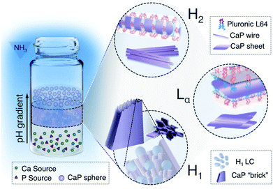
The current study focuses on the manipulation of CaP morphogenesis and polymorphism in confined nanospace provided by H2, lamellar (Lα) and normal hexagonal (H1) LCs. We show that a commercially available nonionic block-copolymer can be used to construct matrices with varied degree of spatial confinement, so that it can guide CaP growth into ACP, monetite (DCPA) or brushite (DCPD) with morphologies replicating the matrix (Fig. 1). The choice of nonionic block-copolymer assemblies may on one hand purely provide spatial restriction during mineralization without active polymer–crystal interaction, thus the technique and outcome can be translated to other compartmentalized matrices; on the other hand, it may also allow re-arrangement of the template structure during particle growth. The flexibility of this system enables us to produce brushite crystals with hierarchical structures (Fig. 1, H1).
2. Experimental
2.1 LC gel preparation
All chemicals were of analytical grade, purchased from Sigma-Aldrich (except Pluronic F127, which was kindly donated by BASF) and used without further purification. Pluronic L64 (EO13PO30EO13) and F127 (EO100PO70EO100) were utilized to form different LC phases. Ca(NO3)2·4H2O (0.84 M) and H3PO4 with a Ca/P molar ratio of 1.67 were dissolved in Milli-Q water. To form a LC gel with the desired structure, pre-mixed precursor solution, Pluronics and oil were mixed evenly according to the recipes listed in Table 1.20,21 Gel samples with a thickness of ca. 1 mm, 2.5 mm or 35–40 mm were prepared by filling glass vials (20 mL, 57.00 × 27.50 mm, VWR) with ca. 0.4 g, 1 g or 15 g of the as-formed liquid crystalline (LC) gel having the desired structure. In one of the glass vials, pH paper (pH range: 1–11 or 1–14) was cut into small pieces and mixed with the LC gel, which was later on used as a pH indicator for the reaction (as shown in Fig. S1c, ESI†).2.2 Reaction in ammonia atmosphere
After preparation, the glass vials were tightly sealed and stored for 24 h to reach equilibrium. An additional sonication step (sonication bath, 60 min) was applied to the Pluronic F127-based H1 gel sample. After that, the gels were placed in the desiccator cabinet (7 × 12 × 12 inch) with an ammonia atmosphere, as illustrated in the ESI Fig. S1a,† where the beaker in the lower part contained varied concentrations and volumes of ammonium hydroxide solution. By diffusion of ammonia gas into the LC gel, CaP precipitated from the aqueous domain of the LC phase. After 24–72 h, the glass vials were taken out from the desiccator cabinet and gel samples were collected accordingly to their depth from upper gel surface (Fig. S1c, ESI†) or pH ranges (pH value of gel layers at certain depths was read from the pH indicator, as shown in Fig. S1c†). The collected gel samples were dispersed in ethanol and centrifuged (Hettich ALC) for 10 min (1585 × g, 2500 rpm). Then the supernatant was removed gently and the sedimentation was re-dispersed in ethanol. This purification process was repeated at least 3 times.2.3 Characterization
Transmission electron microscopy (TEM) analysis was performed on a JEOL 1200EX II microscope operating at 120 kV. The TEM specimens were prepared on a lacey carbon coated copper grid by evaporating a drop of CaP suspension in ethanol. Scanning electron microscopy (SEM) was also performed on the TEM sample grid (by sticking onto SEM stub using carbon tape), using a LEO ULTRA 55 FEG at an accelerating voltage of 2 or 5 kV. X-ray powder diffraction (XRD) patterns were recorded using a Bruker D8 Advance X-ray diffractometer with Cu-Kα1 radiation (λ = 1.54056 Å). All the crystalline phases were identified and semi-quantitatively analysed based on reference intensity ratio (RIR) values using the Search/Match module of DIFFRAC EVA (Bruker AXS) and ICDD database. Small Angle X-ray Scattering (SAXS) experiments were performed on the prepared LC gels before and after the synthesis using synchrotron radiation. The experiments were performed at the I911 beamline at MAX-lab (Lund, Sweden). The wavelength was 0.91 Å and a two-dimensional MarCCD 165 mm detector was used. Samples were sealed in a slit (1 mm thick) enclosed by two parallel transparent cellophane films within a stainless steel sample holder mounted in an evacuated sample chamber. The data were collected for 60–180 s and the used q-range (q = 4π![[thin space (1/6-em)]](https://www.rsc.org/images/entities/char_2009.gif) sin
sin![[thin space (1/6-em)]](https://www.rsc.org/images/entities/char_2009.gif) θ/λ) was 0.1–4.0 nm−1.
θ/λ) was 0.1–4.0 nm−1.
3. Results and discussion
TEM studies of CaP particles grown from a Pluronic L64-based H2 LC gel presented varied morphologies depending on the sampling time point and position. CaP nanospheres with a diameter of roughly 11 nm formed exclusively in the upper 3 mm-thick gel layer (Fig. 2a) after 48 h of reaction. The corresponding selected area electron diffraction (SAED) pattern (Fig. 2b) shows that they are ACP, which agrees with our earlier observation with half the precursor concentration.19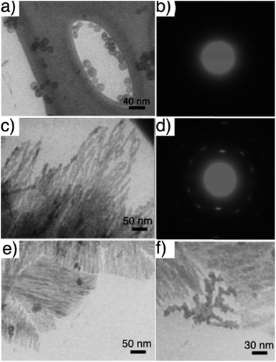 | ||
| Fig. 2 TEM images of CaP particles obtained from H2 LC gel when collected from (a) upper 3 mm-thick gel after 48 h and (b) the corresponding SAED pattern, (c) gel layer 3–6 mm below the surface after 72 h and (d) the corresponding SAED pattern, (e) and (f) same condition as (c) but with a gel equilibration time of 10 h instead of 24 h. Gel recipe: L-1 in Table 1. Gel thickness: 35–40 mm. Ammonia dose: 300 mL 35 wt% NH3OH solution. | ||
In the gel layer 3–6 mm below the surface, CaP particles with unsettled morphologies (Fig. S2a, ESI†) were harvested after 24 h of reaction, indicating an early structural development. Whereas after 48 h of reaction, CaP nanowires with a diameter of ca. 6 nm (Fig. S2b, ESI†) were formed, together with ACP nanospheres. With a prolonged reaction time of 72 h, the nanowire shape of CaPs (Fig. 2c) retained in the same sampling position. The electron diffraction pattern of these nanowire arrays (Fig. 2d) unveils the crystallinity of the sample. The arc-like diffraction spots indicate the presence of crystallographic orientation within the nanowire arrays. However, it has been difficult to resolve the CaP phase by XRD analysis (Fig. 3a), in which the diffuse pattern implies relative low abundance and poor crystallinity of the nanowires. Yet the star-marked region in the diffractogram might suggest a monetite phase of the nanowires. These nanowire arrays seem to align in the gel as observed under optical microscopy (Fig. S3, ESI†), in which each hair-like feature represents an assembly of CaP nanowires.
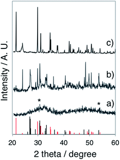 | ||
| Fig. 3 XRD pattern of (a) the CaP nanowires obtained from the gel layer 3–6 mm below the surface of a 35–40 mm thick H2 LC gel after 72 h of reaction (gel recipe: Table 1 L-1, ammonia dose: 300 mL 35 wt% NH3OH solution), (b) the CaP sheets obtained from the gel layer with pH 9 of a 35–40 mm thick Lα sample after 24 h of reaction (gel recipe: Table 1 L-3, ammonia dose: 80 mL 35 wt% NH3OH solution), and (c) the CaP bricks obtained from the gel layer 12–15 mm below the surface (pH 9–10) of a 35–40 mm thick H1 LC after 48 h of reaction (gel recipe: Table 1 F-1, ammonia dose: 80 mL 35 wt% NH3OH solution.). Bottom: the standard monetite (black) and brushite (red) data. Diffractograms have been vertically shifted for clarity. | ||
Similar experiments with a shorter gel equilibration time (instead of the 24 h used for general cases) were performed to test the templating effect of the LC gel, as a limited gel equilibration time would result in smaller ordered domains with different orientations in the original LC templates. As expected, with a gel equilibration time of 10 h, smaller domains of CaP wire stacks (Fig. 2e) were obtained from gel layer of 3–6 mm after 72 h of reaction. In addition, dendrimeric CaP particles were also found in between the ordered domains (Fig. 2f), which reflect the defects in the H2 LC template due to incomplete equilibration.
The disparity in particle morphologies and polymorphism in different gel layers can be linked to differences in the pH profile within the aqueous domains of the LC gel. The spherical morphology and slightly larger particle diameter (than that of the original water channels which is ca. 6 nm) of ACPs formed in the upper layer implies a fast kinetic precipitation.19 While in the intermediate layers, the morphology of the water domains were replicated directly to crystalline nanowires, suggesting a moderate pH increase that is slow enough for nucleation in an acidic environment, yet fast enough to allow a kinetic driven crystal growth with controlled shape. The moderate pH rise in the intermediate layer was due to the presence of CaP particles formed in the upper gel layer that slowed down the ammonia penetration. The particles formed in a deeper gel layer, i.e. with an even slower pH increase, presented ill-templated shapes (data not shown) due to higher tendency toward crystallization.
To further elucidate the sensitivity of CaP morphogenesis to pH-rate, we performed experiments using the L64-based Lα LC phase with a gel thickness of ca. 1 mm. An ammonia dose of 800 mL 0.196 wt% NH3OH solution (in the pH beaker within desiccator) resulted in spherical CaP aggregates (Fig. 4a) in the Lα gel (final pH 10) after 24 h of reaction, corresponding to the upper layer observed in the thick gel samples. With a lower ammonia dose (800 mL 0.068 wt% NH3OH solution), foiled CaP sheets (Fig. 4b) that replicated the water domain of the Lα gel (final pH 8–9) were formed. The absence of diffraction spots and rings in the electron diffractogram (the inset in Fig. 4b) shows that these CaP sheets were amorphous. For comparison, we also performed experiments using 35–40 mm thick Lα gel samples for 24 h and with a more concentrated ammonia atmosphere (80 mL 35 wt% NH3OH solution in pH beaker). As expected, spherical CaP aggregates and foiled CaP sheets were found in the gel layer with pH 10 and pH 8–9, respectively (data not shown). Interestingly, some of the CaP sheets presented more rigid folding lines (as indicated by black arrows in Fig. 4c) than the others. The barely visible diffuse diffraction ring in the SAED pattern (the inset in Fig. 4c) might suggest the presence of crystallinity in these sheets. However, a clear electron diffraction pattern of this area was not attainable due to the extremely small sample thickness and lability under an electron beam. The XRD pattern (Fig. 3b) reveals that these rigid sheets are dicalcium phosphate (DCP) either with (DCPD, brushite) or without lattice water (DCPA, monetite) with the DCPA/DCPD mass fraction ratio of roughly 2.4.
 | ||
| Fig. 4 TEM images of CaPs obtained after 24 h from ca. 1 mm-thick Lα LC gel with ammonia doses of (a) 800 mL 0.196 wt% NH3OH solution, (b) 800 mL 0.068 wt% NH3OH solution (SAED pattern inserted), and (c) from the gel layer with pH 8–9 of a 35–40 mm thick sample with 80 mL 35 wt% NH3OH solution in a pH beaker (SAED pattern inserted). Gel recipe: L-2 (a and b) and L-3 (c) in Table 1. | ||
With a continuous aqueous domain and a high water content, controlled morphogenesis of CaP in the L64-based H1 LC phase with a sample thickness of ca. 2.5 mm and ammonia dose of 800 mL 0.33 wt% NH3OH solution in the pH beaker seemed to be a failure, as submillimeter-sized crust-like CaP aggregates (Fig. 5a) were formed in the upper gel layer (pH 8–9) that greatly blocked the further penetration of ammonia gas. Nevertheless, a higher magnification reveals the laminated details of the CaP aggregates (Fig. 5b), where stacks of CaP plates closely pack together. The debris from broken pieces (Fig. 5c) further discloses the thin flake-like morphology of CaP subunits. In addition, the CaP plates within a stack are packed so well that their edges seem to align into flat faces with straight ridges (Fig. 5d). A possible construction principle of this laminated structure would be the epitaxial overgrowth of highly oriented layered CaP crystal subunits on an underlying substrate composed of large CaP single crystals that expose a specific facet facing different directions.
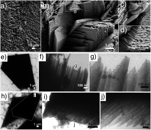 | ||
| Fig. 5 (a–d) SEM images of laminated CaP sheets obtained from the upper crust of a 2.5 mm thick H1 LC after 24 h of reaction; (e–j) TEM images of CaP bricks obtained from the layer 12–15 mm below the gel surface (pH 9–10) of a 35–40 mm thick H1 LC after 48 h of reaction. Gel recipe: L-4 (a–d), F-1 (e–j) in Table 1. Ammonia dose: (a–d) 800 mL 0.33 wt% NH3OH solution, and (e–j) 80 mL 35 wt% NH3OH solution. Squares and inserted letters mark the magnified region. | ||
To demonstrate the proposed construction principle of laminated CaP sheets, experiments using a Pluronic F127-based H1 LC phase with an additional sonication step prior to the reaction in the desiccator were conducted. The F127-based H1 LC contains butanol as the oil phase that would assist ammonia penetration through a thick gel system, thus causing a smooth pH rise within the gel layer.21 Furthermore, the additional sonication step introduces crystal nuclei to the system (Fig. S4a, ESI†), which then grow into larger crystal aggregates (Fig. S4b and c†). This approach allowed us to investigate the facets CaP subunit overgrowth that developed. Specifically, ca. 35–40 mm thick H1 LC samples (recipe: F-1, Table 1) were first subjected to sonication for 60 min, and then reacted in a concentrated ammonia atmosphere (80 mL 35 wt% NH3OH solution in pH beaker) for 48 h and from which the gel layers of 12–15 mm below the surface (pH 9–10) were collected. Fig. 5e and h show the typical TEM images of as-synthesized CaP “bricks”, in which a trapezium-like pentagon shape was presented. A higher magnification discloses the inner hierarchy of the shorter parallel “edge” of the trapezium (Fig. 5f, g, i and j).
The SEM studies depict the topography of such CaP “bricks” in detail (Fig. 6a–h), where smooth facets (a- and e-facet and the corresponding twin facets marked in Fig. 6a–d, g and h), grainy facets (b- and twin facets marked in Fig. 6a, f and g), striated facets (d- and twin facet marked in Fig. 6a, d, e and h), as well as laminated sides (c- and twin facets marked in Fig. 6a, c–f and h; occasionally exposed f- and twin facets marked in Fig. 6a and f) were presented together in the same brick. The narrow peaks in the XRD pattern confirm that the CaP brick comprises of highly crystalline brushite (Fig. 3c, phase pure). The a-, b-, d- and e-facet of the brick marked in Fig. 6a could be (hkl) indexed as (010), (111), (![[1 with combining macron]](https://www.rsc.org/images/entities/char_0031_0304.gif) 20), (11
20), (11![[1 with combining macron]](https://www.rsc.org/images/entities/char_0031_0304.gif) ) and the corresponding mirror facets with {010} as the twin plane, respectively, of pure brushite.22,23 We highlight that the c-side from SEM investigation (Fig. 6a) constantly happens to be the shorter parallel “edge” of the trapezium from TEM studies (Fig. 5e and h), where the laminated feature of the c-side (Fig. 6c–f and h) reconciles with the inner hierarchy presented on the shorter parallel “edge” in TEM images (Fig. 5f, g, i and j).
) and the corresponding mirror facets with {010} as the twin plane, respectively, of pure brushite.22,23 We highlight that the c-side from SEM investigation (Fig. 6a) constantly happens to be the shorter parallel “edge” of the trapezium from TEM studies (Fig. 5e and h), where the laminated feature of the c-side (Fig. 6c–f and h) reconciles with the inner hierarchy presented on the shorter parallel “edge” in TEM images (Fig. 5f, g, i and j).
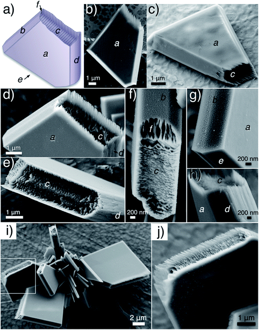 | ||
| Fig. 6 (a–h) SEM micrographs revealed the all-around details of the CaP bricks and (i and j) SEM images of a CaP object composed of several CaP bricks. Samples were prepared and collected with the same condition as the ones shown in Fig. 5e–j. Inserted italic letters index the different “facets” of the brick. Squares mark the magnified region. | ||
In addition to single brushite bricks, 15–25 micron-sized objects comprised of several bricks were observed abundantly in the sample (Fig. 6i and j). The evolution of these superstructures, disclosed by SEM, starts from a crystalline cluster formed by sonication-induced spontaneous precipitation within the highly saturated acidic precursor solution (Fig. S4a, ESI†). This then grows into large polycrystalline aggregates under further sonication (Fig. S4b and c†); and finally, each petal of the polycrystalline aggregate develops crystalline facets as well as a laminated structure on the c-side under an ammonia atmosphere (Fig. S4d, ESI†).
In an attempt to distinguish the laminated structure from the bulk single crystal of a brushite brick, the as-prepared brushite objects were subjected to a gentle grinding process using an agate mortar (5 min) in the presence of several drops of ethanol. Fig. 7a and c show the typical morphology of brushite objects after grinding. SEM images at higher magnification (Fig. 7b and d) unveil the c-side of brushite bricks after grinding, where the spaghetti-like patterns in Fig. 7b are the edges of disordered brushite subunits on the c-side after grinding. While in Fig. 7d, both bumpy solid surfaces (upper-left region) and attached distorted flakes with thickness on the order of 20 nm (lower-right region) on c-side are observed. The former can be assigned to the bulk single crystal of the brushite brick while the latter are distinctly the remaining brushite subunits after grinding. All of these features favor for our assumption of an epitaxially grown layer of brushite flake subunits on top of the brushite bulk brick, as illustrated in Scheme S1.† The epitaxial growth of ordered subunits from the crystalline bulk has been previously observed for calcium carbonate.24,25 Additionally, CaP with channel-like features resulting from the packing of brushite subunits has also been reported.26 However, these studies all require the interplay between ionic polymers and the crystals, while in our system, the structure is dependent solely on spatial confinement.
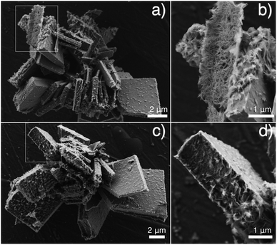 | ||
| Fig. 7 SEM images of the as-prepared CaP objects after gentle grinding (agate mortar, 5 min, with drops of ethanol). Squares mark the magnified region. | ||
Finally, SAXS analysis confirmed the presence of the LC phase (F127 based H1 LC, L64 based H2 and Lα LC, respectively) in the early stage of CaP structural development, as SAXS patterns (Fig. 8) with peak positions associated with the different LC structures were maintained in the collected gel layers (pH 7 or pH 8) after reaction for 48 h (Lα) or 72 h (H1 and H2), together with an initial slope indicating the particle formation within each LC.
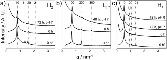 | ||
| Fig. 8 SAXS results of various LC gels before and after the reaction. (a) H2 LC gel prepared using L64 (recipe: Table 1 L-1), (b) Lα LC gel prepared using L64 (recipe: Table 1 L-2), and (c) H1 LC gel prepared using F127 (recipe: Table 1 F-1). Gel thickness: 35–40 mm. Samples were exposed to a NH3 atmosphere (300 mL 35 wt% NH3OH solution in pH beaker) for 0 and 48 h or 72 h and were collected according to pH (0 h* refers to the LC gel prepared without Ca and P sources, while the rest refers to LC gels prepared with a precursor concentration of 0.84 M Ca2+). SAXS data have been vertically shifted for clarity. | ||
In the current system, ACP, DCPA and DCPD are the three major phases competing in the process of precipitation. ACP, with the isotropic nature, i.e. possibility to replicate any shape, is favorable for controlled morphogenesis, while the anisotropicity of DCPs encumbers it, as the preferential growth could break down the LC template organized via hydrophobic interaction.11 We show that it is possible to precisely template CaP in H2 (Fig. 2c, e and f) and Lα (Fig. 4b and c) LC phases and we associate this to the negative (H2) or flat curvature (Lα) of the aqueous domains, as they offer sufficient spatial regulation on the growth of ACP and even DCPs. However, accurate CaP replication of the H1 LC structure was not attainable, due to the positive curvature of the aqueous domain in the H1 phase, providing less spatial confinement. Never the less, we demonstrate that LC re-assemblability provides the template with the ability to build up crystalline CaP with organized nano-patterns (Fig. 5 and 6).
4. Conclusion
In summary, crystalline CaP nanowires and nanosheets (both ACP and DCP) that respectively replicate a H2 and Lα LC have been synthesized by a simple gas diffusion method with commercially available reactants. In addition, the method can be used to produce brushite objects with superstructure in a H1 LC. The generation of a laminated structure on brushite objects is facet-specific and possibly the result of brushite subunit epitaxial overgrowth. Control over the CaP morphology was achieved solely by spatial confinement, allowing the possibility of this methodology to be used with alternative components.Conflict of interest
The authors declare no competing financial interest.Acknowledgements
We acknowledge the Swedish Research Council and NanoSphere Centre/Formas for funding. We also thank MAX-lab (Lund, Sweden) for the allocation of beam time and assistance with SAXS measurements.References
- A.-W. Xu, Y. Ma and H. Colfen, J. Mater. Chem., 2007, 17, 415 RSC.
- H. A. Lowenstam and S. Weine, On Biomineralization, Oxford University Press, New York, 1989 Search PubMed.
- B. R. Heywood and S. Mann, Adv. Mater., 1994, 6, 9 CrossRef CAS.
- S. Weiner and P. M. Dove, An Overview of Biomineralization Processes and the Problem of the Vital Effect, in Reviews in Mineralogy and Geochemistry; Biomineralization, ed. P. M. Dove, J. J. De Yoreo and S. Weiner, Mineralogical Society of America, 2003, vol. 54, p. 1 Search PubMed.
- S. V. Dorozhkin and M. Epple, Angew. Chem., Int. Ed., 2002, 41, 3130 CrossRef CAS.
- M. Vallet-Regí and E. Ruiz-Hernández, Adv. Mater., 2011, 23, 5177 CrossRef PubMed.
- R. Z. LeGeros, Z. Kardiol., 2001, 3, 116 Search PubMed.
- L. J. Wang and G. H. Nancollas, Chem. Rev., 2008, 108, 4628 CrossRef CAS PubMed.
- L. Wang and G. H. Nancollas, Dalton Trans., 2009, 2665 RSC.
- A. Navrotsky, Proc. Natl. Acad. Sci. U. S. A., 2004, 101, 12096 CrossRef CAS PubMed.
- H. Cölfen, Angew. Chem., Int. Ed., 2008, 47, 2351 CrossRef PubMed.
- S. R. Hall, H. Bolger and S. Mann, Chem. Commun., 2003, 2784 RSC.
- H. Tlatlik, P. Simon, A. Kawska, D. Zahn and R. Kniep, Angew. Chem., Int. Ed., 2006, 45, 1905 CrossRef CAS PubMed.
- X. Wang, J. Zhuang, Q. Peng and Y. D. Li, Adv. Mater., 2006, 18, 2031 CrossRef CAS.
- F. Nudelman, K. Pieterse, A. George, P. H. H. Bomans, H. Friedrich, L. J. Brylka, P. A. J. Hilbers, G. de With and N. A. J. M. Sommerdijk, Nat. Mater., 2010, 9, 1004 CrossRef CAS PubMed.
- F. Nudelman and N. A. J. M. Sommerdijk, Angew. Chem., Int. Ed., 2012, 51, 6582 CrossRef CAS PubMed.
- K. Bleek and A. Taubert, Acta Biomater., 2013, 9, 6283 CrossRef CAS PubMed.
- S. Eftekharzadeh and S. I. Stupp, Chem. Mater., 1997, 9, 2059 CrossRef CAS.
- W. X. He, P. Kjellin, F. Currie, P. Handa, C. S. Knee, J. Bielecki, L. R. Wallenberg and M. Andersson, Chem. Mater., 2012, 24, 892 CrossRef CAS.
- P. Alexandridis, U. Olsson and B. Lindman, Macromolecules, 1995, 28, 7700 CrossRef CAS.
- P. Holmqvist, P. Alexandridis and B. Lindman, Langmuir, 1997, 13, 2471 CrossRef CAS.
- F. Abbona, F. Christensson, M. F. Angela and H. E. L. Madsen, J. Cryst. Growth, 1993, 131, 331 CrossRef CAS.
- J. L. Giocondi, B. S. El-Dasher, G. H. Nancollas and C. A. Orme, Philos. Trans. R. Soc., A, 2010, 368, 1937 CrossRef CAS PubMed.
- D. Volkmer, M. Harms, L. Gower and A. Ziegler, Angew. Chem., Int. Ed., 2005, 44, 639 CrossRef CAS PubMed.
- H. Imai, T. Terada and S. Yamabi, Chem. Commun., 2003, 484 RSC.
- A. Shkilnyy, J. Brandt, A. Mantion, O. Paris, H. Schlaad and A. Taubert, Chem. Mater., 2009, 21, 1572 CrossRef CAS.
Footnote |
| † Electronic supplementary information (ESI) available: Experimental setup, the supplementary micrographs of CaP particles synthesized in H2 LC, SEM images of the introduction of CaP nuclei in H1 gel, and scheme of the proposed mechanism for CaP brick/object formation. See DOI: 10.1039/c4tb00095a |
| This journal is © The Royal Society of Chemistry 2014 |

