 Open Access Article
 This Open Access Article is licensed under a
 Creative Commons Attribution 3.0 Unported Licence
Chemical strategies for the presentation and delivery of growth factors
Jordi
Cabanas-Danés
,
Jurriaan
Huskens
and
Pascal
Jonkheijm
*
Molecular Nanofabrication Group, Department of Science and Technology and MESA+ Institute for Nanotechnology, University of Twente, P.O. Box 217, 7500 AE, Enschede, Netherlands. E-mail: p.jonkheijm@utwente.nl; Tel: +31 534892987 Web: www.jonkheijm-group.nl
First published on 8th July 2013
Abstract
Since the first demonstration of employing growth factors (GFs) to control cell behaviour in vitro, the spatiotemporal availability of GFs in vivo has received continuous attention. In particular, the ability to physically confine the mobility of GFs has been used in various tissue engineering applications e.g. stents, orthopaedic implants, sutures and contact lenses. The lack of control over the mobility of GFs in scaffolds jeopardizes their performance in vivo. In this feature article, an overview is given on how to effectively present GFs on scaffolds. In the first part, non-covalent strategies are described covering interaction motifs that are generic to direct GF immobilization. In the second part, covalent strategies are described emphasizing the introduction of reactive groups in existing biomaterials. The feature article ends with a description of strategies based on the physical entrapment of growth factors.
Introduction
Growth factors (GFs) are a powerful class of signalling molecules capable of regulating cellular fate, including adhesion, migration, proliferation and differentiation, and thus offering the potential to coordinate events like tissue formation, maintenance or regeneration.1 Although GF signalling is initiated directly upon forming stable complexes with GF receptors, which reside on the cell surface, complete gene expression is a much slower process. Therefore, control over the presentation of GFs in biomaterials is required not only in terms of retained biological activity upon inclusion of GFs into these materials, ideally with optimized accessibility to and orientation of the GFs, but also in terms of extended longevity of the presence of GFs to obtain efficient cell response.Endogenously, the mobility of GFs is confined by the extracellular matrix (ECM). Throughout the last few decades, sophisticated approaches have been developed incorporating features derived from the ECM.2 Many of these approaches consist of tethering GFs onto the surface of a (bio)material to achieve control over their spatial distribution. Other approaches rely on blending GFs into biopolymers to achieve temporal control over the GF delivery. Notwithstanding the progress in the development of employing GFs in scaffolds, the in vivo performance of such GF-loaded scaffolds in e.g. orthopaedic implants, stents, sutures and contact lenses, is still challenged by the necessary control over the mobility of GFs in scaffolds.
We present an overview of the methodologies presented in the literature for the presentation of GFs to cells at the cell–material interfaces. Selected examples are described that emphasize the different types of strategies irrespective of the type of GF, (bio)material or application involved. Highlighted examples range in using non-covalent interactions, covalent attachment and matrices with the common goal of controlling the spatiotemporal evolution of the GFs.
Non-covalent GF immobilization
The strategy used by the ECM to control the mobility of GFs and thereby to ensure proper cell functioning is based on non-covalent interactions between different parts of the ECM and GFs. When non-covalent interactions are non-directional, including for example ionic bonds, hydrophobic and polar interactions, typically GFs are physisorbed. However, non-covalent interactions exist that are directional, including for example hydrogen bonds and host–guest interactions.3 The advantage over non-directional interactions lies in the specificity and directionality of the supramolecular interaction and the tunability of the type and number of interaction motifs. In addition to a homogeneous and oriented attachment, the reversibility of immobilization is attractive to tune the extent of delivery in time. Typically the ECM binds GFs through a combination of directional and non-directional interactions to ensure the optimal orientation and temporal availability of the GFs.In recent years, researchers have adopted affinity tags for immobilizing GFs onto surfaces. Many of the interactions currently used for this purpose have been originally developed for protein applications.4
Nitrilotriacetic acid–Ni(II)–hexahistidine interactions
Proteins bearing an engineered hexahistidine (His6)-tag are employed for the site-specific immobilization on Ni(II)–nitrilotriacetic acid (NTA)-functionalized surfaces. NTA is a tetradentate ligand that forms an octahedral complex with Ni(II) ions, leaving two binding sites available for binding to a His6-tag. The binding affinity is usually in the range of 106–107 M−1.5 This immobilization can be easily reversed by the addition of a competitive metal binding agent (e.g. imidazole or ethylenediaminetetraacetic acid (EDTA)). Many researchers have taken advantage of this system for the binding of fluorescent proteins, antibodies, virus proteins, and GFs to surfaces for a variety of applications.5,6Iwata and co-workers employed a C-terminal His6-tag on the recombinant epidermal growth factor (EGF) to immobilize the EGF onto Ni(II)–NTA surfaces.7 First, the authors described a method to build arrays of Ni(II)–NTA on gold-coated glass substrates for the construction of EGF–His6 microarrays.7a,b Briefly, a 1-hexadecanethiol self-assembled monolayer (SAM) was formed that covered the entire surface. Then, part of the SAM was photolytically removed in a pre-defined pattern and these bare gold areas were subsequently functionalized with 11-mercapto-1-undecanoic acid. Further derivatization into active succinimidyl esters was achieved upon reaction with N-hydroxysuccinimide (NHS) in the presence of N,N′-dicyclohexylcarbodiimide (DCC).7 Reaction with an appropriate NTA derivative and incubation with NiSO4 yielded a microarray of Ni(II)–NTA-terminated spots.7 After confirming the presence of EGF within the array spots, neural stem cells (NSCs) were cultured on the platforms. While NSCs seeded on chelated EGF–His spots adhered and proliferated to a substantial number, NSCs seeded on controls of covalently immobilized EGF spots were lacking aggregation.7 These results demonstrated that cell aggregation, proliferation and phenotype maintenance were mediated more efficiently on chelated EGF–His surfaces as compared to those with the covalently tethered EGF.7 Most likely favourable interaction between the EGF and the specific EGF receptors (EGFRs) on the cell surface takes place on EGF–His surfaces. In a follow-up study, the authors were able to relate cell activity with the control over orientation, conformation and surface stability when immobilizing EGF via His-tag technology in comparison with the covalently bound EGF via NHS-chemistry.7c Infrared absorption spectroscopy analysis of anchored EGF–His suggested that chelated EGFs retain the same conformation both in solution as well as for physically adsorbed EGF–His (through ionic bonds). Contrarily, the covalently immobilized EGF exhibited an altered spectrum being indicative of protein denaturation. In addition, NSCs cultured on immobilized EGF–His presented a negligible expression of the βIII neuronal marker and the astrocytic GFAP marker indicating that on these regions the pluripotent phenotype is maintained. In contrast, cells outside the pattern expressed high levels of both βIII and GFAP while the expression of the stem cell marker nestin was reduced. Taken together, these results showed a technology to create microarray surfaces to study the protein-based cell function and that immobilizing EGFs employing directional interactions is advantageous to physisorption and (random) covalent chemistry.
Biotin–streptavidin interactions
Similar to the previous strategy, the interaction between biotin and streptavidin (SAv) has been broadly used to specifically bind proteins to materials.5 This interaction leads to highly stable and nearly irreversible complexes with a Ka of up to 1015 M−1. An example of the use of this strategy to immobilize GFs was presented by Groves et al. in an attempt to understand ligand–receptor interactions.8 Their approach consisted of the use of a fluid-supported lipid bilayer (SLB) for displaying soluble ligands to cells.8 In this manner, the authors claimed to obtain a system combining a solution behaviour (local concentration can be enriched by reaction–diffusion processes) and a solid behaviour (with control over the spatial location of the ligands). To prove the concept, a SLB was doped with a biotin-modified phosphatidyl derivative to allow first binding of SAv and subsequently binding of biotinylated EGFs (Fig. 1).8 | ||
| Fig. 1 Fabrication of the EGF–SLBs on glass substrates. The EGF was conjugated to Alexa-647-labeled SAv and the SLB contained 7-nitrobenz-2-oxa-1,3-diazol-4-yl (NBD). FRAP experiments indicated binding of EGFs. SLBs were used to study the interaction between EGFs presented to the specific EGFR on the cell membrane and cellular signaling. The Attofluor cell chamber was used to maintain the stability of SLBs while immersed in a NaCl solution.8 Copyright © 2006 Wiley-VCH Verlag GmbH & Co. KGaA, Weinheim. | ||
Successful binding of the EGF to the SLB was demonstrated by the reduced fluidity of the EGF–SLB in comparison to a bare SLB using fluorescence recovery after photobleaching (FRAP) experiments.8 Cells from the human breast epithelial cell line (MCF-10a cells) were used to assess the biological activity of the platforms. Cells seeded on an EGF–SLB were incubated for 20 h. After this time, cell attachment was visible on EGF–SLBs and not on bare SLBs.8 Moreover, when a competing antibody for EGF-receptor tyrosine kinase (EGFR) was added, cell attachment was reduced in the same manner as for platforms in the absence of EGF. These results suggested that cell attachment is mediated by binding of EGF to EGFR on SLBs. To verify these results, cells were treated with Tarceva, a kinase inhibitor of EGFR, which resulted in a similarly poor cell attachment, confirming that activation of EGFR kinase activity is required for cell attachment. EGF clustering was observed 100 min after plating and further enlarged in time indicating that focal adhesions are required for cell attachment.8 Additionally, endocytosis of the complex EGF–EGFR was detected indicating the progression of cell signalling. When the intrinsic SLB mobility was reduced by using 1,2-dipalmitoyl-sn-glycero-3-phosphocholine, cell spreading was also reduced at a similar surface concentration of GF.8 Moreover, fewer EGF clusters were observed for the low mobility EGF–SLB.8 These results indicated that the layer mobility facilitates clustering of EGFs and ultimately cell adhesion and spreading.
In another example given by Park and co-workers the biotin–SAv strategy was employed for cell transfection purposes.9 In this case the primary amine groups of EGF were used to couple NHS–PEG–biotin to yield mono-, di-, and tri-pegylated EGF species. Then, polyethyleneimine (PEI) and luciferase plasmid DNA were mixed to form 90 nm positively charged polyelectrolyte complex particles (PEI–DNA).9 These particles were coated electrostatically with SAv yielding an effective diameter from 100 to 200 nm for a SAv–DNA molar ratio of 100. These SAv–PEI–DNA complexes were used to form supramolecular complexes with EGF–PEG–biotin conjugates. However, only when mono-pegylated EGFs were bound to the complexes, stable nanoparticles were produced, while multi-pegylated EGFs led to abrupt aggregation at a biotin–SAv molar ratio of 4.9 This DNA delivery platform represented an optimal alternative to overcome DNA enzymatic degradation when incubated with nuclease, suggesting that entrapped plasmid DNA was effectively protected. Finally, the particles were used to successfully transfect human epidermoid carcinoma cells which over-express EGF receptors.9 The transfection efficiency of PEI–DNA complexes was dependent on surface charge. When the surface charge became less positive, for example by the interaction with SAv (EGF left out), adsorptive endocytosis decreased resulting in a reduced transfection efficiency.9 When transfection was mediated by the specific interaction between EGF and EGF receptors, a good transfection efficiency was observed.9
In another recent example exploiting the interaction between biotin and SAv, M13 phages were modified to express biotin-like peptide sequences (HPQ) and/or integrin binding sequences (RGD) on their coat proteins for the immobilization of SAv-conjugated basic fibroblast growth factor (FGF-2) and nerve growth factor (NGF).10 Some of the advantages of presenting binding points for GFs on phages are that the identical copies of the phage can be easily produced on a large scale via bacterial amplification, and the resulting phage can be used to build nanofibrous networks without using additional fabrication techniques. FGF-2 and NGF could then be bound to the phage in order to successfully regulate proliferation and differentiation of hippocampal neural progenitor cells (NPCs) in a synergistic manner together with RGD.
Shoichet's group developed an approach for the efficient spatially controlled immobilization of sonic hedgehog (SHH) and ciliary neurotrophic factor (CNTF) to promote differentiation of retinal precursors.11 In their case, a 3D thiol-agarose scaffold was protected with the photolabile coumarin moiety which upon two-photon irradiation could be cleaved yielding exposed thiol groups only in the illuminated areas. Those thiol groups could be further modified through the Michael addition of maleimide terminated SAv or barnase to take advantage of the orthogonal non-covalent binding pairs SAv–biotin (Kd = 10−15 M) and barnase–barstar (Kd = 10−14 M), respectively. In this way, once the hydrogel was functionalized with both units, barstar–SHH and biotin–CNTF could self-sort upon supramolecular interactions with their binding partners (Fig. 2a).11 After analysing the relationship between the scan number and concentration of immobilized GFs in independent experiments for each binding pair, the technique was used to simultaneously immobilize the two proteins following the process in Fig. 2a. Confocal microscopy was used to sequentially irradiate two different regions while functionalizing them with either barnase or SAv.11 Since the coumarin protective group has an intrinsic fluorescence, functionalization could be followed by the loss of fluorescence (Fig. 2b). Co-functionalization could be observed by using two different Alexa fluorescent dyes for labeling the GFs (Fig. 2c–e). Finally, the bioactivity of the non-cytotoxic scaffolds was confirmed in vitro using retinal precursor cells (RPCs) since expression of relevant markers was found.11
 | ||
| Fig. 2 (a) Two-photon irradiation strategy to simultaneously immobilize barstar–SHH and biotin–CNTF. (b) Loss of the coumarin protection by two-photon irradiation and maleimide functionalization. While the large broken circle corresponds to maleimide–barnase, the smaller oval corresponds to maleimide–SAv. (c–e) Confocal images corresponding to different views of the two-regions functionalized with barstar–SHH–Alexa-488 (green) and biotin–CNTF–Alexa-633 (red). Adapted by permission from Macmillan Publishers Ltd: Nature Materials. Shoichet et al.11 Copyright © 2011. | ||
Peptide amphiphiles
Peptide amphiphiles (PAs) combine the amphiphilic features from surfactants with peptide sequences possessing biological functions to self-assemble into 1D nanostructures (Fig. 3) under physiological conditions.12 Moreover, they represent a highly robust construction since differences in peptide sequence have a minimum impact on the self-assembly process. Throughout the last few decades, Stupp et al. have pioneered the development of such supramolecular PA nanostructures for use in tissue regeneration.13 For example, PA-fibers were employed for direct binding and delivery of transforming growth factor β1 (TGF-β1).14a One PA-fiber consists of a PA bearing at the N-terminus the HSNGLPL epitope (identified by phage display) with a high binding affinity to TGF β1 (ref. 14b) mixed with another PA bearing a biologically passive sequence that acts as a filler peptide to control the distribution and accessibility of the binding epitopes (Fig. 3). These PA-fibers could support the viability and chondrogenic differentiation of mesenchymal stem cells (MSCs). First, the authors demonstrated a slower release of TGF-β1 in the case in which pre-loaded nanofibers containing 10 mol% of TGF-β1-binding PA were used in comparison to TGF-β1 supplemented to fibers assembled from only filler PA.14b MSCs were not only viable within the PA gel in vitro but they also showed an increased expression of cartilage markers in the presence of TGF-β1 for TGF-β1-binding PA fibers compared to fibers of filler PA after 4 weeks of culture.14b The in vivo potential of the fibers was further evaluated in full thickness chondral defects in a rabbit model. The defects were filled with the PA fibers and after 12 weeks of treatment, macroscopic differences were observed for defects treated with TGF-β1-binding PA fibers both with and without TGF-β1 compared to those treated either with TGF-β1 alone or with non-bioactive filler PA (Fig. 3d).14b For the TGF-β1 loaded as well as unloaded TGF-β1-binding PA fibers, the defect was nearly filled by new tissue similar in color and texture to the surrounding cartilage.14b The fact that unloaded TGF-β1-binding PA fibers were able to regenerate the tissue in the defects as effectively as in the presence of exogenous TGF-β1 was explained by the ability to bind endogenously presents TGF-β1, e.g. from the bleeding marrow or surrounding synovial fluid. In another example using a supramolecular material, PA was used as a scaffold to bind platelet-derived growth factor BB (PDGF-BB), vascular endothelial growth factor A (VEGF-A), FGF-2 and angiopoietin-1 (Ang-1).15a A prolonged PDGF-BB delivery was found for up to 14 days when delivered together with PA gel with potential applications in the preservation of myocardial function.15a Moreover, FGF-2 was also bound to the PA matrix by mixing the GF with a PA aqueous solution resulting in the in situ formation of a 3D scaffold inducing angiogenesis in vivo and in vitro.15b Lee et al. were able to decorate the periphery of the PA fibers with biotin to allow the specific interaction with SAv and biotinylated insulin-like growth factor 1 (IGF 1).16 The presence of IGF-1 bound to these PA-fibers was 5-fold higher than to PA-fiber lacking biotin.18 These PA-fibers were used to treat rat neonatal cardiac myocytes and Akt phosphorylation was analyzed as it represents a downstream target of IGF-1 signaling. Fibers loaded with biotinylated IGF-1 induced Akt phosphorylation 5-fold after prolonged delivery for 14 days compared to either PA-fibers alone or untethered IGF-1.16 When the IGF-1 loaded fibers were delivered in vivo to the myocardium of rats, an enhanced GF retention was observed up to 28 days in comparison to the soluble one, which was rapidly eliminated.16 Additionally, after 14 days Akt activation was detected in tissues with tethered IGF-1 but not with the controls without tethered IGF-1.16 Tethered IGF-1 further reduced implanted cardiomyocyte apoptosis while increasing cell growth was observed.16 | ||
| Fig. 3 Design of PAs with chondrogenic potential. Chemical structure of (A) TGF-β1-binding PA and (B) filler PA. (C) Illustration of the resulting self-assembled nanofibers displaying the accessible TGF-β1-binding sequences. (D) TGF-β1 release profile for nanofibers composed of only filler PA or filler PA containing a 10% of TGF-β1-binding PA (TGFBPA).14a Copyright © 2010. | ||
Immobilized peptides
Recently, our group reported the covalent co-immobilization of a cysteine-terminated TGF-β1-binding peptide sequence (CLPLGNSH) together with a peptide sequence with a binding affinity for collagen type-II (CLRGRYW) therefore conferring cartilage regeneration and targeting properties respectively to the biosurfaces.17 In brief, a fluorogenic monolayer was used to directly visualize the step-wise orthogonal covalent co-immobilization of both peptides. Subsequently, TGF-β1 and collagen type-II could be self-sorted from a mixture in a region-selective manner resulting in a bi-functional protein platform. In addition, surfaces with immobilized TGF-β1-binding peptide pre-loaded with the GF showed excellent bioactivity in combination with human articular chondrocytes (HACs) and stimulated expression of early chondrogenic markers.17The use of systems promoting specific biological response without the need for exogenous GFs or transplanted cells was demonstrated by Kiessling and co-workers. The fabricated surfaces presented covalently attached peptides with binding affinity to TGF-β1 receptors.18 These platforms were reported not to compete with the GF but rather to sensitize bound mouse mammary gland cells (NMuMG) to subpicomolar concentrations of endogenous TGF-β (Kd ≪ 5 pM).18
Heparin-based systems
In the late 1990s, an increasing interest in the interactions between proteins and glycosaminoglycans (GAGs) arose. In particular, heparin and heparan sulfate interactions with proteins with relevant biological functions have been exhaustively studied to date and several reviews have appeared on the topic.19 Heparin and heparan sulfate, both present in the ECM, are sulfated, linear, unbranched polysaccharides structurally composed of disaccharide repeated units.19b They contain dimers of uronic acid and 1,4-linked glucosamine. While the major occurring disaccharide sequences in heparin contain three sulfonate groups, heparan sulfate contains only an average of less than 1 per disaccharide.19aO-Sulfated saccharides have been found both in heparin and heparan sulfate for the specific interaction with various members of the FGF family.20 Heparin exists primarily as a helical structure. The key of the specificity of the interaction of heparin with proteins is suggested to rely on a defined orientation and distribution pattern of the charges of both the sulfonate and carboxyl groups at the exterior of the helix.19b Several consensus sequences including basic and hydropathic (neutral and hydrophobic) amino acid residues with turns in the secondary structure (which bring basic amino acid residues into proximity) have been frequently reported for the interaction with a multitude of GFs.19aAs an example, Linhardt and co-workers presented a collection of studies regarding the interaction of acidic FGF-1, basic FGF-2 and TGF-β1 with heparin.19a After structural analysis of the three GFs, a common motif was found: TXXBXXTBXXXTBB (where T defines a proline turn, B a basic amino acid residue such as arginine or lysine (or occasionally a hydrogen bonding glutamine) and X a hydropathic residue). This interaction resulted in a complex with a dissociation constant in the 10−9 M order for FGF-2 complexed with heparin.21 Moreover, competitive binding studies in the presence of different concentrations of NaCl served to determine that only 30% of the binding free energy is caused by pure electrostatic interactions while the rest of the contributions rely mostly on hydrophobic interactions and hydrogen bonding through the hydroxyl groups present in heparin.21 As can be seen above, one of the most well studied heparin-binding proteins is FGF with a high affinity for heparan sulfate proteoglycans on the cell surface. FGF binds specifically to cell surface receptors called fibroblast growth factor receptors (FGFRs) and, interestingly, via multiple interacting points. Therefore, for the success of the interaction a simultaneous ternary complex formation is required.22 Within this context, heparan sulfate mediates FGFR dimerization, necessary to initiate signal transduction, by binding several FGFs next to each other. Depending on the FGF and FGFR pairs, the complex will be 1![[thin space (1/6-em)]](https://www.rsc.org/images/entities/char_2009.gif) :1:1 interacting with another 1:1:1 and thus resulting in a 2:2:2 complex for the pair FGF-2 and FGFR-1 or 2:2:1 for FGF-1 and FGFR-2 with heparin as reported by Schlessinger et al.23 and Pellegrini et al.24 respectively (Fig. 4).
:1:1 interacting with another 1:1:1 and thus resulting in a 2:2:2 complex for the pair FGF-2 and FGFR-1 or 2:2:1 for FGF-1 and FGFR-2 with heparin as reported by Schlessinger et al.23 and Pellegrini et al.24 respectively (Fig. 4).
 | ||
| Fig. 4 Structures of FGF (green)–FGFR (yellow)–heparin (balls) complexes for FGF-2:FGFR1:heparin (left) and FGF-1:FGFR2:heparin (right). Balls (heparin) represent S (yellow), O (red) and N (blue) atoms.19b Copyright © 2002 Wiley-VCH Verlag GmbH, Weinheim. | ||
Examples describing the interaction of heparin with isoforms of the vascular endothelial growth factor (VEGF), TGF-β1, PDGF and EGF have been presented by Capila and Linhardt as well.19b These invaluable efforts in exploring and characterizing in great detail the interactions between several growth factors and heparin gave origin to a multitude of applications in the tissue engineering field.2d,4 Some studies used approaches to incorporate heparin to a broad range of existent biocompatible materials in order to improve their GF retention, presentation and delivery properties. In one example heparin was modified with methacrylate groups in order to be co-polymerized with dimethacrylated PEG yielding a hydrogel for the localized delivery of biologically active FGF-2 for up to 5 weeks. The complexed FGF-2 was able to promote adhesion, proliferation and osteogenic differentiation of human mesenchymal stem cells (hMSCs).25 Bone morphogenetic protein 2 (BMP-2) and RGD were also presented to hMSCs by this type of hydrogel resulting in the production of increased levels of osteogenic markers.26 In another example, hyaluronic acid, gelatin and heparin were modified with thiol groups and co-cross-linked with poly(ethylene glycol) diacrylate (PEGDA). These hydrogels containing only 0.3% of heparin in their composition showed sustained release of either VEGF or FGF-2 and improved in vitro neovascularization properties, when compared to hydrogels without co-cross-linked heparin.27
Titanium surfaces were also functionalized with heparin for the immobilization of BMP-2 (ref. 28) and VEGF.29 In a recent example, the activity of heparin-bound VEGF was compared to that of VEGF tethered covalently to the same type of surface.29b VEGF was covalently immobilized on Ti-foils coated with hyaluronic acid–catechol or non-covalently on heparin–catechol. The Ti-surfaces were used to evaluate the cell response using endothelial cells (ECs) and osteoblasts. Although similar surface densities of immobilized GFs were achieved following both the covalent and non-covalent strategies, the EC response of the covalently immobilized VEGF was significantly reduced when compared to the heparin-bound VEGF.29b In addition, the latter case led to enhanced mineralization in osteoblast/EC co-cultures. Moreover, a reduced bacterial infection was observed in the studies which could be related to the highly hydrophilic and negatively charged nature of the heparin-bound Ti surfaces.29b
A range of biomaterials has been covalently cross-linked with heparins. For example, alginate30 and poly(lactic-co-glycolic acid) (PLGA)31 are covalently cross-linked with FGF-2 binding heparin and these materials showed improved in vivo and in vitro angiogenesis properties when compared to the materials without heparin. A dendrimer, modified with EGF-binding heparin, was cross-linked with a collagen gel and successfully used for inducing the proliferation of human cornea epithelial cells (HCECs).32 The surface of electrospun fibers of poly(ε-caprolactone) (PCL)/gelatin was covalently modified with heparin for the binding of PDGF-BB. The fibers showed prolonged proliferation and smooth muscle cells (SMCs) could infiltrate extensively into the heparin-modified scaffold.33 Polymeric micelles of a block copolymer of Tetronic®–PCL–heparin were prepared by an emulsion and solvent evaporation method as an injectable vehicle for long-term delivery of FGF-2 showing an excellent performance of GF delivery properties.34
An elegant example based on the use of natural matrices functionalized with heparin was presented by Hubbell's group for the controlled delivery of FGF-2 (ref. 35) or β-NGF for nerve regeneration technology making use of heparin–GF interactions.36 Although β-NGF has only a weak interaction with heparin,37 the authors postulated that a basic domain present in β-NGF or other neutrophins such as brain-derived neurotrophic factor (BDNF) and neurotriphin-3 (NT-3) could actually interact with heparin while slowing down the diffusion-based protein release from a fibrin matrix. In order to demonstrate it, fibrin was decorated with heparin-binding peptides covalently cross-linked to the matrix by the enzymatic activity of factor XIIIa. Those peptides could subsequently sequester heparin within the fibrin matrix. After loading the matrix with β-NGF, its release was studied and compared with a case with both heparin-binding peptides and heparin being absent. Without the heparin-binding and heparin components present in the matrix, the majority of the GF was released within a day, whereas in the presence of the components, only 50% of the initial amount of β-NGF was released within a day while 30% of the initial GF remained stagnant in the matrix after 15 days. In addition, a neuronal cell culture model was used to assess the performance of β-NGF, BDNF, or NT-3 presented via the heparin-based delivery system resulting in a significant enhancement of neurite extension only when heparin-binding peptides, heparin and GFs were present in comparison to unmodified fibrin with β-NGF in the cell culture medium.
Another biomimetic anchoring method has been recently presented for the immobilization of FGF-2 and FGF-8 that enables a switchable GF bioavailability.38 Here conducting poly(3,4-ethylenedioxythiophene) (PEDOT) films were formed on poly(ethylene terephthalate) (PET) substrates by the oxidative electropolymerization of EDOT, resulting in a net positively charged polymer. This property was used by Teixeira and co-workers to form a stable electrostatic complex between the negatively charged heparin and the positively charged polymer backbone. The electrochemical responsiveness of the system was described (Fig. 5). When an electrochemical reduction process was applied to the system, PEDOT became nearly neutral, decreasing the ionic binding of heparin to PEDOT, and when the system was electrochemically oxidized, fully oxidized PEDOT restored the tight original complex with heparin.38 FGF-2 could be bound to the negatively charged heparin and upon applying the PEDOT reductive potential the heparin complexation to the PEDOT film was disrupted, thereby releasing FGF-2.38 The authors found significant stabilization of FGF-2 against enzymatic degradation when compared to soluble FGF-2, which represents a clear advantage to a daily soluble dose required in cultures of NCSs.38 In addition the authors found that the control over the bioavailability of the GF via an electrochemical stimulus resulted either in undifferentiated (Fig. 5c) or differentiated (Fig. 5d) NSC cells.
 | ||
| Fig. 5 Schematic representation of the two redox states of the electro-responsive GF presentation system. (a) When reduced, PEDOT becomes neutral while weakening the electrostatic interaction with heparin which gains then an increased freedom of movement for the interaction of the heparin-immobilized GF with specific cell receptors. (b) Contrarily, when oxidized, PEDOT becomes positively charged with a high affinity for the anionic sulfonate groups of heparin resulting in a tight structure that hampers the interaction of heparin-bound GFs with cells. The two states have a clear impact on NSC differentiation. (c) While interaction with FGF-2 prevents cell differentiation while cells remain proliferative, (d) a restricted contact with the GF leads to astrocytic differentiation.38 Copyright © 2011 Wiley-VCH Verlag GmbH & Co. KGaA, Weinheim. | ||
Stupp and co-workers have been exploring the potential of heparins by decorating the periphery of their PAs with heparins as pro-angiogenic matrices.39 After mixing two aqueous solutions: i.e. one solution containing a PA with a positively charged peptide sequence (i.e. LRKKLGKA), which is able to bind to heparin chains (Ka = ∼107 M−1)39a and another solution of heparin with or without FGF-2 and VEGF, PA–heparin fibers were formed. These PA–heparin fibers were reported to bind FGF-2 and delay its release in comparison to PA in the absence of heparin. The FGF-2 loaded PA-fibers resulted in enhanced vascularization of a rat cornea in comparison with samples using PA without heparin or using a PA-fiber made of a scrambled version of the heparin-binding sequence (i.e. LLGARKKK).39b
HBPAs were also used by the same groups to deliver angiogenic GFs to extrahepatic islet isografts in diabetic mice while increasing vascular density in the transplant site. In such a way improved islet engraftment and insulin production was achieved while reducing the time required to achieve normoglycemia.39c,d Finally, in a more recent example, these authors combined the use of HBPAs with hyaluronic acid to create a membrane at their interface.39e This membrane has three regions: an amorphous layer, a region with PA fibers parallel to the contact interface and a zone with fibers aligned perpendicular to the interface.40 These membranes, which can form in situ, were successfully used to deliver VEGF and FGF-2 in vitro and promote angiogenesis in vivo.
Recently, Tekinay, Guler and co-workers designed PA-fibers that contain carboxylic acid, hydroxyl and sulfonate groups to mimic the binding function of heparin.41 A binding constant of Ka = 106 M−1 was found for the VEGF binding to the PA-fibers containing all three charged groups which compares favorably to the VEGF binding to heparin. SO3−–PA nanofibers did not reveal any VEGF binding but the PA fibers with SO3−, COOH and OH groups exhibited slow VEGF release rates within the narrow VEGF therapeutic region.41 Culturing human umbilical vein (hUV)ECs on such multi-charged PA-fibers led to the formation of capillary-like structures without the presence of any exogenous GF. In vivo neo-vascularization of rat corneas was successfully achieved with GF amounts several times lower than the ones used in the literature when in combination with HMPA, providing new opportunities for angiogenesis and general tissue regeneration. The usability of the system was lately extended to binding other GFs such as hepatocyte growth factor (HGF), BMP-2 and NGF with different affinities.42
As described above, the interaction between heparin and GFs can be used to synthesize heparin-mimicking materials in which heparin is eventually absent.43 In particular, the example presented by Maynard's group shows a method to create micro- and nanoarrays of FGF-2 and VEGF by using electron beam (e-beam) lithography (Fig. 6).43b First, the authors designed a novel synthetic polymer which mimicked heparin to overcome the limitations of costumed heparin synthesis.43b Poly(sodium 4-styrenesulfonate)-co-poly(ethylene glycol methacrylate) (PSS-co-PEGMA) was synthesized by reversible addition fragmentation chain transfer (RAFT) polymerization yielding SO3− groups, which can be used to mimic heparin.43b These SO3− groups are more stable towards hydrolysis than the SO3− groups present in the natural polysaccharides. Moreover, the PEG units rendered the material biocompatible. After polymerization, n-butylamine was used to reduce the dithioester groups found at the end of the polymer to create thiol groups for stably coating gold substrates. Subsequently, SPR experiments revealed that both VEGF and FGF-2 can bind to PSS-co-PEGMA in a specific and dose-dependent manner.43b Moreover, the GF-PSS-co-PEGMA complex was stable at physiological salt concentrations.43b Using e-beam lithography allowed the creation of microarrays on polymer films that were spin-coated onto silicon substrates. The e-beam was used to regioselectively cross-link the PEG block of the polymer to the substrate. After washing with water and methanol the non-cross-linked polymer was removed rendering polymer patterns surrounded by background areas. Within these patterns VEGF or FGF-2 could be specifically immobilized through interactions with the SO3− groups (Fig. 6).
 | ||
| Fig. 6 Strategy to create GF nanopatterns on a heparin mimicking polymer. (a) Films of PSS-co-PEGMA are deposited on Si substrates and e-beam treated yielding (b) a size tunable microarray or nanoarray of a heparin mimicking polymer. The platform can then be used for binding of (c) VEGF or (d) FGF-2. Reprinted with permission.43b Copyright © 2008 American Chemical Society. | ||
This technology has been recently implemented by these authors for the co-immobilization of FGF-2 by electrostatic interaction with the sulfonate groups while ketone-functionalized RGD was bound covalently through the formation of an oxime bond with 8-armed aminooxy-terminated PEG that was co-cross-linked to the substrates together with PSS-co-PEGMA. The platforms contributed synergistically in the spreading of hUVECs in comparison to controls.44
Another recent example using heparin–GF interactions was presented by Lahann and co-workers.45 The authors presented the synthesis of a novel polymer coating (poly[4-formyl-p-xylylene-co-4-ethynyl-p-xylylene-co-p-xylylene]) bearing two orthogonal functional groups i.e. aldehydes and alkynes. Aldehyde-functionalized heparin was attached to the aldehyde functional group in the polymer through the hydrazide–aldehyde reaction using a bis-hydrazide crosslinker. Azide-functionalized cyclic RGD (cRGD) was attached to the alkyne functional groups in the polymer using the click reaction. FGF-2 was subsequently immobilized on the heparin-presenting surfaces while the RGD could lead to better cell adhesion properties.
In a study presented by Segura et al. heparin was immobilized covalently to a SAM on gold.46 Their strategy consisted of using the heparin-binding domain of VEGF to orient the molecule and a secondary functional group in the SAM to mediate covalent bonding, yielding VEGFs that is simultaneously covalently as well as non-covalently bound to the surface.46 This bind-and-lock approach aimed to homogenize GF orientation prior to the covalent reaction which stabilizes the GF layers. First, mixed SAMs were formed on gold substrates consisting of (1-mercapto-11-undecyl)tetra(ethylene glycol) (EG-OH) and (1-mercapto-11-undexyl)hepta(ethylene glycol) amine (EG-NH2). Second, an oxidized heparin and a heparin that was modified with the photoreactive group p-azidobenzoyl (heparin–ABH), were attached via their aldehyde groups to the amine groups in the SAM to form a Schiff base, which after a reduction step yielded an irreversible bond.46 VEGFs could be specifically immobilized yielding a GF density of around 200 pg cm−2 on either heparin surface.46 VEGF was released up to 80% for 2 days in PBS, while 40% was released throughout the first 3 days resulting in a plateau at 100 pg cm−2 for both heparin surfaces. However, irradiation of heparin–ABH yielded covalently bound VEGF resulting in a reduced release.46 Upon contact between the platforms and porcine aortic (PA)EC overexpressing KDR (PAEC/KDR), a similar VEGFR-2 phosphorylation was found for cells in contact with both electrostatically and covalently immobilized VEGFs.46 Nevertheless, when hUVECs (endogenously presenting VEGFR-2) were used instead, phosphorylation of the receptor was found for both covalent and non-covalent immobilization approaches again, but in this case a cut-off was observed after some time for the phosphorylated receptor for the VEGF delivered in a soluble format, which was not found for the immobilized one.46 Those results indicated different phosphorylation kinetics for the immobilized and soluble VEGF. The fact that phosphorylation occurred for the covalently immobilized VEGF indicated that phosphorylation can occur without internalization of the ligand receptor complex. In addition, the different release properties observed for the electrostatically and covalently bound VEGF convert these platforms into excellent surfaces for further studying the VEGF-VEGFR-2 signalling.
Kiick and co-workers employed low molecular weight heparin-modified star polymers that are assembled into a physically cross-linked hydrogel network upon addition of VEGF.47 This hydrogel presented a higher elastic modulus when cross-linked by the VEGF than upon the addition of a control protein not interacting with heparin such as BSA. This confirms that the cross-linking is mediated by the addition of VEGF.47 30% of the VEGF was released over a 10-day period when incubated in PBS, however, when incubated in the presence of VEGF receptor 2 (VEGFR-2), the release was increased to 80% for the same period of time while the hydrogel completely disappeared. Maintained VEGF bioactivity was demonstrated since an enhancement in the proliferation of PAEC/KDR was observed for cells cultured in the presence of the hydrogel. The authors used this novel system for the presentation of other GFs such as FGF-2 (ref. 47b) or they used sulfated peptides with binding affinities (∼106 M−1) for both heparin binding peptides (HBPs)48 and VEGF165 (Fig. 7).49
 | ||
| Fig. 7 Non-covalently assembled hydrogels for the delivery of GFs. Hydrogels can be formed either by mixing low molecular weight (LMWH) PEG or PEG–[heparin mimic] such as a four-armed PEG modified with sulfated peptides with either GF alone or together with four-armed PEG decorated with PEG–HBP in order to obtain hydrogels with different release and mechanical properties. Reprinted from Kiick and Kim.49 Copyright © 2007, with permission from Elsevier. | ||
Covalent GF immobilization
Covalent attachment through amines
A ground-breaking contribution was reported by Kuhl and Griffith-Cima in which a GF was covalently tethered to a surface.50 In this example, the authors hypothesized that the delivery of non-endocytosible and non-diffusable (i.e. tethered to an insoluble substrate) EGFs can ensure appropriate numbers of GF receptor complexes during the necessary period of time for signaling in comparison to soluble factors. To explore that, star poly(ethylene oxide) (PEO) tethers (40–80 nm when fully extended) were utilized as tethering units. Two strategies were used for the immobilization of the GF (Fig. 8): (i) in the surface-first approach (Fig. 8a), star PEO was first attached to the surface in order to subsequently immobilize EGFs and (ii) in the solution-first approach (Fig. 8b), the conjugation between star PEO and GF was performed in solution and the complex was then immobilized. Briefly, the surface-first approach requires first the attachment of tresyl-activated PEO star onto an NH2-terminated SAM.50 Afterwards, native murine EGF was covalently immobilized in a single conformation through the terminal amine, which is the only available primary amine on this EGF variant.50 When the authors omitted the tresyl chloride activation step, EGF could only be physisorbed onto the background as a control.50 In the solution-first method, EGF was conjugated to tresylated PEO star in the presence of ethylenediamine. Subsequently, the GF loaded PEO star was reacted through the remaining amine groups to aldehyde derivatized glass slides.50 | ||
| Fig. 8 EGF immobilization strategies. (a) Surface-first and (b) solution-first approach. Reprinted with permission from Macmillan Publishers Ltd: Nature Medicine.50 Copyright © 1996. | ||
For both strategies, DNA synthesis was stimulated in primary rat hepatocytes in a similar manner as using a comparable concentration of soluble EGF. Additionally, no biological response was found by the EGF that was non-specifically adsorbed on the surfaces which the authors related to a protein conformation unsuited for interactions with EGFR.50 The bioactivity of the tethered EGF was also assessed by analyzing cell morphological changes and it was observed to inhibit cell spreading as efficiently as GF delivered in solution in a similar concentration after 3 days of cell culture.50 Following a similar approach, EGF was presented to MSCs while tethered on 100 nm thin films of PMMA-g-PEO. Such films exhibited an excellent ability to promote cell spreading and survival for this cell type in comparison to soluble EGF, even in the presence of FasL, a potent death factor for human MSCs,51 while controlling cell migration.52 In another example, scaffolds of PMMA-g-PEO were used to tether EGFs to achieve an enhanced osteogenic colony formation of connective tissue progenitors when compared to soluble EGF.53
Sako and co-workers used N-(6-maleimidocarpoyloxy)sulfo-succinimide (sulfo-EMCS) to cross-link the terminal (and only primary) amine of murine EGF to thiol-modified glass surfaces while preventing lateral diffusion and internalization of EGF receptors.54 To this end, NH2-terminated SAMs on glass were reacted with succinimidyl 6-[3′-(2-pyridyldithio)-propionamido]hexanoate (LC-SPDP) to further reduce it with dithiothreitol (DTT) to yield a thiol-terminated SAM.54 EGF could then be coupled by the reaction with sulfo-EMCS.54 Up to 1 EGF per nm2 was found with uniform density.54 However, the density could be tuned by changing the concentration of maleimide-modified EGF dramatically affecting cellular response. To assess the biological activity of the layers, the authors cultured epidermoid carcinoma cells on the EGF-modified SAMs. After immunofluorescently staining phosphotyrosine, the fluorescence intensity was found to be considerably higher in cells cultured on the EGF substrates in comparison to unstimulated cells. This indicates that the EGF remained active for successful interaction with the EGFR and it induced dimerization and autophosphorylation of the tyrosine residues of the receptor.54 Additionally, single-molecule observation of the dissociation events of Grb2, an adaptor protein that binds to the phosphorylated EGF receptor, was analyzed for living cells that were stimulated with the tethered EGF resulting in a dissociation rate of 0.37 s−1 and a dissociation constant of Kd = 100 nM, demonstrating that the turnover time scale in living cells falls in the range of seconds.54
In another example, Cavalcanti-Adam and co-workers recently used NHS-functionalized SAMs on gold for the covalent random immobilization of BMP-2 via the primary amine groups of the protein structure leading to surface concentrations of around 70–80 ng cm−2.55 Since there are a number of lysine residues present on the exterior of BMP-2, attachment may occur simultaneously through several residues, potentially creating heterogeneity in the population of immobilized proteins. Nevertheless, BMP-2 remained active upon immobilization while inducing cellular responses on C2C12 myoblasts, such as phosphorylation of Smad and induction of Smad-dependent transcription of BMP-2 target genes, while osteogenic differentiation was reported.55
Zandstra et al. investigated three approaches for the presentation of leukemia inhibitory factor (LIF) from poly(octadecene-alt-maleic anhydride) (POMA) (Fig. 9).56 Two of the approaches are based on the covalent attachment of the factor either directly to POMA (Fig. 9a) or to POMA functionalized with a flexible PEG spacer (POMA–PEG) (Fig. 9b) while the third approach takes advantage of the non-covalent interaction of the LIF to POMA pre-coated with ECM components (POMA–matrix) (Fig. 9c).
 | ||
| Fig. 9 Strategies to immobilize LIF (a) covalently to POMA, (b) covalently to a flexible PEG spacer arm tethered to POMA and (c) non-covalently to ECM coating deposited on top of hydrolyzed POMA. Reprinted with permission from Macmillan Publishers Ltd: Nature Methods.56a Copyright © 2008. | ||
To prepare the immobilization platforms, POMA was first bound to NH2-functionalized glass and LIF was then immobilized either via direct reaction with the anhydride groups of freshly annealed polymer or by water-soluble carbodiimide chemistry (WSC) to the free COOH groups of the PEG spacer in the presence of 1-ethyl-3-(3-dimethylaminopropyl) carbodiimide hydrochloride (EDC) and sulfo-NHS. For the non-covalent approach, all the anhydride groups were deliberately hydrolyzed and the polymer was coated either with native collagen type I and fibronectin or gelatin and LIF was then allowed to physisorb.56125I-radiolabeled LIF was used to quantify the amount immobilized in each case leading to different amounts. While saturation was reached for LIF covalently immobilized on POMA–PEG with a maximum surface density of around 90 ng cm−2, incubation with a solution of the same concentration did not saturate POMA with covalently immobilized LIF.56 This observation is attributed to the fact that POMA–PEG reduces binding since: (i) it presents a higher hydrophilic interface for pre-concentrating the protein and (ii) it has a lower density of binding sites.56 LIF physisorbed to ECM protein coatings led to a similar density as for LIF that was covalently immobilized on POMA.56 Nevertheless, comparable surface densities could be achieved by using solutions of different concentrations for incubation.56 Additionally, a maximized retention was found for LIF covalently attached to POMA whereas accessibility to LIF was maximized for LIF on POMA–PEG and POMA–matrix in comparison to POMA.56 When mouse embryonic stem cells (mESCs) were seeded on immobilized LIF platforms, a dose-dependent activation of STAT3 signaling was found for covalently immobilized LIF as well as for phosphorylated MAPK in an equal manner as diffusible LIF. Additionally, immobilized LIF supported mESC pluripotency for at least 2 weeks in the absence of added diffusible LIF.
Using a similar chemical strategy, Radisic and co-workers presented an approach to decorate collagen scaffolds with VEGF and angiopoietin-1 (Ang1).57 The authors followed a step immobilization in which collagen scaffolds were either first incubated with EDC, sulfo-NHS and subsequently VEGF was coupled or a bulk immobilization in which the VEGF was pre-mixed with EDC/sulfo-NHS in order to incubate the scaffolds.57 Moreover, different reaction media were used to perform the reaction (i.e. PBS, water or 2-(N-morpholino)ethanesulfonic acid (MES)). The authors found that PBS resulted in the reaction buffer in which higher GF amounts were immobilized as well as higher proliferation rates of different endothelial cell lines were observed.57 Additionally, step immobilization was more effective than bulk immobilization in tethering active forms of the GF. Nevertheless, in any case, immobilized VEGF or Ang1 resulted in an enhanced cell proliferation and lactate metabolism when compared to soluble GFs in a similar concentration. The authors recently corroborated their results and extended the application of the functionalized scaffold to an in vitro ventricular free wall defect in rat hearts.58
Similarly, Shin and co-workers recently reported the functionalization of poly(L-lactide-co-ε-caprolactone) (PLCL) with the tethered VEGF59 or the co-immobilization of an RGD-containing peptide and FGF-2 for their synergistic activity.60 In both cases, polydopamine was deposited on the surface of PLCL by simply dipping it in a solution of the compound.61 VEGF could then be tethered by the reaction of its primary amine or thiol groups via imine formation or Michael addition reaction. In both cases, immobilized GF enhanced adhesion and spreading of hUVECs while improving migration, suggesting that the cells maintain their biological activity on these platforms.
Another common technique to render material surfaces reactive for the binding of GFs is the use of plasma polymerization. For example, Sheardown and co-workers showed a case in which PDMS was functionalized with amine groups with plasma polymerization of allylamine.62 EGF could be then coupled to the reactive primary amine groups on the surface by the homo-bifunctional NHS-ester of PEG–butanoic acid resulting in the immobilization from 40 to 90 ng cm−2 of EGF while remaining active to significantly promote epithelial cell coverage when compared to unfunctionalized negative controls.
West and co-authors have frequently reported the use of acryloyl–PEG–N-hydroxysuccinimide to couple GFs to PEGDA.63 For example, TGF-β1 was tethered following this approach and it was reported to enhance the matrix production by vascular smooth muscle cells in comparison to the same amount of soluble GF.63a This strategy was also used to create gradients of FGF-2 by photopolymerization, as seen before, to observe that cells align and migrate in the direction of increasing tethered FGF-2,63b as well as to tether VEGF that increased endothelial cell tubulogenesis on the surface of the non-degradable hydrogel 4-fold compared to the negative control while being further increased in the presence of a bound RGDS peptide sequence.63c In a more recent example, the authors showed the simultaneous immobilization of PDGF-BB and FGF-2 to promote angiogenesis in vitro with co-cultures of endothelial cells and mouse pericyte precursor 10T1/2 cells.63d Another strategy based on WSC was presented for the immobilization of nerve growth factor (NGF) on gelatin–tricalcium phosphate membranes by the group of Su.64 The membranes with tethered GF showed a sustained release of bioactive NGF for up to two months.
Covalent attachment through carboxylic acids
The group of Ito presented a strategy to immobilize EGFs with photoreactive polyallylamine coated on a polystyrene substrate.65 In short, polyallylamine was functionalized with N-[4-(azidobenzoyl)oxy]succinimide, yielding a photoreactive polymer (AzPhPAAm).65 Mouse EGF was then conjugated with the modified polymer by means of WSC using the carboxylate groups of the protein structure (Fig. 10) resulting in 1.4 molecules of GF per molecule of AzPhPAAmEGF as determined by elemental analysis.65 Subsequently, the authors coated a polystyrene substrate with AzPhPAAm and upon UV irradiation this AzPhPAAm was grafted onto the polystyrene plate via the reaction of the highly reactive photogenerated nitrenes with neighboring hydrocarbons.65 Subsequently, AzPhPAAmEGF was deposited and a photomask was used to selectively crosslink the EGF-containing materials to the surface into patterns relying on the same reactive nitrenes.65 Although the strategy is subject to randomly orienting the EGF to the photoprecursor and prone to denaturation of the EGF, fluorescence immunostaining demonstrated that a substantial part of the EGF retained its native conformation.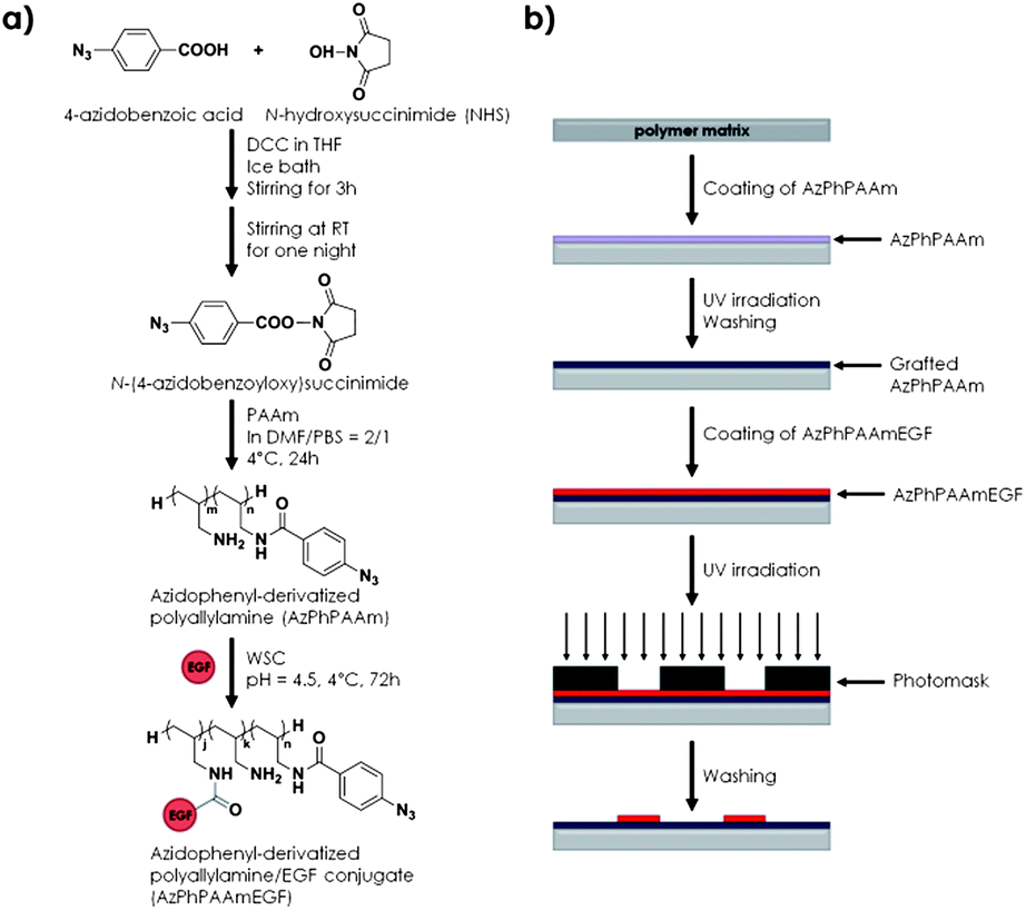 | ||
| Fig. 10 (a) Synthetic scheme of photoreactive polyallylamine conjugated to EGF and (b) substrate preparation and GF patterning strategy on a polystyrene substrate. | ||
When Chinese hamster ovary cells overexpressing EGF receptors were cultured on the patterned substrate, cell adhesion was similar to that without immobilized EGFs. However, the intensity of immunofluorescently labeled phosphorylated tyrosine was visible only in cells adhered on EGF-immobilized areas. Patterned EGFs also induced cell proliferation in contrast to platforms in the absence of GF. This represented one of the first examples in which the EGF was immobilized on the surface of a polymeric matrix with an impact on the study of EGF signaling transduction and on the manipulation of cells using artificial substrates.
Another GF immobilization strategy requiring UV light or a pulsed infrared laser to enable immobilization was presented by the group of Shoichet.66 In this case, VEGF165 was randomly modified with 4-(4-N-maleimidophenyl) butyric acid hydrazide in the presence of EDC and coupled to agarose-thiol via a Michael addition reaction.66 Fluorescence visualization served the authors to quantify around 900 ng mL−1 of VEGF immobilized within the hydrogel while only 80 ng mL−1 was physically adsorbed. VEGFR2+ bran-derived endothelial (bEnd3) cells were used to assess the bioactivity of covalently bound GF in comparison to soluble VEGF in a similar concentration. In both cases, similar proliferation profiles were found indicating that the covalent VEGF remains active upon immobilization. More interestingly, gradients of immobilized VEGFs could be created within the hydrogel to analyze the guiding capacity of the GF to tubule-like formation mimicking an in vivo VEGF gradient regulated by interstitial flow. Gradients were created taking advantage of the photolabile coumarin-protected agarose-sulfide groups. Therefore, controlling the scanning number and scanning regions of a confocal laser, gradients were observed upon immobilization of the fluorescently labeled VEGF. Three gradients were created with variations of 2.48, 1.65 and 1.00 ng mL−1 per μm and after 3 days of culture cells were observed to have penetrated to a depth of more than 200 μm and to form tubule-like structures for gradients of 1.65 and 1.00 ng mL−1 per μm. However, cells cultured on the steeper gradient (i.e. 2.48 ng mL−1) showed no evidence of tubular formation in the gel. The authors attributed this effect to saturation of VEGFR2 receptors limiting the cells to sense the gradient. In fact, the authors argued that as important as the gradient steepness is the starting concentration of the GF enhancing or limiting tubule extension. VEGF was also successfully attached to resorbable PLLA and PCL surfaces through WSC as presented by Albertsson et al.67
Physical entrapment
Traditionally, polymeric matrices and scaffolds have been used to deliver GFs that were entrapped inside. In this manner, release is controlled by: (i) diffusion, (ii) swelling, (iii) erosion or (iv) external stimuli (Fig. 11).4 Either way, control over release rate, orientation and effective dose is limited. These and new findings about the mechanisms that control GF delivery in organisms and successful efforts to reproduce those from a synthetic point of view have reduced interest for the delivery of physically entrapped GFs. However, several interesting examples have been found to date. For example Mooney and co-workers designed a system in which VEGF delivery is based on the compressive stimulation of an alginate hydrogel.68 Without mechanical stimulation, the release rate appeared to be constant (due to other modes presented in Fig. 11) and the cumulative release was increasing linearly with time. When mechanical stimuli were applied, the release rate increased five times compared to the control and depending on mechanical input the cumulative release could be up to double compared to the one for the control without mechanical stimuli. Alginate hydrogels both loaded and unloaded with VEGFs were implanted in vivo into the dorsal region of mice. | ||
| Fig. 11 Release modes of entrapped drugs in matrices or scaffolds. | ||
While no vascularization was observed without VEGFs either with or without mechanical stimuli, the neighbouring tissue of the implants showed enhanced vascularization for hydrogels loaded with VEGFs. Nevertheless, mechanically stimulated hydrogels showed a significant increase in vascularization compared to non-stimulated gels.
The group of Picart is actively involved in the presentation of diffusive BMP-2 from different material supports coated with polyelectrolyte matrices.69 Their strategy consists of the layer-by-layer (LbL) deposition of poly(L-lysine) (PLL) and hyaluronic acid (HA). After covalently cross-linking the films using EDC chemistry, these films were soaked in acidic solutions of BMP-2 to load the films with GF (Fig. 12).69b After GF loading for 1 h under optimized conditions, the local concentration of BMP-2 could be increased up to 500-fold in comparison to the concentration of the loading solution and it was dependent both on the deposition conditions and the film thickness.69b The thickness of the polyelectrolyte layers was also shown to have an effect on the diffusion of the GF. While 12 bilayers allowed diffusion, BMP-2 entrapped within 24 bilayer matrices showed a limited capability to diffuse.69b Release was demonstrated to follow an initial burst for the first 5 h while reaching a steady state which prolonged further release for several days.69b Additionally, the authors suggested a non-covalent interaction between BMP-2 and HA gels that could be used to tune the release properties.69b Finally, they tested this material for the culture of C2C12 myoblast cells. When C2C12 were seeded on films without BMP-2 normal differentiation into myotubes was observed.69b However, when cells were seeded on loaded films a higher activity of ALP was observed as an indication of osteogenic differentiation while troponin T expression (a marker of myogenic differentiation) decreased in a dose-dependent manner.69a Interestingly, those films could be used for three consecutive culture sequences while BMP-2 remained bioactive, which confirms the protective role of the polyelectrolyte films. These initial findings spurred the interest of the group to apply these layers, for example, as a coating of macroporous tricalcium phosphate (TCP)/hydroxyapatite (HAP) ceramic scaffolds.69c This resulted in significant amounts of BMP-2 loaded within the materials with controlled release properties compared to bare scaffolds and enhanced osteogenic differentiation remaining bioactive for long periods of time.69c As mentioned before, the stiffness of the films can be modulated by tuning the cross-linking via WSC (Fig. 12). Using this property, Picart showed that large differences in cell adhesion, spreading and mobility were found between the presentation of bound and soluble BMP-2 depending on the material stiffness.69b For example, no difference in cell spreading and adhesion was observed for cells cultured on stiff films both with bound BMP-2 or BMP-2 delivered in a soluble format. In contrast, when cells were seeded on soft films a significant increase in cell number, area and spreading velocity was observed in the case in which BMP-2 was loaded in the polyelectrolyte matrix, whereas no difference was found between BMP-2 delivered in solution or in the absence of BMP-2. As depicted in Fig. 12, the authors hypothesized that there must be a cooperation between BMP receptors and adhesion receptors when BMP receptors interact with highly localized BMP-2, which might affect cell shape and cytoskeletal dynamics in cases in which cell adhesion is initially poor (i.e. non-functionalized soft films). In contrast, when BMP-2 is presented in solution, BMP receptors diffuse for the complexation with soluble BMP-2 reducing the cross-talk with adhesion receptors.
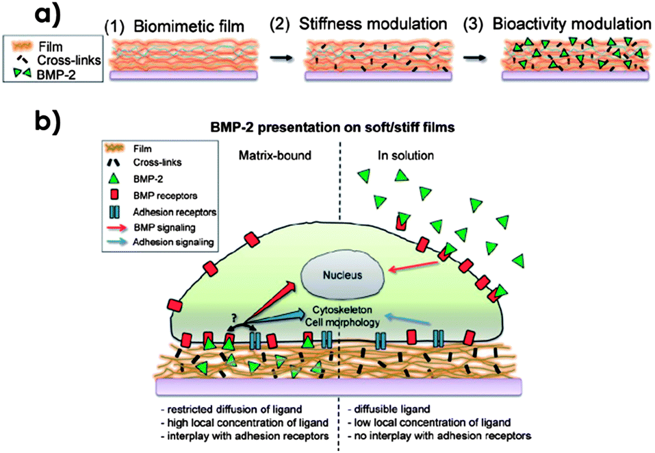 | ||
| Fig. 12 (a) Stiffness control and functionalization of polyelectrolyte LbL-deposited films with BMP-2. The film is formed by alternating the deposition of PLL and HA (1). EDC concentration and WSC reaction time can be used to tune the stiffness of the films (2). Incubation with BMP-2 is used to trap the GF within the film matrix (3). (b) Differences between the deliveries of soluble or matrix-bound BMP-2. While the crosstalk between BMP and adhesion receptors is allowed when BMP-2 is retained by the matrix thus creating a high local concentration of BMP receptors complexed to the GF in the vicinities of adhesion receptors, when BMP-2 is presented in solution, receptor diffusion to interact with soluble factors decreases this cross-talk.69b Copyright © 2011 Wiley-VCH Verlag GmbH & Co. KGaA, Weinheim. | ||
BMP-2 was also delivered within a nanostructure made of high-purity carbon fiber web (TCFW) in an approach presented by Saito et al.70 TCFWs with a diameter of 250 or 1000 nm were obtained by electrospinning polymer solutions showing good mechanical properties to function as implants. The scaffolds could entrap BMP-2 resulting in induction of ectopic new bone formation in vivo and they could repair large bone defects orthotopically.
Another interesting way to present GFs is by entrapping them in cubic inclusion bodies such as polyhedra. Inclusion bodies are proteinous crystals found for example in Bombyx mori cytoplasmatic polyhedrosis virus (BmCPV).71 Hiraki et al. have presented the co-expression of the FGF-2 encoding a sequence fused to the one for the virion outer capsid protein VP3 of the BmCPV gene together with the BmCPV polyhedron yielding around 10 μm large polyhedra containing FGF-2. The advantage of these protein crystals is that while they are stable and insoluble at physiological pH, the release is triggered at high pH. That was demonstrated by observing FGF-2 released in cell culture medium containing 5% FBS while no release was observed in PBS. Mouse chondrogenic cells and fibroblasts were cultured in the presence of FGF-2 polyhedra resulting in a higher proliferation when compared with normal polyhedra, which was proven to be regulated by the FGF receptors. The FGF-2 polyhedra were also shown to inhibit chondrogenic differentiation of ATDC5 as expected resulting in micron sized bioactive substances.
Recently, Park et al. presented an example of a potential multiple GF delivery system.72 Their approach consisted of constructing a matrix of PLGA microspheres coated with nanospheres of the same material via electrostatic interactions. Using preloaded nanospheres with dexamethasone (DEX), negatively charged GFs (i.e. BMP-7, IGF/FGF-2 and TGF-β3) were complexed with positively charged heparin, which allowed coating the nanospheres. By embedding hMSCs onto the nanosphere coated microspheres containing the various GFs, osteogenic, adipogenic and chondrogenic differentiation were observed.72 After four weeks of culturing hMSCs embedded onto the nanospheres, the expression levels of GAG, ALP and Oil red O were evaluated for the determination of their differentiation.72 These results demonstrated the specificity of each coated GF towards each kind of differentiation compared to a control in which hMSCs were cultured on bare nanospheres or nanospheres loaded with the complementary GFs.72 In addition, results obtained via reverse transcription polymerase chain reaction (RT-PCR) and Western blot of different genes related to the various differentiation pathways as well as histology and immunohistochemistry were in agreement.72 Finally, the transplantation of the scaffolds in vivo into mice showed that the factors remained in the scaffold matrix for up to 3 weeks, thereby enabling prolonged stimulation of the differentiation of the embedded hMSCs.72
Conclusions
To date, a variety and number of methodologies to present GFs with different materials have shown enormous growth. Most of the strategies presented in this discussion demonstrated enhanced stability of the GFs upon immobilization. Enhanced performances in vitro and in vivo were observed in the case of immobilized GFs when compared to traditional regenerative medicine treatments employing soluble GFs. In addition, a common feature found in all presented strategies is the creation of high local concentrations of GFs which favour (i) the formation of complexes with specific cell receptors in order to initiate a cascade of reactions, regulating the signal transduction to coordinate cell processes such as tissue formation, maintenance or regeneration73 and (ii) multivalent complexes and hampered internalization, thus resulting in special mitogenic effects.74 However, even though benefits have been found in systems with immobilized GFs over soluble GFs, to achieve prolonged doses in terms of regenerative properties, there is still a need for controlling the spatiotemporal presence of GFs at or near the targeted site to allow e.g. continuous remodeling.This spatiotemporal control is endogenously found in living organisms based on interactions found in the microenvironment by elements in the ECM.75 Notwithstanding that some aspects of these natural concepts to deliver GFs can be recognized in reports as discussed in this feature article, it is evident that issues such as interaction affinity, GF stability, orientation and release rates are known to be far from optimal and difficult to predict in vivo. Some of these aspects have recently been reported through adopting supramolecular chemistry to dynamically present peptides and proteins at surfaces.76,77 Further progress in this field can only take place if chemical and biological disciplines join forces both to elucidate living biological systems and to reproduce them from a chemical synthetic perspective while incorporating the required natural characteristics for an improved tissue regeneration performance when using GFs.78
Notes and references
-
(a) P. Tayalia and D. J. Mooney, Adv. Mater., 2009, 21, 3269 CrossRef CAS PubMed
; (b) F.-M. Chen, M. Zhang and Z.-F. Wu, Biomaterials, 2010, 31, 6279 CrossRef CAS PubMed
-
(a) F. Rosso, A. Giordano, M. Barbarisi and A. Barbarisi, J. Cell. Physiol., 2004, 199, 174 CrossRef CAS PubMed
- E. Frieden, J. Chem. Educ., 1975, 52, 754 CrossRef CAS PubMed
- N. X. Wang and H. A. von Recum, Macromol. Biosci., 2011, 11, 321 CrossRef CAS PubMed
- P. Jonkheijm, D. Weinrich, H. Schröder, C. M. Niemeyer and H. Waldmann, Angew. Chem., Int. Ed., 2008, 47, 9618 CrossRef CAS PubMed
-
(a) M. J. W. Ludden, D. N. Reinhoudt and J. Huskens, Chem. Soc. Rev., 2006, 35, 1122 RSC
-
(a) K. Kato, H. Sato and H. Iwata, Langmuir, 2005, 21, 7071 CrossRef CAS PubMed
- J.-M. Nam, P. M. Nair, R. M. Neve, J. W. Gray and J. T. Groves, ChemBioChem, 2006, 7, 436 CrossRef CAS PubMed
- H. Lee, T. H. Kim and T. G. Park, J. Controlled Release, 2002, 83, 109 CrossRef CAS PubMed
- S. Y. Yoo, A. Merzlyak and S.-W. Lee, Soft Matter, 2011, 7, 1660 RSC
- R. G. Wylie, S. Ahsan, Y. Aizawa, K. L. Maxwell, C. M. Morshead and M. S. Shoichet, Nat. Mater., 2011, 10, 799 CrossRef CAS PubMed
-
(a) H. Cui, M. J. Webber and S. I. Stupp, Pept. Sci., 2010, 94, 1 CrossRef CAS PubMed
- J. B. Matson, R. H. Zha and S. I. Stupp, Curr. Opin. Solid State Mater. Sci., 2011, 15, 225 CrossRef CAS PubMed
-
(a) R. N. Shah, N. A. Shah, M. M. Del Rosario Lim, C. Hsieh, G. Nuber and S. I. Stupp, Proc. Natl. Acad. Sci. U. S. A., 2010, 107, 3293 CrossRef CAS PubMed
-
(a) P. C. H. Hsieh, M. E. Davis, J. Gannon, C. MacGillivray and R. T. Lee, J. Clin. Invest., 2006, 116, 237 CrossRef CAS PubMed
- M. E. Davis, P. C. H. Hsieh, T. Takahashi, Q. Song, S. Zhang, R. D. Kamm, A. J. Grodzinsky, P. Anversa and R. T. Lee, Proc. Natl. Acad. Sci. U. S. A., 2006, 103, 8155 CrossRef CAS PubMed
- J. Cabanas-Danés, C. Nicosia, E. Landman, M. Karperien, J. Huskens and P. Jonkheijm, J. Mater. Chem. B, 2013, 1, 1903 RSC
- L. Li, J. R. Klim, R. Derda, A. H. Courtney and L. L. Kiessling, Proc. Natl. Acad. Sci. U. S. A., 2011, 108, 11745 CrossRef CAS PubMed
-
(a) R. E. Hileman, J. R. Fromm, J. M. Weiler and R. J. Linhardt, BioEssays, 1998, 20, 156 CrossRef CAS PubMed
- S. Ashikari-Hada, H. Habuchi, Y. Kariya, N. Itoh, A. H. Reddi and K. Kimata, J. Biol. Chem., 2004, 279, 12346 CrossRef CAS PubMed
- L. D. Thompson, M. W. Pantoliano and B. A. Springer, Biochemistry, 1994, 33, 3831 CrossRef CAS PubMed
- M. Fannon, K. E. Forsten and M. A. Nugent, Biochemistry, 2000, 39, 1434 CrossRef CAS PubMed
- J. Schlessinger, A. N. Plotnikov, O. A. Ibrahimi, A. V. Eliseenkova, B. K. Yeh, A. Yayon, R. J. Linhardt and M. Mohammadi, Mol. Cell, 2000, 6, 743 CrossRef CAS PubMed
- L. Pellegrini, D. F. Burke, F. von Delft, B. Mulloy and T. L. Blundell, Nature, 2000, 407, 1029 CrossRef CAS PubMed
- D. S. W. Benoit and K. S. Anseth, Acta Biomater., 2005, 1, 461 CrossRef PubMed
- D. S. W. Benoit, A. R. Durney and K. S. Anseth, Biomaterials, 2007, 28, 66 CrossRef CAS PubMed
- D. B. Pike, S. Cai, K. R. Pomraning, M. A. Firpo, R. J. Fisher, X. Z. Shu, G. D. Prestwich and R. A. Peattie, Biomaterials, 2006, 27, 5242 CrossRef CAS PubMed
- S. E. Kim, S.-H. Song, Y. P. Yun, B.-J. Choi, I. K. Kwon, M. S. Bae, H.-J. Moon and Y.-D. Kwon, Biomaterials, 2011, 32, 366 CrossRef CAS PubMed
-
(a) C. Wolf-Brandstetter, A. Lode, T. Hanke, D. Scharnweber and H. Worch, J. Biomed. Mater. Res., Part A, 2006, 79, 882 CrossRef PubMed
- M. Tanihara, Y. Suzuki, E. Yamamoto, A. Noguchi and Y. Mizushima, J. Biomed. Mater. Res., 2001, 56, 216 CrossRef CAS PubMed
- J. J. Yoon, H. J. Chung, H. J. Lee and T. G. Park, J. Biomed. Mater. Res., Part A, 2006, 79, 934 CrossRef PubMed
- M. A. Princz and H. Sheardown, J. Biomat. Sci., Pol. Ed., 2008, 19, 1201 CrossRef CAS PubMed
- J. Lee, J. J. Yoo, A. Atala and S. J. Lee, Biomaterials, 2012, 33, 6709 CrossRef CAS PubMed
- J. S. Lee, D. H. Go, J. W. Bae, S. J. Lee and K. D. Park, J. Controlled Release, 2007, 117, 204 CrossRef CAS PubMed
- S. E. Sakiyama-Elbert and J. A. Hubbell, J. Controlled Release, 2000, 65, 389 CrossRef CAS PubMed
- S. E. Sakiyama-Elbert and J. A. Hubbell, J. Controlled Release, 2000, 69, 149 CrossRef CAS PubMed
- M. K. Lee and A. D. Lander, Proc. Natl. Acad. Sci. U. S. A., 1991, 88, 2768 CrossRef CAS
- A. Herland, K. M. Persson, V. Lundin, M. Fahlman, M. Berggren, E. W. H. Jager and A. I. Teixeira, Angew. Chem., Int. Ed., 2011, 50, 12529 CrossRef CAS PubMed
-
(a) K. Rajangam, H. A. Behanna, M. J. Hui, X. Han, J. F. Hulvat, J. W. Lomasney and S. I. Stupp, Nano Lett., 2006, 6, 2086 CrossRef CAS PubMed
-
(a) R. M. Capito, H. S. Azevedo, Y. S. Velichko, A. Mata and S. I. Stupp, Science, 2008, 319, 1812 CrossRef CAS PubMed
- R. Mammadov, B. Mammadov, S. Toksoz, B. Aydin, R. Yagci, A. B. Tekinay and M. O. Guler, Biomacromolecules, 2011, 12, 3508 CrossRef CAS PubMed
-
(a) R. Mammadov, B. Mammadov, M. O. Guler and A. B. Tekinay, Biomacromolecules, 2012, 13, 3311 CrossRef CAS PubMed
-
(a) I. Freeman, A. Kedem and S. Cohen, Biomaterials, 2008, 29, 3260 CrossRef CAS PubMed
- C. M. Kolodziej, S. H. Kim, R. M. Broyer, S. S. Saxer, C. G. Decker and H. D. Maynard, J. Am. Chem. Soc., 2012, 134, 247 CrossRef CAS PubMed
- X. Deng and J. Lahann, Macromol. Rapid Commun., 2012, 33, 1459 CrossRef CAS PubMed
- S. M. Anderson, T. T. Chen, M. L. Iruela-Arispe and T. Segura, Biomaterials, 2009, 30, 4618 CrossRef CAS PubMed
-
(a) N. Yamaguchi, L. Zhang, B.-S. Chae, C. S. Palla, E. M. Furst and K. L. Kiick, J. Am. Chem. Soc., 2007, 129, 3040 CrossRef CAS PubMed
- K. L. Kiick, Soft Matter, 2008, 4, 29 RSC
- S. H. Kim and K. L. Kiick, Peptides, 2007, 28, 2125 CrossRef CAS PubMed
- P. R. Kuhl and L. G. Griffith-Cima, Nat. Med., 1996, 2, 1022 CrossRef CAS PubMed
- V. H. Fan, A. Au, K. Tamama, R. Littrell, L. B. Richardson, J. W. Wright, A. Wells and L. G. Griffith, Stem Cells, 2007, 25, 1241 CrossRef CAS PubMed
- S. Wu, A. Wells, L. G. Griffith and D. A. Lauffenburger, Biomaterials, 2011, 32, 7524 CrossRef CAS PubMed
- N. A. Marcantonio, C. A. Boehm, R. J. Rozic, A. Au, A. Wells, G. F. Muschler and L. G. Griffith, Biomaterials, 2009, 30, 4629 CrossRef CAS PubMed
- J. Ichinose, M. Morimatsu, T. Yanagida and Y. Sako, Biomaterials, 2006, 27, 3343 CrossRef CAS PubMed
- T. L. M. Pohl, J. H. Boergermann, G. K. Schwaerzer, P. Knaus and E. A. Cavalcanti-Adam, Acta Biomater., 2012, 8, 772 CrossRef CAS PubMed
-
(a) K. Alberti, R. E. Davey, K. Onishi, S. George, K. Salchert, F. P. Seib, M. Bornhauser, T. Pompe, A. Nagy, C. Werner and P. W. Zandstra, Nat. Methods, 2008, 5, 645 CrossRef CAS PubMed
- L. . L. Y. Chiu, R. D. Weisel, R.-K. Li and M. Radisic, J. Tissue Eng. Regener. Med., 2011, 5, 69 CrossRef CAS PubMed
- Y. Miyagi, L. L. Y. Chiu, M. Cimini, R. D. Weisel, M. Radisic and R.-K. Li, Biomaterials, 2011, 32, 1280 CrossRef CAS PubMed
- Y. M. Shin, Y. B. Lee, S. J. Kim, J. K. Kang, J.-C. Park, W. Jang and H. Shin, Biomacromolecules, 2012, 13, 2020 CrossRef CAS PubMed
- Y. B. Lee, Y. M. Shin, J. H. Lee, I. Jun, J. K. Kang, J.-C. Park and H. Shin, Biomaterials, 2012, 33, 8343 CrossRef CAS PubMed
- H. Lee, S. M. Dellatore, W. M. Miller and P. B. Messersmith, Science, 2007, 318, 426 CrossRef CAS PubMed
- B. J. Klenkler, M. Griffith, C. Becerril, J. A. West-Mays and H. Sheardown, Biomaterials, 2005, 26, 7286 CrossRef CAS PubMed
-
(a) B. K. Mann, R. H. Schmedlen and J. L. West, Biomaterials, 2001, 22, 439 CrossRef CAS PubMed
- P.-R. Chen, M.-H. Chen, F.-H. Lin and W.-Y. Su, Biomaterials, 2005, 26, 6579 CrossRef CAS PubMed
- Y. Ito, G. Chen and Y. Imanishi, Bioconjugate Chem., 1998, 9, 277 CrossRef CAS PubMed
- Y. Aizawa, R. Wylie and M. Shoichet, Adv. Mater., 2010, 22, 4831 CrossRef CAS PubMed
- U. Edlund, T. Sauter and A. C. Albertsson, Polym. Adv. Technol., 2011, 22, 166 CrossRef CAS
- K. Y. Lee, M. C. Peters, K. W. Anderson and D. J. Mooney, Nature, 2000, 408, 998 CrossRef CAS PubMed
-
(a) T. Crouzier, K. Ren, C. Nicolas, C. Roy and C. Picart, Small, 2009, 5, 598 CrossRef CAS PubMed
- K. Aoki, Y. Usui, N. Narita, N. Ogiwara, N. Iashigaki, K. Nakamura, H. Kato, K. Sano, N. Ogiwara, K. Kametani, C. Kim, S. Taruta, Y. A. Kim, M. Endo and N. Saito, Small, 2009, 5, 1540 CrossRef CAS PubMed
- H. Mori, C. Shukunami, A. Furuyama, H. Notsu, Y. Nishizaki and Y. Hiraki, J. Biol. Chem., 2007, 282, 17289 CrossRef CAS PubMed
- J. S. Park, H. N. Yang, D. G. Woo, S. Y. Jeon and K.-H. Park, Biomaterials, 2011, 32, 28 CrossRef CAS PubMed
- M. P. Lutolf and J. A. Hubbell, Nat. Biotechnol., 2005, 23, 47 CrossRef CAS PubMed
- Y. Ito, Soft Matter, 2008, 4, 46 RSC
- R. O. Hynes, Science, 2009, 326, 1216 CrossRef CAS PubMed
- G. A. Hudalla and W. L. Murphy, Soft Matter, 2011, 7, 9561 RSC
-
(a) Q. An, J. Brinkmann, J. Huskens, S. Krabbenborg, J. de Boer and P. Jonkheijm, Angew. Chem., Int. Ed., 2012, 51, 12233 CrossRef CAS PubMed
- P. M. Mendes, Chem. Soc. Rev., 2008, 37, 2512 RSC
| This journal is © The Royal Society of Chemistry 2014 |