 Open Access Article
Creative Commons Attribution 3.0 Unported Licence
Long term stability of air processed inkjet infiltrated carbon-based printed perovskite solar cells under intense ultra-violet light soaking†
Syed Ghufran
Hashmi
 *a,
Armi
Tiihonen
a,
David
Martineau
b,
Merve
Ozkan
c,
Paola
Vivo
d,
Kimmo
Kaunisto
e,
Vainio
Ulla
a,
Shaik Mohammed
Zakeeruddin
f and
Michael
Grätzel
f
aNew Energy Technologies Group, Department of Applied Physics, Aalto University, P. O. BOX 15100 Aalto, FI-00076, Espoo, Finland. E-mail: ghufran.hashmi@aalto.fi
bSolaronix SA, Rue de l' Ouriette 129, CH-1170 Aubonne, Switzerland
cDepartment of Forest Products Technology Aalto University School of Chemical Technology, Espoo, Finland
dDepartment of Chemistry and Bioengineering, Tampere University of Technology, Finland
eVTT Technical Research Center of Finland, P. O. Box 1000, FI-02150 Espoo, Finland
fLaboratory of Photonics and Interfaces, Ecole Polytechnique Federale de Lausanne (EPFL), CH G1 551, Station 6, CH-1015 Lausanne, Switzerland
First published on 10th February 2017
Abstract
The long term stability of air processed inkjet infiltrated carbon based perovskite solar cells (CPSCs) is investigated under intense ultra-violet light soaking equivalent to 1.5 Sun UV light illumination. Two batches of the fabricated CPSCs were exposed systematically i.e. first without implementing any protective coating and then epoxying the CPSCs through a low cost commonly available epoxy which was applied to serve as a barrier against moisture and humidity intrusion. The CPSCs with no protective layer against moisture and humidity exhibited impressive preliminary stability for hundreds of hours during their exposure to intense UV light and provided great motivation to test the CPSCs further with more optimization. As a result, the CPSCs having commonly available epoxy as a protective barrier exhibited remarkable durability and showed no performance degradation for a period of 1002 hours under intense and continuous 1.5 Sun equivalent UV light illumination proving that the technology is clearly not inherently unstable and that future developments might lead to market breakthroughs.
Perovskite solar cells (PSCs), as next generation photovoltaic devices, have recently shown tremendous potential by competing with existing PV technologies due to a rapid increase in their solar to electrical conversion efficiencies now exceeding 22% and 12% for laboratory sized devices and large area modules respectively.1,2 Despite exhibiting higher efficiencies, the biggest challenge associated with the traditional geometry of PSCs3–5 is the lack of long term device stability.6–11 The main cause reported for their degradation is the solubility of the perovskite light absorbing layer in many solvents including water except a few unipolar ones rendering the cell operation in the traditional geometry highly sensitive to moisture intrusion and humidity.6,7 Therefore several types of new materials, strategies and device geometries have been introduced to address the aforementioned issues.8,12–16 As a result of these contributions, one class of PSCs i.e. carbon back contact based printable perovskite solar cells (CPSCs)16–19 have emerged as a potential candidate which may be produced at low cost due to several factors. For instance the incorporated materials used in this device structure (i.e. TiO2, ZrO2 and carbon nanoparticles) are abundantly available and can be transformed into screen printable pastes and can also be easily stacked through established printing techniques such as screen printing.16–19 Additionally, these CPSCs do not utilize the traditional costly hole transporting material (HTM) i.e. spiro-OMeTAD that, along with its additives, has also been identified as a major source of performance degradation during long term stability tests in traditional PSCs.7,20 Moreover, the up-scaling of CPSCs may be realized when some of their traditional fabrication steps such as manual infiltration of the perovskite precursor solution could be replaced with established automated processes such as inkjet printing which is suitable for large area module manufacturing.
Keeping this fact as the motivation, we recently reported for these CPSCs a successful demonstration of the automated infiltration of the perovskite precursor ink through a material inkjet printer21 and observed their very high long term stability for more than 1000 hours under continuous light illumination equivalent to 1 Sun at 35 °C without any encapsulation.21 These promising stability results encouraged us to investigate further the stability of these air processed inkjet infiltrated CPSCs under a new stress i.e. ultra-violet (UV) light which has been identified as one of the key issues for the long term stability of other types of PV systems such as dye-sensitized solar cells (DSSCs),22,23 and has raised concerns also in the field of perovskite solar cells.8,24,25
Hence one batch of inkjet infiltrated CPSCs (similar to the cells fabricated in ref. 20) with no encapsulation was initially placed under intense 1.5 Sun UV light illumination in an electronic weather chamber under open circuit conditions with approximately 45% relative air controlled humidity and 40 °C temperature of the cells (see details in the ESI†). These test conditions are harsh: already 302 hours of test results in the same total UV irradiation than the standard durability tests of thin-film terrestrial solar cells aim for.24
Fig. 1 shows the average long term photovoltaic performance of this batch (5 cells) for a period of 751 hours along with their standard deviations whereas the photovoltaic performance of the individual devices is summarized in Table S1 (ESI†). The subjected CPSCs exhibited highly stable performance in the first 250 hours under UV illumination and an increase in mean JSC (17%) and efficiency (8.6%) was observed (Fig. 1 and Table S1, ESI†). We strongly believe that these initial enhancements in the JSC and the efficiency resulted from additional curing of the perovskite crystals in the UV light after the initial heating step of the perovskite precursor ink which was executed to transform the liquid ink into crystals of the perovskite light absorbing layer and its curing for 1 hour (see ESI†). The initial short term stability (for the first 250 hours) of this batch of CPSCs also suggested that despite the high porosity, the thick carbon (12–14 μm) and then thinner ZrO2 (1–2 μm) were remarkably able to protect the perovskite light absorbing layer against the maintained humidity and UV illumination in the electronic aging chamber without any encapsulation.
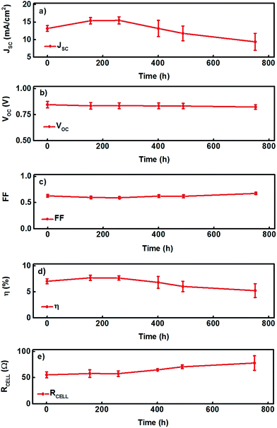 | ||
| Fig. 1 (a–e) Stability data of a batch (batch 1) of PSCs (5 cells) along with their standard deviations with no epoxy for a period of 751 hours. | ||
Nevertheless over a longer period of time, the signs of degradation in the CPSCs of this batch appeared: parts of the dark-brown colored perovskite layer (in fresh CPSCs, Fig. 2a and b) slowly changed to yellow following 751 hours of aging (Fig. 2c and d) which can be correlated with the disappearance of HI and CH3NH2 and formation of lead iodide (PbI2) as indicated elsewhere.6,26,27 This transformation into PbI2 was also observed around the edges of carbon electrodes in our first report regarding the inkjet infiltration of perovskite precursor ink into these CPSCs and was also confirmed through XRD analysis.21 As a result, both the initial average JSC and power conversion efficiency (PCE) were reduced by ∼25% and 28%, respectively, due to the performance degradation in the individual cells of this batch (Fig. 1a–e, Table S1-ESI†). Fig. 3 shows the J–V curve of the degraded CPSC shown in Fig. 2. Nevertheless, the VOC only decreases marginally by 2.7% and the FF of the fabricated devices even improved compensating for the decrease in JSC, attesting to the strong stability of the carbon layer as the back contact of the CPSCs and reveals that the durability of these CPSCs may be improved if the perovskite light absorbing layer could be additionally protected from moisture penetration.
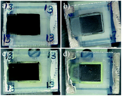 | ||
| Fig. 2 (a and b) Front and back views of a CPSC (coded P13) before UV aging; (c and d) front and back views of the same CPSC after UV aging for 751 hours. | ||
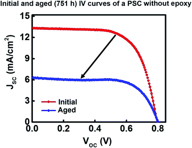 | ||
| Fig. 3 Initial and aged (for 751 h) I–V curves of the degraded CPSC (coded P13, see Table S1, ESI†) shown in Fig. 2. | ||
The device geometry of these CPSCs allows great freedom for selecting the sealing method. The durability of the protective carbon layer made it possible to simply apply commonly available slow drying viscous epoxy as the sealant of the cells. The epoxy does not penetrate into the pores of the printed carbon electrode nor into the photo-active area and provides an opportunity to easily block the pores of the non-active areas of the device. Therefore one more batch (batch 2) consisting of 7 CPSCs was subjected again in the aforementioned electronic weather chamber to heavy UV light illumination; this time the active and non-active porous areas of each cell were protected with the slow drying epoxy as shown in Fig. 4a and b (see ESI†).
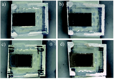 | ||
| Fig. 4 (a and b) Front and back views of a CPSC (coded P12) covered with epoxy before UV aging; (c and d) front and back views of the same CPSC after UV aging for 1002 hours. | ||
Fig. 5a–e depict the average photovoltaic performance of 7 CPSCs of batch 2 along with their standard deviations whereas Table S2† lists the photovoltaic performance of the individual devices (see ESI†). As expected, the overall photovoltaic performance of this batch was remarkably improved during the long term stability test which was conducted over a longer period of 1002 h (Fig. 5a–e, Table S2†). The average JSC and efficiency of this batch were retained at the initial level during the aging hours. Although signs of degradation appeared again at the edges of the devices (Fig. 4c and d) – possibly as a result of incomplete covering of the edge areas of the cells by the protective layers – the data presented in Fig. 5(a–e) endorse that these changes did not affect the efficiency of the cells during the aging test. In comparison with the first cell batch, the degradation rate was significantly suppressed after applying the epoxy as a barrier to moisture and humidity. Fig. 6 shows the initial and final (after 1002 hours of UV aging) J–V curves of a stable CPSC sealed with epoxy from batch 2 that is depicted in Fig. 4. A similar enhancement in the photovoltaic performance is also observed in our earlier report where the devices were kept in a vacuum for 3 weeks (ref. 21) which suggests that further performance enhancements in the fabricated devices are possible if the moisture and air intrusion could be blocked. We believe that this is an important finding since the epoxy can also be potentially applied in a more professional manner through established printing techniques such as screen printing. Thus it can also be integrated as a fabrication step in the realization of fully printed CPSCs.
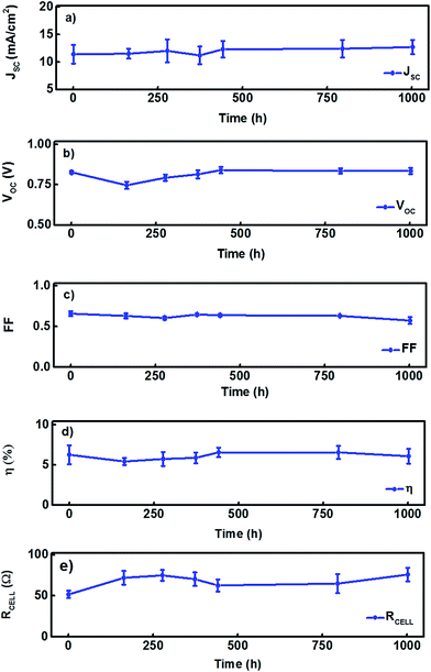 | ||
| Fig. 5 (a–e) Stability data of a batch of PSCs (7 cells) along with their standard deviations with epoxy for a period of 1002 hours. | ||
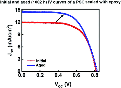 | ||
| Fig. 6 Initial and aged (for 1002 h) J–V curves of the stable PSC (coded P12) shown in Fig. 4(a and d). | ||
Additionally the changes in the appearance of the active areas of the cells were quantitatively analyzed by using a camera imaging technique as demonstrated in our earlier report for CPSCs21 (see ESI†). Fig. 7 illustrates the appearance of a yellow color (with the decrease of the blue pixel value and increase in other pixel values) on the interior of the active area of the cells in batch 1 during the aging test. PbI2 is yellow in color, so it seems that the cells in batch 1 are losing perovskite not only from the edges of the cells, which is visible to the eye from Fig. 2c and d but also from the central areas of the cells (Fig. 2c). On the other hand, the only change in color for the epoxy-protected CPSCs of batch 2 has been observed at the very edges of the cells (Fig. 4c). This did not penetrate towards the active area of the CPSCs (Fig. 4c and d). This suggests that there were no chemical changes that could significantly affect the color of the perovskite light absorbing layer and consequently supports the reason for the high stability in the photovoltaic performance of the fabricated devices.
Furthermore, the structural stability of the fabricated CPSCs for both batches was also cross-checked by performing micro-area mapping through an XRD technique which is summarized in Fig. 8 with the patterns of perovskite (COD 4335634),28 lead iodide (ICSD 68819),3,29 and graphite (COD 9011577, contained in the carbon paste used in the cells).30 Initially, PbI2 was not visible in the cells with or without epoxy sealing. In accordance with the camera imaging analysis, clear PbI2 peaks appear in the aged cell of batch 1 whereas the cell from batch 2 shows no marks of PbI2 even after the aging test (Fig. 8). The clear degradation in the CPSCs also suppresses the perovskite peaks of the sample of batch 1. Additionally, no significant differences between the spectra of fresh and aged cells of batch 2 were observed which indicates that the epoxy-protected cells have indeed been structurally stable during the aging.
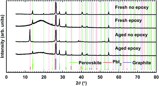 | ||
| Fig. 8 XRD results for the central active area of one fresh and one aged sample cell with and without epoxy sealing, accompanied by the phase patterns of perovskite, lead iodide, and graphite. The largest peak (26.4°) is cut here. The full data are presented in the ESI.† | ||
To further support the aforementioned interpretations, time-resolved photoluminescence (PL) studies (see ESI† for details) were also carried out in order to investigate the efficiency of charge injection and collection, and the transport efficiency between the interfaces of the cells. PL decay graphs, for the peak maximum of 770 nm upon laser pulse excitation around 650 nm, of representative samples from batch 1 and batch 2 are shown in Fig. 9. The pre-exponential amplitudes and PL lifetimes of the 2- or 3-exponential fit components are presented in Table 1. The average PL lifetimes of batch 1 and 2 are 21.6 ns and 4.1 ns, respectively. This means that the epoxified samples of batch 2 are more likely to accelerate light-induced charge separation, thus restricting carrier recombination,31 which correlates well with the results of the aging test. The contribution of the long-lived states of batch 2 is only 9% in total, showing their minor contribution with respect to that of the fast components (91%, <0.2 ns). The samples of batch 1 do not show a fast amplitude at all. These results are in good agreement with the findings of a previous study,31 where the authors demonstrate that the PL of PSCs encapsulated with PDMS is quenched to a greater degree than in unencapsulated devices.
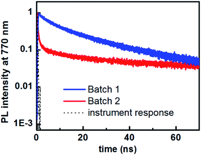 | ||
| Fig. 9 Normalized PL decays of aged samples belonging to batch 1 and batch 2, together with the instrument response function (lamp). | ||
| Batch | a 1 | τ 1 (ns) | a 2 | τ 2 (ns) | a 3 | τ 3 (ns) | Average lifetime (ns) |
|---|---|---|---|---|---|---|---|
| Batch 1 | — | — | 0.80 | 11.7 ± 0.8 | 0.20 | 61.1 ± 3.7 | 21.6 ± 1.4 |
| Batch 2 | 0.91 | <0.2 | 0.06 | 9.1 ± 2.1 | 0.03 | 105.2 ± 15.1 | 4.1 ± 0.6 |
Hence all the aforementioned key observations suggest that the perovskite light absorbing layer can potentially exhibit long term stability in this interesting configuration of PSCs by utilizing very low cost and commonly available epoxies such as those used in this report which not only keep the active layer alive but also provide a possible additional barrier against the intrusion of moisture and humidity. Although the popular manual doctor-blade method was used for the deposition of the epoxy as a moisture barrier in this experiment, we also intend to apply the established screen printing technique as a material deposition method for such epoxy resins in our future work which has been realized as an effective method to achieve reproducible results and can be easily integrated for the realization of fully printed PSCs.21
In conclusion we successfully demonstrated again the very high stability of CPSCs (which are produced through non-vacuum based scalable processes such as screen printing or inkjet printing) in heavy ultra-violet light soaking. The CPSCs passing a 1000 hour aging test under visible illumination21 is already a good result. Here, we have shown the impressive durability of the same cell type during its exposure to extreme 1.5 Sun UV illumination for hundreds of hours without any sealing of the air atmosphere. Finally, we have demonstrated an even more remarkable pass of a 1002 hour test under the same 1.5 Sun UV illumination in air using only a simple epoxy glue sealing of the cells. The total amount of UV irradiation during the test actually even exceeds the targets for the commercial terrestrial thin-film cells.24 The results presented in this work are therefore very promising from the commercialization view point of perovskite solar cells – the technology is clearly not inherently unstable and future developments might lead to market breakthroughs.
Acknowledgements
This work was financed through grant number 287641. Ghufran Hashmi gratefully acknowledges the Academy of Finland for the post-doctoral research fellowship and also expresses special thanks to Solaronix for hosting his research mobility for the project “Cutting-Edge Third Generation Advanced Photovoltaic Devices”. A. T. and P. V. acknowledge the Academy of Finland (projects SOLID, 271081 and Hybrid Nano, 268672, respectively). M. G. thanks the Swiss National Science Foundation (SNSF) for financial support. M. O. acknowledges the PhD scholarship SELECT+ (Environomical pathways for sustainable energy services). The authors also thank Dr Hanna Hakola (Department of Chemistry and Bioengineering, Tampere University of Technology) and Dr Pasi Myllyperkiö (Nanoscience Center, University of Jyväskylä) for their help with the photoluminescence measurements. The provision of facilities and technical support by Aalto University at OtaNano – Nanomicroscopy Center (Aalto-NMC) is also acknowledged.References
- Best Research Cell-Efficiencies, National Renewable Energy Laboratory (NREL), April 20 2016, http://www.nrel.gov/ncpv/images/efficiency_chart.jpg.
- A. Agresti, S. Pescetelli, A. L. Palma, A. E. D. R. Castillo, D. Konios, G. Kakavelakis, S. Razza, L. Cinà, E. Kymakis, F. Bonaccorso and A. D. Carlo, ACS Energy Lett., 2017, 2, 279–287 CrossRef CAS.
- J. Burschka, N. Pellet, S. J. Moon, R. Humphry-Baker, P. Gao, M. K. Nazeeruddin and M. Grätzel, Nature, 2013, 499, 316–319 CrossRef CAS PubMed.
- H. Zhou, Q. Chen, G. Li, S. Luo, T. B. Song, H. S. Duan, Z. Hong, J. You, Y. Liu and Y. Yang, Science, 2014, 345, 542–546 CrossRef CAS PubMed.
- M. Liu, M. B. Johnston and H. J. Snaith, Nature, 2013, 501, 395–398 CrossRef CAS PubMed.
- D. Wang, M. Wright, N. K. Elumalai and A. Uddin, Sol. Energy Mater. Sol. Cells, 2016, 147, 255–275 CrossRef CAS.
- Y. Han, S. Meyer, Y. Dkhissi, K. Weber, J. M. Pringle, U. Bach, L. Spiccia and Y. B. Cheng, J. Mater. Chem. A, 2015, 3, 8139–8147 CAS.
- T. Leijtens, G. E. Eperon, S. Pathak, A. Abate, M. M. Lee and H. J. Snaith, Nat. Commun., 2013, 4(2885), 1–8 Search PubMed.
- B. Philippe, B. W. Park, R. Lindblad, J. Oscarsson, S. Ahmadi, E. M. J. Johansson and H. Rensmo, Chem. Mater., 2015, 27(5), 1720–1731 CrossRef CAS.
- B. Conings, J. Drijkoningen, N. Gauquelin, A. Babayigit, J. D'Haen, L. D'Olieslaeger, A. Ethirajan, J. Verbeeck, J. Manca, E. Mosconi, F. D. Angelis and H. G. Boyen, Adv. Energy Mater., 2015, 5, 1500477 CrossRef.
- W. Li, H. Dong, L. Wang, N. Li, X. Guo, J. Li and Y. Qiu, J. Mater. Chem. A, 2014, 2, 13587–13592 CAS.
- Q. Tai, P. You, H. Sang, Z. Liu, C. Hu, H. L. W. Chan and F. Yan, Nat. Commun., 2016, 7(11105), 1–8 Search PubMed.
- S. Guarnera, A. Abate, W. Zhang, J. M. Foster, G. Richardson, A. Petrozza and H. J. Snaith, J. Phys. Chem. Lett., 2015, 6, 432–437 CrossRef CAS PubMed.
- K. G. Lim, H. B. Kim, J. Jeong, H. Kim, J. Y. Kim and T. W. Lee, Adv. Mater., 2014, 26, 6461–6466 CrossRef CAS PubMed.
- Y. Bai, H. Yu, Z. Zhu, K. Jiang, T. Zhang, N. Zhao, S. Yang and H. Yan, J. Mater. Chem. A, 2015, 3, 9098–9102 CAS.
- A. Mei, X. Li, L. Liu, Z. Ku, T. Liu, Y. Rong, M. Xu, M. Hu, J. Chen, Y. Yang, M. Grätzel and H. Han, Science, 2014, 345, 295–298 CrossRef CAS PubMed.
- L. Liu, A. Mei, T. Liu, P. Jiang, Y. Sheng, L. Zhang and H. Han, J. Am. Chem. Soc., 2015, 137(5), 1790–1793 CrossRef CAS PubMed.
- J. Chen, Y. Rong, A. Mei, Y. Xiong, T. Liu, Y. Sheng, P. Jiang, L. Hong, Y. Guan, X. Zhu, X. Hou, M. Duan, J. Zhao, X. Li and H. Han, Adv. Energy Mater., 2015, 6, 1502009 CrossRef.
- Z. Ku, Y. Rong, M. Xu, T. Liu and H. Han, Sci. Rep., 2013, 3(3132), 1–5 Search PubMed.
- J. Yang, B. D. Siempelkamp, D. Liu and T. L. Kelly, ACS Nano, 2015, 9, 1955–1963 CrossRef CAS PubMed.
- S. G. Hashmi, D. Martineau, X. Li, M. Ozkan, A. Tiihonen, M. I. Dar, T. Sarikka, S. M. Zakeeruddin, J. Paltakari, P. D. Lund and M. Grätzel, Advanced Materials Technologies, 2016, 1600183, 1–6 Search PubMed.
- A. Tiihonen, K. Miettunen, S. Rendon, D. Mavrynsky, J. Halme, R. Leino and P. Lund, J. Electrochem. Soc., 2015, 162(9), H661–H670 CrossRef CAS.
- M. J. Carnie, T. Watson, D. T. Bryant and D. Worsley, ECS Trans., 2011, 41(4), 93–102 CAS.
- Y. Rong, L. Liu, A. Mei, X. Li and H. Han, Adv. Energy Mater., 2015, 5(1501066), 1–16 Search PubMed.
- S. Ito, S. Tanaka, K. Manabe and H. Nishino, J. Phys. Chem. C, 2014, 118(30), 16995–17000 CAS.
- J. M. Frost, K. T. Butler, F. Brivio, C. H. Hendon, M. V. Schilfgaarde and A. Walsh, Nano Lett., 2014, 14, 2584–2590 CrossRef CAS PubMed.
- G. Niu, X. Guo and L. Wang, Review of recent progress in chemical stability of perovskite solar cells, J. Mater. Chem. A, 2015, 3, 38970–38980 Search PubMed.
- C. C. Stoumpos, C. D. Malliakas and M. G. Kanatzidis, Inorg. Chem., 2013, 52(15), 9019–9038 CrossRef CAS PubMed.
- H. Sohrabpoor, M. Elyasi, M. Aldosari and N. E. Gorji, Superlattices Microstruct., 2016, 97, 556–561 CrossRef CAS.
- P. Trucano and R. Chen, Nature, 1975, 258, 136–137 CrossRef CAS.
- Z. Liu, B. Sun, T. Shi, Z. Tang and G. Liao, J. Mater. Chem. A, 2016, 4, 10700–10709 CAS.
Footnote |
| † Electronic supplementary information (ESI) available. See DOI: 10.1039/c6ta10605f |
| This journal is © The Royal Society of Chemistry 2017 |

