 Open Access Article
Creative Commons Attribution 3.0 Unported Licence
One-step synthesis of novel mesoporous three-dimensional GeO2 and its lithium storage properties†
Haiping
Jia
,
Richard
Kloepsch
 ,
Xin
He
,
Juan Pablo
Badillo
,
Martin
Winter
* and
Tobias
Placke
*
,
Xin
He
,
Juan Pablo
Badillo
,
Martin
Winter
* and
Tobias
Placke
*
University of Münster, MEET Battery Research Center, Institute of Physical Chemistry, Corrensstr. 46, 48149 Münster, Germany. E-mail: tobiasplacke@uni-muenster.de; martin.winter@uni-muenster.de; Fax: +49 251 83-36032; Fax: +49 251 83-36032; Tel: +49 251 83-36701 Tel: +49 251 83-36031
First published on 28th August 2014
Abstract
Novel mesoporous three-dimensional GeO2 was successfully synthesized by a facile one-step synthesis method followed by mixing with graphene using a spray drying process. The well-dispersed mesoporous GeO2 demonstrates a bean-like morphology (b-GeO2) with a particle size of 400 to 500 nm in length and 200 to 300 nm in diameter, in which mesopores with an average size of 3.6 nm are distributed. The b-GeO2 without any additional conductive surface layer shows a high reversible capacity for lithium storage of 845 mAh g−1 after 100 cycles, with nearly no capacity fading. When graphene was employed to be mixed with GeO2via a spray drying method, the electrochemical performance is further significantly improved. The b-GeO2/graphene composite electrode gives a higher de-lithiation capacity of 1021 mAh g−1, and the capacity retention is measured to be as high as 94.3% after 200 charge–discharge cycles for constant current cycling at 0.2 C, as well as an excellent rate performance, even displaying a reversible capacity of 730 mAh g−1 at a rate of 5 C.
1. Introduction
Nowadays, rechargeable lithium-ion batteries (LIBs) are the essential part of the most important energy storage devices for portable electronic devices and electric vehicles.1–3 In order to meet the requirements of high energy density as well as high power performance, a worldwide effort has been made to develop novel high-performance electrode materials to keep pace with the fast increasing market demands. The relatively low theoretical specific capacity (372 mAh g−1) and poor charging rate capability, in particular at low temperatures, are still the main drawbacks of currently commercialized graphite anode materials.4,5 Various compounds that form intermetallic phases (so-called “alloys”) with lithium have been proposed as alternative anode materials, such as silicon (Si),6–8 tin (Sn)9,10 and germanium (Ge).11 Compared to Si, less attention has been paid so far to Ge due to its higher costs. Nevertheless, its good lithium diffusivity (400 times higher than silicon) and high electronic conductivity (ca. 104 times higher than silicon) enable it as a promising anode material for the next-generation LIBs. Currently, researchers report on different structures of Ge-based materials, such as nanotubes,12 nanowires,13,14 porous structures15 and Ge-based composite materials.11,16 So far, only a few studies focus on GeO2 as an anode material. GeO2 is of interest for application as a negative electrode material due to its high theoretical reversible capacity (1125 mAh g−1 based on 4.25 mol Li per mol Ge), low operation voltage (0.7 V to 0 V vs. Li/Li+) and higher thermal stability compared to Ge.17–19 The reaction of GeO2 with Li involves two steps: (1) GeO2 + 4Li → Ge + 2Li2O; (2) xLi + Ge ⇌ LixGe (x ≤ 4.25). While the first reaction can be considered as to a large part electrochemically irreversible, resulting in a large irreversible charge loss by formation of Li2O, the lithiation/de-lithiation reaction in step 2 can be regarded as reversible, providing the discharge capacity of GeO2. The high irreversible capacity during the first lithiation process, which is related to the formation of Li2O, is also well-known for SnO2-based anodes and is one of the main reasons hindering so far the application in commercial lithium-ion batteries.20 Despite the fact that these metal oxides will have no application in lithium-ion batteries, there is still a vast number of publications on new oxide composites, structures and varieties.17,21–24 The motivation for this work seems to come from the interest in new materials and their synthesis processes rather than from application in electrochemical power sources.In general, the synthesis of GeO2 can be achieved by different methods, including hydrolysis reactions from a Ge precursor, chemical vapor deposition (CVD) and sputter processes. Ngo et al. synthesized GeO2 particles by a sol–gel method, which presented a reversible capacity of around 750 mAh g−1 at a rate of 0.1 C.25 Feng et al. reported on GeO2 films as anode materials which were produced via a reactive radio frequency sputtering process at different temperatures. The results showed that the GeO2 thin film with 10 nm thickness possesses the best electrochemical performance, which gives an initial capacity of 930 mAh g−1 with 89% capacity retention after 100 cycles.26 Guo et al. reported a GeO2/graphene composite anode material prepared via a one-step in situ chemical reduction synthesis method. This material presented a high reversible capacity of 1000 mAh g−1 after 50 cycles with a capacity retention of 90%.17
Herein, we present a facile one-step preparation method for mesoporous GeO2 particles with an average particle size of 500 nm and a bean-like morphology. The bean-like GeO2 (hereafter abbreviated as b-GeO2) material without any additional conductive surface layer shows a good cycling performance and good rate capability. When graphene was employed to be mixed with GeO2via a spray drying method, the electrochemical charge–discharge cycling and rate performance are further significantly improved.
2. Experimental
2.1 Preparation of b-GeO2
GeCl4 (1.0 mL, Alfa Aesar, 99.999%) was dissolved in ethylene glycol (40 mL, Sigma-Aldrich, 99.8%) under stirring for 30 minutes at room temperature. Then, aniline (1.58 mL, Sigma-Aldrich, 99.5%) was added and vigorously stirred for 2 hours. Afterwards, the precipitate was isolated by vacuum filtration, washed with ethanol and vacuum-dried at 100 °C overnight. Commercial GeO2 particles (average particle size: 1 μm, BET specific surface area: 0.14 m2 g−1; Sigma-Aldrich) were investigated for comparison.2.2 Preparation of GeO2/graphene composite
Graphene oxide (GO) was synthesized from natural flake graphite (325 mesh, Sigma-Aldrich) by a modified Hummers method (see ESI†).27,28 The GeO2/graphene composite was prepared via a spray drying method. In a typical process, 0.1 g GeO2 was homogeneously dispersed in a 25 mL aqueous GO suspension (1 mg mL−1), and then the mixture was transferred into the spray drying device (BÜCHI Mini Spray Dryer B-290), followed by annealing at 500 °C for 4 hours in an Ar atmosphere to generate GeO2/GSs (GeO2/graphene sheets).2.3 Structure and morphology characterization
X-ray diffraction (XRD) measurements were carried out using a Bruker D8 Advance X-ray diffractometer (Bruker AXS GmbH) equipped with a copper target X-ray tube (radiation wavelength: λ = 0.154 nm).The morphologies of the samples were observed using a scanning electron microscope (Carl Zeiss AURIGA®, Carl Zeiss Microscopy GmbH). Transmission electron microscopy (TEM, JOEL JEM-100CX) was used to investigate the structure of graphene oxide.
The BET specific surface area and BJH pore diameter distribution have been determined by nitrogen adsorption measurements using an ASAP 2020 (Accelerated Surface Area and Porosimetry Analyzer, Micromeritics GmbH). Before the measurement, the samples were degassed at 120 °C until a static pressure of less than 0.01 Torr (0.0133 mbar) was reached.
Thermogravimetric analysis (TGA) was conducted using a TGA Q5000 IR system (TA Instruments). The measurements were carried out in an oxygen atmosphere in the temperature range of 30 °C to 800 °C at a heating rate of 10 °C min−1.
2.4 Electrode preparation, cell assembly and electrochemical investigations
Composite electrodes were prepared using a composition of 80 wt% GeO2 active material, 10 wt% of conductive carbon black agent C-nergy Super C65 (Imerys Graphite & Carbon) and 10 wt% of sodium carboxymethylcellulose (CMC, Walocel CRT 2000 PA 12) as a binder. Prior to the dispersion of solid compounds, the binder polymer was dissolved in de-ionized water to obtain a 2.0 wt% solution. An appropriate amount of Super C65 was added to the binder solution and the mixture was further homogenized by stirring. Afterwards, a high-energy dispersion step (Ultra-Turrax T25, 1 hour, 5000 rpm) was employed to eliminate agglomerates and homogenize the mixture. The paste was cast on copper foil by a standard lab-scale doctor-blade technique. The gap of the doctor-blade was set at 120 μm wet film thickness, leading to an average mass loading of 1.08 mg cm−2. After casting, the tapes were transferred into an oven and dried in air for 1 hour at 80 °C. Electrodes with a diameter of 12 mm were cut out and a further drying step was performed under an oil-pump vacuum (<0.1 mbar) at 120 °C for 24 hours. Thereafter, the electrodes were stored in an argon filled glove box (UniLab, MBraun) with water and oxygen contents of less than 1 ppm.Electrochemical experiments were performed using CR2032-type coin cells with Celgard 2400 as the separator and high-purity metallic lithium (Rockwood Lithium) as the counter electrode. The electrolyte was 1 M LiPF6 in a mixture of ethylene carbonate (EC) and diethyl carbonate (DEC) (3![[thin space (1/6-em)]](https://www.rsc.org/images/entities/char_2009.gif) :
:![[thin space (1/6-em)]](https://www.rsc.org/images/entities/char_2009.gif) 7 in weight ratio). The cells were assembled in an argon-filled glove box with oxygen and water contents less than 10 ppm. The electrochemical performance was evaluated on a Maccor 4300 battery test system at 20 °C. The cut-off voltage was 0.01 V for the charge process (lithiation) and 1.5 V for the discharge process (de-lithiation). The specific capacity was calculated on the basis of the total composite weight, and the C-rate was calculated with respect to a theoretical capacity of 1165 mAh g−1 (1 C). In the case of the GeO2/graphene composite electrode, the theoretical capacity is 1103 mAh g−1 (where the theoretical capacity of graphene is 540 mAh g−1.
7 in weight ratio). The cells were assembled in an argon-filled glove box with oxygen and water contents less than 10 ppm. The electrochemical performance was evaluated on a Maccor 4300 battery test system at 20 °C. The cut-off voltage was 0.01 V for the charge process (lithiation) and 1.5 V for the discharge process (de-lithiation). The specific capacity was calculated on the basis of the total composite weight, and the C-rate was calculated with respect to a theoretical capacity of 1165 mAh g−1 (1 C). In the case of the GeO2/graphene composite electrode, the theoretical capacity is 1103 mAh g−1 (where the theoretical capacity of graphene is 540 mAh g−1.![[thin space (1/6-em)]](https://www.rsc.org/images/entities/char_2009.gif) 29 Cyclic voltammetry (CV; 0.01–1.5 V) was performed at a scan rate of 0.02 mV s−1 using a VMP multichannel constant voltage–constant current system (Biologic® Science Instrument).
29 Cyclic voltammetry (CV; 0.01–1.5 V) was performed at a scan rate of 0.02 mV s−1 using a VMP multichannel constant voltage–constant current system (Biologic® Science Instrument).
3. Results and discussion
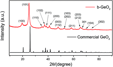
As schematically illustrated in Fig. 1, our synthesis approach of GeO2 is based on the self-assembly of a germanium precursor chelated by GeCl4 and ethylene glycol in the presence of aniline. Aniline, which acts as a base, may promote the growth and stabilization of the chelated germanium precursor by depletion of excess of the acid HCl, which is formed during the chelating process. It should be noted that GeO2 can readily react with alkali and thus it is important to select a weak base, such as aniline, which can not only absorb the acid arising from the reaction, but also prevent the dissolution of GeO2. Finally, mesoporous GeO2 can be spontaneously obtained via the removal of the organic phase using ethanol.The GeO2 phase of the b-GeO2 particles was characterized by powder X-ray diffraction analysis, as shown in Fig. 2. The XRD pattern can be indexed (ICDD# 36-1436) to a hexagonal structure of the P3221 (no. 1544) space group, and no impurity phase was observed.11 Meanwhile the positions of all peaks are in good agreement with commercial GeO2, except that commercial GeO2 presents sharper peaks. The synthesis process of our work was completely operated at room temperature without further heat-treatment, which can well explain the existence of broad peaks of the as-prepared material. Furthermore, the broadened peaks are an indication of a very small crystallite size.
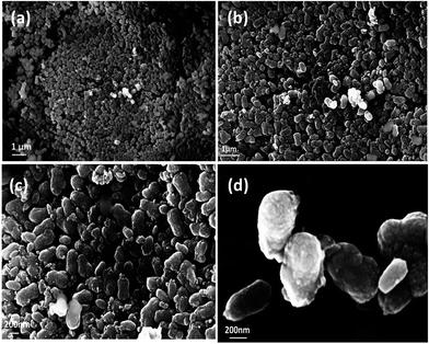
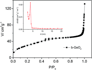
The as-prepared GeO2 shows a bean-like morphology with a particle size of 400 to 500 nm in length and 200 to 300 nm in diameter (Fig. 3a–d). It can be clearly observed that the as-made GeO2 particles exhibit a uniform morphology. In addition, the well-dispersed GeO2 shows no tendency to agglomerate, which will be favorable for its electrochemical performance. Furthermore, b-GeO2 shows a porous structure with a BET specific surface area of 112 m2 g−1, a pore volume of 0.163 cm3 g−1 and a pore size of about 3.6 nm, as depicted in Fig. 5, which is typical type H3 of a IV isotherm curve, representing the existence of the porous structure,30,31 in particular displaying mesopores.
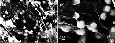
In a further step, we take advantage of graphene (a low-dimensional carbon material with high electronic conductivity and excellent mechanical properties; graphene can contribute to the capacity) to further enhance the electrochemical performance of b-GeO2.32,33 A spray drying method was employed to simply mix GeO2 and graphene (the morphology of graphene oxide is shown in Fig. S1, ESI†). As illustrated in Fig. 4, it can be clearly observed that GeO2 particles are tightly anchored on or wrapped within the graphene sheets. Notably, during the mixing process, GeO2 particles are still homogenously dispersed within or firmly encapsulated by the graphene sheets. To further determine the chemical distribution of the composite, energy dispersive X-ray spectroscopy (EDX) analysis was performed. Fig. S3 (see ESI†) shows the elemental mapping of the corresponding micrograph of the b-GeO2/graphene composite, in which carbon is settled everywhere, and GeO2 was found to be homogeneously distributed within the carbon phase.
The amount of graphene was determined by thermogravimetric analysis, as illustrated in Fig. S2 (see ESI†). The weight loss was observed from 200 °C to 700 °C; a rapid mass loss takes place between 500 °C and 650 °C. At 700 °C, the total mass loss is around 12%, so that the mass percentage ratio of graphene and GeO2 is calculated to be 12% and 88%, respectively.
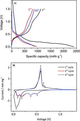
In Fig. 6a, the voltage vs. specific capacity profiles for the charge–discharge cycling process of b-GeO2 at a rate of 0.1 C in the first cycle (formation cycle) and 0.2 C in the following cycles are presented. With respect to the first cycle, the electrode gives a lithiation capacity of 2394 mAh g−1 and a high de-lithiation capacity of 1117 mAh g−1, which is almost equal to the theoretical capacity of GeO2 (1125 mAh g−1). However, the first cycle efficiency is only about 46.7% (see Table 1), which is quite low compared to currently used graphite-based anode materials. The large capacity loss can be ascribed to the irreversible reaction of GeO2 during the Li insertion process by formation of Li2O.18 Nevertheless, from the second cycle, the efficiency of the electrode was improved significantly and rises nearly to 99% after 50 cycles. The electrochemical lithiation/de-lithiation characteristics of the b-GeO2 material were determined using cyclic voltammetry (CV), as shown in Fig. 6b. Upon the initial cathodic sweep, a broad reduction peak can be observed at about 0.05 V. It is proposed that the reaction of GeO2 with Li involves two steps: (1) GeO2 + 4Li → Ge + 2Li2O; (2) xLi + Ge ⇌ LixGe (x ≤ 4.25). In the case of the first anodic potential sweep, one sharp oxidation peak around 0.55 V and a small broad peak at 0.65 V are revealed, which correspond to the Li extraction reaction. The subsequent cycles show four reduction peaks at 0.50 V, 0.36 V, 0.18 V and 0.09 V, which can be related to the lithium alloying reaction to form different LixGe alloys, as described by eqn (1),34,35 and only one oxidation peak at about 0.55 V, which are in good agreement with the electrochemical characteristics of metallic Ge.
| Lithiation: Ge → Li9Ge4 → Li7Ge2 → Li15Ge4 → Li22Ge5 | (1) |
| Cycle | b-GeO2/graphene | b-GeO2 | Commercial GeO2 | |
|---|---|---|---|---|
| De-lithiation capacity (0.1 C)/mAh g−1 | 1st | 1131 | 1117 | 1182 |
| Coulombic efficiency/% | 56.4 | 46.7 | 53.2 | |
| De-lithiation capacity (0.2 C)/mAh g−1 | 2nd | 1074 | 803 | 1146 |
| Coulombic efficiency/% | 99.3 | 83.5 | 96.1 | |
| De-lithiation capacity (0.2C)/mAh g−1 | 201st | 1043 | 845 | 514 |
| Coulombic efficiency/% | 99.8 | 98.8 | 99.7 | |
| Capacity retention after 200 cycles/% | 201st | 94.3 | 96.3 | 25.5 |
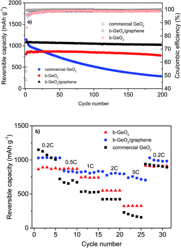
In order to demonstrate the improved electrochemical performance of b-GeO2 and its composite electrodes (b-GeO2/graphene), commercial GeO2 powder was studied under the same conditions for comparison. Fig. 7a shows the de-lithiation capacity curves as well as the Coulombic efficiency curves for the charge–discharge cycling of b-GeO2, b-GeO2/graphene and commercial GeO2 at a charge–discharge rate of 0.2 C (the first cycle is conducted at a rate of 0.1 C). Although commercial GeO2 provides a high initial reversible capacity of 1182 mAh g−1, a rapid capacity fade occurs from the very beginning of cycling, most likely due to the large volume variation, which results in the pulverization and electronic detachment of the active material. In contrast, the b-GeO2 electrode reveals a significantly improved cycle stability, which demonstrates a high reversible capacity of 845 mAh g−1 after 200 cycles, with nearly no capacity fading (according to the capacity of the 2nd cycle, see Table 1). The improved cycling performance can be ascribed to the existence of the mesoporous structure, which can offer sufficient inner space to absorb the volume changes of GeO2. By mixing GeO2 with graphene, the initial Coulombic efficiency, cycling performance as well as reversible capacity is further improved. The electrode gives a higher de-lithiation capacity of 1021 mAh g−1 with an initial efficiency of 56.4%, and the capacity retention is measured to be as high as 94.3% after 200 cycles. Moreover, from the second cycle, it is observed that the reversible capacity of the b-GeO2/graphene composite received a remarkable improvement. The coulombic efficiency is above 99.3% from the second cycle. The significantly improved electrochemical performance of the composite is mainly related to its stabilized whole structure, in which the GeO2 nanoparticles are firmly anchored on or wrapped within the graphene sheets. Together with the good flexibility of the graphene sheets, this composite material might effectively accommodate the big volume changes of GeO2 during lithiation. In addition, graphene can not only improve the electronic conductivity of GeO2 and therefore raise its utilization efficiency, but also contribute to the specific capacity of the composite.
Fig. 7b shows the rate capability of commercial GeO2, b-GeO2 and b-GeO2/graphene anode materials. The b-GeO2/graphene electrode delivers higher rate capability than the other electrodes, especially at high specific currents. It shows a high reversible capacity of 730 mAh g−1 even at 5 C, while b-GeO2 and commercial GeO2 only maintain 300 mAh g−1 and 180 mAh g−1, respectively. In particular, the charge–discharge profile of the b-GeO2/graphene composite exhibits a stable voltage plateau at about 0.2 V for lithium insertion at the high rate of 5 C (as shown in Fig. S4†), which is much higher than the metallic lithium potential. In contrast, the voltage of b-GeO2 and commercial GeO2 presents a quick drop towards 0 V during lithium uptake, which may result in the formation of metallic lithium or even lithium dendrites on the surface of the anode and therefore results in safety issues. As mentioned above, the excellent rate capability of the GeO2/graphene composite benefits from its uniformly dispersed mesoporous structure, in which the GeO2 particles are homogeneously distributed on or within the conductive graphene sheets, which also shortens the Li+ diffusion pathways. The open structure is favorable for fast transport of Li+ and gives rise to high rate performance.
4. Conclusions
In summary, a 3D mesoporous GeO2 material with a unique morphology was designed and developed via a facile and one-step synthesis process. The obtained mesoporous GeO2 particles present a bean-like morphology (b-GeO2), and display a good electrochemical charge–discharge cycling performance and rate capability for the lithiation/de-lithiation process. When graphene was employed via a spray drying method, the electrochemical performance of the b-GeO2/graphene composite was further significantly improved. The b-GeO2/graphene electrode gives a higher de-lithiation capacity of 1021 mAh g−1 at 0.2 C and the capacity retention is measured to be as high as 94.3% after 200 cycles. Furthermore, the composite displays an excellent rate performance even up to a charge–discharge rate of 5 C, where a reversible capacity of 730 mAh g−1 is obtained. However, the main drawback of GeO2, similar to the well-known SnO2-based anode materials, is its high irreversible capacity during the first lithiation due to the irreversible formation of Li2O. Nevertheless, there is potential to match these anode materials with Li-rich cathode materials for the application in lithium-ion full cells, in which the excessive Li source from the cathode material may compensate the large Li loss of the anode in the first cycle or with sacrificial metallic Li added to the anode mix. The excellent electrochemical cycling performance, a potential application in lithium-ion full cells and in particular the novel and facile synthesis route to a 3D mesoporous material make the GeO2 composite an interesting anode material for lithium-ion batteries.Acknowledgements
The authors wish to thank the German Research Foundation for funding this work in the project “WeNDeLIB” (Priority Programme 1473; Materials with New Design for Improved Lithium Ion Batteries). Furthermore, we gratefully acknowledge the supply of materials by Imerys Graphite & Carbon and Rockwood Lithium. We would also like to thank Wei Wei from Max Planck Institute (Polymer Research) for the constant help for TEM measurements.References
- J. B. Goodenough and Y. Kim, J. Power Sources, 2011, 196, 6688–6694 CrossRef CAS PubMed.
- J. F. Liang, W. Wei, D. Zhong, Q. L. Yang, L. D. Li and L. Guo, ACS Appl. Mater. Interfaces, 2012, 4, 454–459 CAS.
- R. Wagner, N. Preschitschek, S. Passerini, J. Leker and M. Winter, J. Appl. Electrochem., 2013, 43, 481–496 CrossRef CAS PubMed.
- M. N. Obrovac and L. Christensen, Electrochem. Solid-State Lett., 2004, 7, A93–A96 CrossRef CAS PubMed.
- S. Hossain, Y. K. Kim, Y. Saleh and R. Loutfy, J. Power Sources, 2003, 114, 264–276 CrossRef CAS.
- Y. Yu, L. Gu, C. Zhu, S. Tsukimoto, P. A. van Aken and J. Maier, Adv. Mater., 2010, 22, 2247–2250 CrossRef CAS PubMed.
- H. P. Jia, P. F. Gao, J. Yang, J. L. Wang, Y. N. Nuli and Z. Yang, Adv. Energy Mater., 2011, 1, 1036–1039 CrossRef CAS.
- W.-R. Liu, N.-L. Wu, D.-T. Shieh, H.-C. Wu, M. H. Yang, C. Korepp, J. O. Besenhard and M. Winter, J. Electrochem. Soc., 2007, 154, A97–A102 CrossRef CAS PubMed.
- W. M. Zhang, J. S. Hu, Y. G. Guo, S. F. Zheng, L. S. Zhong, W. G. Song and L. J. Wan, Adv. Mater., 2008, 20, 1160–1165 CrossRef CAS.
- M. Winter, J. O. Besenhard, J. H. Albering, J. Yang and M. Wachtler, Prog. Batteries Battery Mater., 1998, 17, 208–214 CAS.
- K. H. Seng, M.-H. Park, Z. P. Guo, H. K. Liu and J. Cho, Angew. Chem., Int. Ed. Engl., 2012, 51, 5657–5661 CrossRef CAS PubMed.
- M.-H. Park, Y. Cho, K. Kim, J. Kim, M. Liu and J. Cho, Angew. Chem., Int. Ed., 2011, 50, 9647–9650 CrossRef CAS PubMed.
- C. K. Chan, X. F. Zhang and Y. Cui, Nano Lett., 2008, 8, 307–309 CrossRef CAS PubMed.
- Y.-D. Ko, J.-G. Kang, G.-H. Lee, J.-G. Park, K.-S. Park, Y.-H. Jin and D.-W. Kim, Nanoscale, 2011, 3, 3371–3375 RSC.
- L. C. Yang, Q. S. Gao, L. Li, Y. Tang and Y. P. Wu, Electrochem. Commun., 2010, 12, 418–421 CrossRef CAS PubMed.
- R. A. DiLeo, S. Frisco, M. J. Ganter, R. E. Rogers, R. P. Raffaelle and B. J. Landi, J. Phys. Chem. C, 2011, 115, 22609–22614 CAS.
- W. Wei and L. Guo, Part. Part. Syst. Charact., 2013, 30, 658–661 CrossRef CAS.
- J. S. Pena, I. Sandu, O. Joubert, F. S. Pascual, C. O. Arean and T. Brousse, Electrochem. Solid-State Lett., 2004, 7, A278–A281 CrossRef CAS PubMed.
- Y. Kim, H. Hwang, K. Lawler, S. W. Martin and J. Cho, Electrochim. Acta, 2008, 53, 5058–5064 CrossRef CAS PubMed.
- J. S. Chen, C. M. Li, W. W. Zhou, Q. Y. Yan, L. A. Archer and X. W. Lou, Nanoscale, 2009, 1, 280–285 RSC.
- Z. P. Guo, G. D. Du, Y. Nuli, M. F. Hassan and H. K. Liu, J. Mater. Chem., 2009, 19, 3253–3257 RSC.
- F. Xiangpeng, L. Xia, G. Xianwei, M. Ya, H. Yong-Sheng, W. Jiazhao, W. Zhaoxiang, W. Feng, L. Huakun and C. Liquan, Electrochem. Commun., 2010, 12, 1520–1523 CrossRef PubMed.
- W.-M. Zhang, X.-L. Wu, J.-S. Hu, Y.-G. Guo and L.-J. Wan, Adv. Funct. Mater., 2008, 18, 3941–3946 CrossRef CAS.
- W. Wei, S. Yang, H. Zhou, I. Lieberwirth, X. Feng and K. Muellen, Adv. Mater., 2013, 25, 2909–2914 CrossRef CAS PubMed.
- D. T. Ngo, M. G. Chourashiya, S. W. Kim, C. N. Park and C. J. Park, 224th ECS Meeting – Meeting Abstracts, 2013, #1054 Search PubMed.
- J. K. Feng, M. O. Lai and L. Lu, Electrochim. Acta, 2012, 62, 103–108 CrossRef CAS PubMed.
- W. S. Hummers and R. E. Offeman, J. Am. Chem. Soc., 1958, 80, 1339 CrossRef CAS.
- Y. Liang, D. Wu, X. Feng and K. Muellen, Adv. Mater., 2009, 21, 1679–1683 CrossRef CAS.
- Y. EunJoo, J. Kim, E. Hosono, Z. Hao-shen, T. Kudo and I. Honma, Nano Lett., 2008, 8, 2277–2282 CrossRef PubMed.
- Z. Y. Ryu, J. T. Zheng, M. Z. Wang and B. J. Zhang, Carbon, 1999, 37, 1257–1264 CrossRef CAS.
- M. Kruk and M. Jaroniec, Chem. Mater., 2001, 13, 3169–3183 CrossRef CAS.
- S.-L. Chou, J.-Z. Wang, M. Choucair, H.-K. Liu, J. A. Stride and S.-X. Dou, Electrochem. Commun., 2010, 12, 303–306 CrossRef CAS PubMed.
- K. Evanoff, A. Magasinski, J. Yang and G. Yushin, Adv. Energy Mater., 2011, 1, 495–498 CrossRef CAS.
- G. L. Cui, L. Gu, L. J. Zhi, N. Kaskhedikar, P. A. van Aken, K. Mullen and J. Maier, Adv. Mater., 2008, 20, 3079–3083 CrossRef CAS.
- K. Min Gyu and C. Jaephil, J. Electrochem. Soc., 2009, 156, A277–A282 CrossRef PubMed.
Footnote |
| † Electronic supplementary information (ESI) available. See DOI: 10.1039/c4ta03933e |
| This journal is © The Royal Society of Chemistry 2014 |


