
 Open Access Article
 This Open Access Article is licensed under a Creative Commons Attribution-Non Commercial 3.0 Unported Licence
MeOx/SBA-15 (Me = Zn, Fe): highly efficient nanosorbents for mid-temperature H2S removal†
Mauro
Mureddu
ab,
Italo
Ferino
*a,
Anna
Musinu
ac,
Andrea
Ardu
ac,
Elisabetta
Rombi
a,
Maria Giorgia
Cutrufello
a,
Paolo
Deiana
d,
Marzia
Fantauzzi
a and
Carla
Cannas
*abc
aDipartimento di Scienze Chimiche e Geologiche, Università di Cagliari, s.s. 554 bivio per Sestu, 09042 Monserrato, CA, Italy. E-mail: ccannas@unica.it; ferino@unica.it
bConsorzio AUSI, Palazzo Bellavista Monteponi, 09016 Iglesias, CI, Italy
cINSTM, Cagliari Unit, Italy
dENEA, Centro Ricerche Casaccia, via Anguillarese 301, 00123 S. Maria di Galeria, Roma, Italy
First published on 29th September 2014
Abstract
Zinc oxide/ and iron oxide/SBA-15 composites were synthesized using the innovative Two-Solvents procedure and tested as sorbents for the mid-temperature (300 °C) removal of hydrogen sulphide, and then compared with a commercial unsupported ZnO sorbent. The sulphur retention capacity results showed the superior performance of the iron oxide/SBA-15 composite (401 mg S g−1 Fe2O3) in comparison with the zinc oxide/SBA-15 composite (53 mg S g−1 ZnO), both these sorbents being much more efficient than the commercial sorbent (6 mg S g−1 ZnO). The different sorption behaviour was discussed in terms of the nature of the nanocomposites where: (i) the mesostructure of the support was retained with a high surface area and pore volume; (ii) the zinc oxide phase was incorporated inside the SBA-15 channels as a thin amorphous homogeneous layer while the iron oxide was dispersed in form of small maghemite crystallites; and (iii) significant interactions occurred between the silica matrix and the zinc oxide phase. Remarkable differences in the regeneration behaviour of the exhaust sorbents were revealed by temperature-programmed experiments under an oxidizing atmosphere. After regeneration, the sorption properties of the zinc oxide/SBA-15 composite appeared to be enhanced compared to the commercial sorbent. Incomplete recovery of the sorption activity was observed for the regenerated iron oxide/SBA-15 sorbent, whose performance remained far better than that of the ZnO-based one, either fresh or regenerated. In view of its higher sulphur retention capacity and appropriate regeneration temperature (T ≤ 350 °C), the iron oxide/SBA-15 composite is a promising material for the design of advanced sorbents for a thermally efficient H2S removal process from hot gas streams.
Introduction
Hydrogen sulphide is one of the most noxious industrial gases that can pollute the atmosphere,1–3 as well as a powerful catalyst poison in many processes,4 and its concentration in feedstocks should be decreased to 10–100 ppb before their use.5 To accomplish this task, ZnO-based sorbents have been successfully employed for decades in different domains of the chemical industry. In view of its high equilibrium constant for sulphidation, pure zinc oxide is still used both as pure phase or modified by adding other metals.6,7 Given the large variety of process schemes, the optimum desulphurization temperature and the composition of the sorbents must be correspondingly adapted. Despite the differences in composition, the sorbents used in current industrial applications have similar textures, characterized by micrometer-sized particles. Utilization of unsupported nanostructured sorbents is not useful in these cases because nanoparticles would rapidly sinter at the high temperatures used during the sorption and/or regeneration steps. Moreover, the gas–solid H2S-oxide reaction occurs first at the surface and then extends to the bulk phase,8,9 often leaving an unreacted core.10A possible way to overcome such drawbacks could be the dispersion of the active phase nanoparticles onto a suitable, high-surface area support.11,12 The use of a support that is able to strongly interact with the active phase is inappropriate, as it could make difficult the regeneration of the spent sorbent.13 Microporous supports, such as zeolites, are inappropriate as well, due to the severe mass transfer limitations associated with their microporous system.14 To circumvent these problems, mesostructured SBA-15 is a promising support candidate because it is an amorphous silica material with high surface area, regular channels, and thick pore walls.15–18 In comparison with classical sorbents consisting of micrometer-sized particles, nanostructured oxides dispersed into SBA-15 channels would be sinter-resistant and would hence exhibit a higher reactivity towards H2S. Furthermore, the oxide/SBA-15 composite would behave as an ideal reactor, with the mesopores acting as channels for the rapid transport of the reactant.19
Enhanced desulphurization activity of ZnO/SBA-15 nanocomposites prepared by different impregnation strategies has recently been demonstrated in the present authors' laboratory.11 However, the slow kinetics of the reaction limits the sulphur-loading capacity of ZnO-based sorbents. Iron oxide/SBA-15 nanocomposites could be used as low-cost sorbents for H2S removal in view of the rapid kinetics of the H2S reaction with iron oxide.20–24 To the best of the present authors' knowledge, only one study dealing with the use of SBA-15 as a support for iron oxide-based sorbents has been published so far.25 In that work, an air stream containing a very low (0.1 vol%) H2S amount made contact at room temperature with iron oxide-loaded SBA-15 samples. However, in most industrial applications, significantly higher amounts of H2S need to be removed from air-free hot gases, as for instance in the case of coal-, hydrocarbon- or biomass-derived syngas. In case of a low or ambient temperature cleanup step, the gases require reheating for downstream processing, and it is apparent that if gasification, gas cleanup, and downstream processing were carried out at nearly the same temperature, the entire process would be more thermally efficient, i.e., both more economically viable and environmentally friendly. In addition to such practical implications, the fundamental chemistry indicates that iron oxide/SBA-15 composites are worthy of being investigated in parallel with zinc oxide/SBA-15 sorbents for mid- (300 °C) or high-temperature (>500 °C) H2S removal.
The present work deals with the synthesis and thorough characterization of both iron oxide/ and zinc oxide/SBA-15 composites, whose behaviour in H2S removal from gas streams was investigated at 300 °C with the aim of correlating the sorbent's performance with its physico-chemical features. The sorbents with similar loading (16–18 wt% of active phase) were prepared by the two-solvents hexane–water impregnation procedure.11,26,27 The behaviour of the iron oxide/ and zinc oxide/SBA-15 composites in the removal of H2S from an H2S–He stream was investigated in a fixed-bed reactor and compared with that of an unsupported ZnO commercial sorbent. The morphological, structural, and textural features of fresh, sulphided, and regenerated sorbents were assessed by a multi-technique approach, including the study of the possible interactions between the guest oxide and the host silica support. Zinc oxide as well as iron oxide in the form of a thin amorphous layer or small nanoparticles were highly dispersed into well-ordered mesoporous silica channels. The efficient incorporation of the active phase into SBA-15 induced a considerable improvement in the desulphurization performance compared to the commercial sorbent. Temperature-programmed oxidation (TPO) runs were carried out on the sulphided sorbent samples to elucidate the changes undergone by the solid during regeneration treatments. The influence of repeated sorption–regeneration cycles on the sorbent features was also investigated.
Experimental
Preparation of SBA-15 mesostructured silica
SBA-15 mesoporous silica with a long-range-order structure was prepared using neutral triblock copolymer Pluronic P123 (EO20PO70EO20, Sigma-Aldrich) as a surfactant template, according to the procedure reported by Zhao et al.15Preparation of sorbents
The MeOx/SBA-15 sorbents were prepared via a “Two-Solvents” synthetic route.11 In this procedure, 0.4 g of SBA-15 was first suspended in 12 cm3 of n-hexane (first hydrophobic solvent) and stirred at 400 rpm for 15 min; 0.48 cm3 of metal precursor (Zn(NO3)2·6H2O, Aldrich, 98%, 1 mmol or Fe(NO3)3·9H2O, Aldrich, 98%, 1 mmol) aqueous solution, corresponding to the SBA-15 pore volume previously determined by physisorption analysis (Vp = 1.2 cm3 g−1), was then added drop-wise. The resulting dispersion was vigorously stirred for two hours at room temperature and then left to dry in air at 40 °C overnight. Finally, the dried product was calcined at 500 °C for 2 hours (heating rate 2 °C min−1) to decompose the metal nitrates. The final metal oxide loading was assessed by inductively coupled plasma atomic emission spectrometry (ICP-AES) with a Varian Liberty 200 spectrophotometer. The active phase content was 18 and 16 wt% for zinc oxide- and iron oxide-based sorbent, respectively. The sorbent samples are labelled as Zn_X and Fe_X, where X denotes the state of the sorbent, F (Fresh), S (Sulphided) or R (Regenerated). Similar notation is also used for the commercial unsupported ZnO sorbent (KatalcoJM 32-5).Characterization of materials
Low-angle (2θ = 0.8–2.5°) and wide-angle (2θ = 10–70°) X-ray diffraction patterns were recorded on a Philips PanAnalytical X'Pert Pro diffractometer with θ–θ Bragg Brentano geometry with Cu Kα wavelength. Low-angle diffraction patterns were recorded using a zero-background silicon sample holder. The coherent domain (crystallite size) was obtained by Scherrer's equation using the Warren correction.28 Transmission electron microscopy (TEM) investigation was carried out using a JEOL 200CX microscope operating at an accelerating voltage of 200 kV. High resolution transmission microscope (HRTEM) images were collected using a JEOL 2010 UHR equipped with a Gatan Imaging Filter (GIF) with a 15 eV window and a 794 slow scan CCD camera. Finely ground samples were dispersed in n-octane and subjected to an ultrasonic bath, and the suspensions were then dropped on carbon-coated copper grids for the TEM and HRTEM observations. Textural analysis was carried out on a Sorptomatic 1990 system (Fisons Instruments) by determining the nitrogen adsorption–desorption isotherms at −196 °C. Prior to analysis, the samples were heated overnight under vacuum to 220 °C (heating rate 1 °C min−1). The Brunauer–Emmett–Teller (BET) specific surface area and pore volume were assessed from the adsorption data. The mean pore diameter was determined by applying the Barrett–Joyner–Halenda (BJH) model to the isotherm desorption branch.29 FTIR spectra were collected using a Bruker Equinox 55 spectrophotometer at room temperature in the 400 to 4000 cm−1 region. The samples were analyzed after dispersing the powders in KBr pellets. X-ray photoelectron spectroscopy analyses were performed using an ESCALAB200 spectrometer manufactured by Vacuum Generator Ltd., East Grinstead, U.K. A non-monochromatic Al Kα X-ray source (1486.6 eV, 15 mA, 20 keV) was used, and samples were analyzed as pellets. More details regarding the instrument configuration and data analysis have been reported elsewhere.30Desulphurization and regeneration activity evaluation of the sorbents
The desulphurization performance of the sorbents was evaluated at 300 °C using the breakthrough curves in a vertical quartz tubular reactor (10 mm I.D. × 20 mm length), coaxially located inside an electrical furnace. Quartz wool was used to support the sorbent bed (0.10 g) inside the reactor. Prior to the desulphurization run, helium gas was fed into the reactor for 30 min at 300 °C in order to remove any water and/or impurities adsorbed on the sorbent surface. The H2S–He reactant gas (1.5% H2S, He balance) was then admitted (inlet flow rate 20 cm3 min−1) into the reactor, and the H2S uptake during the adsorption test was monitored using a quadrupole mass spectrometer (Thermo Electron Corporation), where the detection limit of H2S was approximately 50 ppm. When the H2S concentration in the outlet gas reached 15![[thin space (1/6-em)]](https://www.rsc.org/images/entities/char_2009.gif) 000 ppmv, the inlet stream was halted and helium was introduced to purge the system. The breakthrough capacity or sulphur retention capacity (SRC), indicating the amount of sulphur retained per unit mass of sorbent, was determined when the outlet concentration of H2S attained 100 ppm by the formula
000 ppmv, the inlet stream was halted and helium was introduced to purge the system. The breakthrough capacity or sulphur retention capacity (SRC), indicating the amount of sulphur retained per unit mass of sorbent, was determined when the outlet concentration of H2S attained 100 ppm by the formulawhere Fs represents the mass flow rate of sulphur (mg s−1), Bt is the breakthrough time (s), and W indicates the sorbent weight (g), referring to either the pure active phase or the composite. After adsorption of H2S, the samples are referred to as “sulphided” (S) samples. The breakthrough time was assessed by subtracting the blank from the experimental profiles.

TPO runs were carried out on a Thermo Electron 1100 TPD/R/O apparatus equipped with both a thermal conductivity detector (TCD) and a quadrupole mass spectrometer (QMS). The sulphided samples were heated under flowing air (20 cm3 min−1) to 500 °C (heating rate 10 °C min−1), and then were subject to 500 °C for 4 h.
Results and discussion
Desulphurization activity of fresh sorbents
Breakthrough curves for all the sorbents, the pure zinc oxide commercial sorbent (KatalcoJM 32-5) included, were recorded at 300 °C (Fig. 1, ESI†). No H2S removal was detected for the bare SBA-15. For all the sorbents, the values of breakthrough time and sulphur retention capacity (SRC), expressed relative to either the active phase content or to the total composite amount (active phase + support), are reported in Table 1. The incorporation of zinc or iron oxide into SBA-15 induces a considerable improvement in the SRC compared to the commercial sorbent. The highest retention capacity per unit mass of active phase was obtained for Fe_F (401 mg S g−1 Fe2O3), which was more than seven-times higher than that of Zn_F (53 mg S g−1 ZnO), and much higher than the corresponding value for the commercial zinc oxide sorbent (6 mg S g−1 ZnO). The superior performance of the SBA-15-supported sorbents with respect to that of the commercial sample can be reasonably ascribed to differences in the exposure of the active phase to the reactant H2S. As reported in the following, although the surface area and the pore volume of the Fe_F are higher than that of the corresponding sorbent with zinc oxide, these textural properties cannot justify the tremendous enhancement of the SRC, as differences in the intrinsic kinetics should also be considered for explaining the sorption behaviour of Zn_F and Fe_F. | ||
| Fig. 1 XRD patterns of bare SBA-15, zinc oxide- and iron oxide-based sorbents in the fresh and sulphided state at low-angle (a) and wide-angle (b). The main reflection planes are marked. | ||
| Sample | B t (s) | SRC (mgS gactive phase−1) | SRC (mgS gsorbent−1) |
|---|---|---|---|
| KatalcoJM_F | 103 | 6 | 6 |
| Zn_F | 180 | 53 | 10 |
| Fe_F | 1350 | 401 | 80 |
Fresh sorbent characterization
Fig. 1 shows the XRD patterns of Zn_F and Fe_F compared with that of the bare SBA-15 at low- (a) and wide-angles (b). The low-angle diffraction pattern of the SBA-15 support exhibits three observable reflections, indexable as (100), (110) and (200), which are characteristic of a two-dimensional highly ordered hexagonal arrangement of the channels (space group P6mm). The low-angle diffraction patterns of the sorbents also exhibit three well-resolved diffraction peaks, which indicates that the organized pore structure is maintained despite the high active phase loading. A slight shift of the reflections towards higher angles can be observed for both sorbents, suggesting a small contraction of the cell parameters.The wide-angle diffraction pattern of Zn_F (Fig. 1b) shows only the typical halo of amorphous silica at 2θ = approximately 23°. No diffraction peaks corresponding to the ZnO phase are observable, indicating that the active phase is well dispersed into/over the support as an amorphous phase or as nanocrystals whose size is under the XRD detection limit. The pattern of Fe_F exhibits two further broad peaks at 2θ = 35.5° and 62.5° that can be attributed to the most intense reflections of the maghemite-Fe2O3 phase (PDF Card 39-1346).
Fig. 2 shows the nitrogen adsorption–desorption isotherms (a) and the pore size distribution plots (b) of the fresh sorbents (Zn_F and Fe_F) in comparison with bare SBA-15. The silica support exhibits a type IV isotherm with an H1 type hysteresis loop, characteristic of a mesoporous material with uniform cylindrical pores open at both ends.31 The mesoporous character of the solid is preserved after the incorporation of the active phase, as revealed by the type IV shape of the isotherm for both sorbents. A two-step desorption branch showing two inflection points at approximately P/P0 = 0.4 and 0.6 is observed for Fe_F, in contrast with the case of Zn_F, whose hysteresis loop is similar to that of the parent SBA-15. The calculated values of the surface area (SBET) and pore volume (Vp) are reported in Table 2. For Zn_F, SBET and Vp are much lower than the corresponding values of the bare support, which indicates partial filling of the mesopores by the metal oxide. For Fe_F, the surface area and pore volume values are also remarkably lower than those for the parent SBA-15. The pore size distribution plot for Zn_F (Fig. 2b) shows a narrow monomodal distribution centred at 6.2 nm. It is worthy of note that this value is slightly lower than that of SBA-15 (Fig. 2b). By subtracting the mean pore diameter from the unit cell parameter (a0, calculated from low-angle XRD data), the wall thickness (Tw) values were calculated, resulting in 5.0 and 5.2 nm for the bare SBA-15 and Zn_F, respectively (Table 2). Such a slight increase in the wall thickness as a consequence of ZnO deposition would be consistent with the presence of the oxide either as a layer or dispersed in clusters or very small nanoparticles. This is in agreement with the lack of ZnO reflections in the XRD pattern (Fig. 1b).
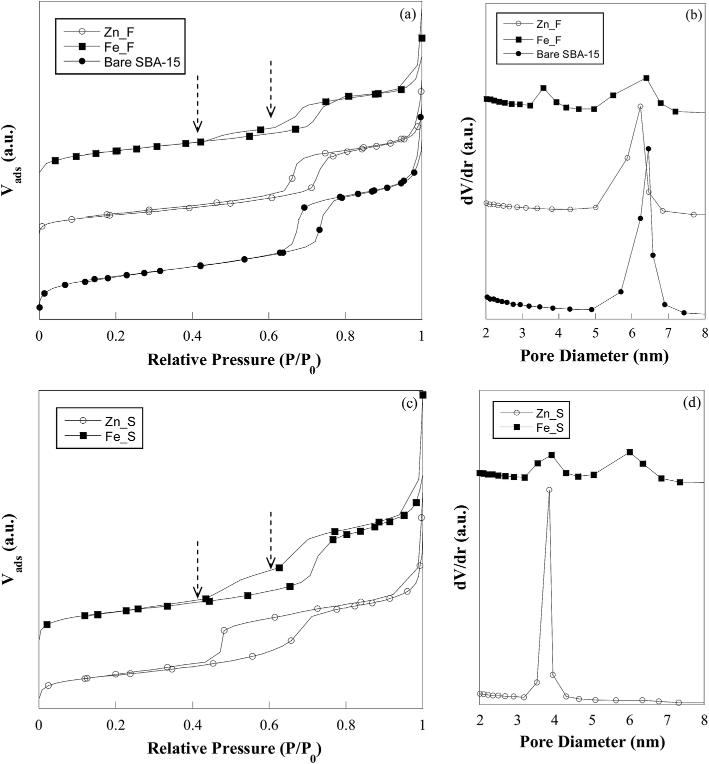 | ||
| Fig. 2 Nitrogen adsorption–desorption isotherms (a and c) and pore size distribution (b and d) of bare SBA-15, zinc oxide- and iron oxide-based sorbents in the fresh and sulphided state. | ||
| Sample | S BET (m2 g−1) | V p (cm3 g−1) | D p (nm) | T w (nm) |
|---|---|---|---|---|
| a S BET: BET specific surface area; Vp: pore volume; Dp: pore diameter; Tw: wall thickness = (a0 − Dp); a0: XRD unit cell parameter. Relative standard deviation: %RSD (SBET) = 2.1%; %RSD (Vp) = 1.1%; %RSD (Dp) = 1.8%. | ||||
| Bare SBA-15 | 770 | 1.20 | 6.4 | 5.0 |
| KatalcoJM_F | 9 | 0.10 | — | — |
| Zn_F | 482 | 0.90 | 6.2 | 5.2 |
| Zn_S | 406 | 0.76 | 3.8 | 7.2 |
| Zn_R | 332 | 0.69 | 5.4 | — |
| Fe_F | 545 | 0.87 | 3.6; 6.4 | — |
| Fe_S | 525 | 0.84 | 3.9; 6.0 | — |
| Fe_R | 463 | 0.80 | 3.5; 6.0 | — |
At variance with the case of the zinc oxide-containing sorbent, Fe_F shows a bimodal pore size distribution (Fig. 2b), which is related to the two-step feature observed in the desorption branch of the isotherm of this sample (Fig. 2a) and indicates that two distinct families of pores contribute to the overall pore volume. The family with a wider size (maximum at 6.4 nm) is responsible for the hysteresis at P/P0 = 0.6, which is typical of open-ended cylindrical mesopores, and reasonably are those pores of SBA-15 in which no deposition of iron oxide has occurred. The other pore family (maximum at 3.6 nm) is associated with the hysteresis loop closing at a relative pressure of approximately 0.4, which is suggestive of ink-bottle type mesopores resulting from the iron oxide deposition. Ink-bottle mesopores are characterized by a small neck in the pore through which the volume between two oxide particles would be accessible. Similar features were also observed by other authors in the desorption branch of zirconia- and iron oxide-containing SBA-15.32,33
Representative TEM images of SBA-15, Zn_F, and Fe_F are shown in Fig. 3. The well-ordered 2D-hexagonal symmetry of SBA-15 with regular empty mesochannels of approximately 6–7 nm in diameter and wall thickness of approximately 5 nm is clearly visible in Fig. 3a and b. TEM images of the Zn_F sorbent (Fig. 3c and d) do not show an evident variation when compared with bare SBA-15. No isolated ZnO particles are visible on the external surface or inside the pores of Zn_F. This suggests that the formation of an amorphous and quite uniform thin layer of zinc oxide has occurred on the inner surface of the pore walls, in agreement with the XRD and BET data. At variance with the case of Zn_F, the Fe_F images (Fig. 3f and g) show that iron oxide is not uniformly dispersed; note the rough contours of the channels, some of which appear completely filled, resulting from the deposition of the oxide nanoparticles. The crystalline nature of these nanoparticles is revealed by the high-resolution micrograph in the inset of Fig. 3f, where the calculated d spacing (0.25 nm) is in agreement with the (311) reflection of maghemite (PDF Card 39-1346).
 | ||
| Fig. 3 Representative TEM images of: bare SBA-15 viewed along (a) and perpendicular (b) to the axis of the hexagonal arranged mesopores; Zn_F (c and d); Zn_S (e); Fe_F (f and g); Fe_S (h). | ||
The different outcome of the oxide deposition process in the case of Zn_F and Fe_F could be justified by the different affinity of the zinc and iron cations for the silica host. According to previously published studies,34–36 silica depolymerization can occur in the presence of ZnO phases even at low treatment temperature, due to the occurrence of silanol group-oxide phase interaction. Conversely, no interaction between silanols and the oxide phase has been observed for a Fe2O3–SiO2 nanocomposite.37 Accordingly, the formation of the homogeneous zinc oxide nanolayer at the internal surface of the pores of Zn_F would be triggered by the above-cited interactions, whereas their lack would lead to nanoparticle deposition in the case of Fe_F.
In view of the possible role of host–guest interactions in determining the final active phase dispersion, which in turn would influence the performance of the sorbents, the latter were also investigated by FTIR. The spectra of the sorbents are reported in Fig. 4 and compared with the spectrum of the bare SBA-15. Most of the features are common to all the spectra: (i) the absorption bands at 1200–1080 and 800 cm−1 of the asymmetric and symmetric modes of Si–O–Si groups, respectively;38 (ii) the absorption band at 960 cm−1 of Si–OH stretching modes of the non-condensed Si–OH groups and the band at 465 cm−1 due to bending of the O–Si–O groups; and (iii) the absorption peak at approximately 1630 cm−1 of the H–O–H bending vibration of H2O adsorbed in capillary pores and on the surface. For both the sorbents, the absence of the typical narrow signal at approximately 1370 cm−1 due to the stretching vibration of the NO3− groups proves the complete decomposition of nitrates. Interestingly, the band at 960 cm−1 is still clearly visible after the incorporation of the iron oxide phase, whereas it is absent in the case of the Zn_F sorbent, which provides further evidence for the occurrence of interactions between the ZnO phase and the silica matrix.
 | ||
| Fig. 4 FTIR spectra of bare SBA-15, zinc oxide- and iron oxide-based sorbents in the fresh (F) and sulphided state (S). | ||
Further confirmation of this interaction was obtained by XPS analyses: the Zn2p3/2 signal of the Zn_F sorbent (Fig. 5a) shows a single component at 1022.7 ± 0.2 eV, while the kinetic energy of the Auger ZnLMM peak was found to be 986.3 ± 0.2 eV. These values indicate the formation of Si–O–Zn bonds, in agreement with the findings of other authors.39 Such interactions, which are responsible for the deposition of zinc oxide as an amorphous thin layer at the surface of the SBA-15 channels, also make the zinc oxide phase available to react with hydrogen sulphide, in comparison with the case of iron oxide nanoparticles that did not interact with the host matrix. As far as iron is concerned, in the Fe_F sorbent, the XPS Fe2p3/2 spectrum (Fig. 5b) shows only the presence of two components at 710.3 ± 0.2 eV and 711.6 ± 0.2 eV, which can be assigned to Fe(III) in Fe2O3 and FeOOH, respectively.40
 | ||
| Fig. 5 Zn2p3/2 (a) and Fe2p3/2 (b) XPS spectra of fresh and sulphided sorbents. (c) S2p XPS signals of Fe_S and Zn_S sorbents. | ||
Sulphided sorbent characterization
The low-angle diffraction patterns of the sulphided sorbents show that the characteristic hexagonal order is preserved in all of the samples (Fig. 1a). Only in the pattern of Zn_S, the (100), (110) and (200) peaks significantly shift towards higher angles as compared to those of the Zn_F pattern, suggesting a slight shrinkage in the mesoporous framework. The wide-angle XRD patterns of the sulphided sorbents (Fig. 1b) show that for Zn_S, in addition to the broad halo related to amorphous silica, broad and intense reflections at 28.6°, 47.7°, and 56.6° are present that are assigned to the ZnS phase (PDF Card 12-688). The mean size of the ZnS nanocrystals is estimated to be in the 3–4 nm range. The broadening of the reflections does not permit exclusion of the presence of an amorphous sulphided phase. A small peak centred at approximately 2θ = 33° is observed in the pattern of Fe_S and is attributed to the most intense reflection (200) of the FeS2 pyrite phase (PDF Card 71-2219). A large band overlapping with the main reflection of the pyrite phase could suggest the possible presence of an amorphous iron sulphide phase; the presence of unreacted maghemite cannot be excluded.Nitrogen physisorption isotherms (Fig. 2c) confirm the mesostructured character of the sulphided sorbents. As a consequence of the sulphidation process, zinc oxide is transformed into ZnS. Due to the different molar volume values of ZnO (15.07 cm3 mol−1) and ZnS (24.3 cm3 mol−1), an expansion in the volume of the guest material as high as 38% should be expected in case of complete ZnO/ZnS conversion. Such expansion should lead to a decrease in surface area and pore volume, which is actually observed (Table 2). The occurrence of an increase in the guest phase volume is also confirmed by the monomodal pore size distribution centred at 3.8 nm that is observed for the sulphided sorbent (Fig. 2d). Note in Table 2 that the wall thickness (Tw) value is significantly higher than the value for Zn_F. Due to the nanocrystalline nature of the ZnS phase and the increased electronic density contrast in comparison with zinc oxide, it is possible to discern in TEM micrographs (Fig. 3e) that the particles are mainly anchored at the channel walls, whose contours appear rather rough, with a rope-like profile. The image at higher magnification (Fig. 3e, inset) shows that in agreement with the wide-angle XRD results, the ZnS nanoparticles are 3–4 nm wide. The HRTEM image is shown as the inset of Fig. 3e and depicts two nanoparticles with d spacing values of 0.31 and 0.33 nm, which are in agreement with the (0010) and (100) reflections of the hexagonal ZnS phase (PDF Card 12-688), respectively.
Based on the sulphidation reaction stoichiometry, the conversion of Fe2O3 (30.71 cm3 mol−1) into FeS2 (51.06 cm3/2 mol) would be accompanied by an expansion in the volume of the guest material and would occur as a consequence of decreased surface area of the composite. The observed surface area and pore volume values for Fe_S are slightly lower than those for Fe_F (Table 2). The bimodal pore size distribution (Fig. 2d) is maintained in the sulphided sample, and the position of second peak in the pore size distribution of Fe_S that is centred at 6.0 nm, i.e., slightly lower than that for Fe_F, is in agreement with the presence of the iron sulphide phase occupying the pores. No significant differences between the fresh and sulphided sorbent are visible in the TEM micrographs for these samples (cf.Fig. 3f and h).
The FTIR spectra of the sulphided sorbents are provided in Fig. 4. A comparison between the spectra for Zn_F and Zn_S reveals that in the latter, the Si–OH band at 960 cm−1 reappears, hence suggesting that the Zn-containing phase formed upon sulphidation does not significantly interact with the silica surface. Interestingly, this occurs simultaneously with the transformation of the amorphous zinc oxide phase into a crystalline ZnS phase, as evidenced by the wide-angle XRD patterns (Fig. 1b). By contrast, in Fe_S, the band at 960 cm−1 is strongly attenuated, suggesting that interactions between the silica host and the iron sulphide guest phase take place to a remarkable extent. It is worthy of note that this is accompanied by the loss of the crystalline character of the iron oxide as a consequence of its transformation into the sulphided phase (cf.Fig. 1b). It is likely that the presence of the FeS2 phase, revealed by both the XRD pattern and the pale brass-yellow color of Fe_S, is responsible for the low-intensity band at 600 cm−1, in agreement with Philias.41 The pyrite formation is also consistent with the thermodynamic stability of this phase in comparison with the other iron sulphides.
The formation of both ZnS and FeS2 was confirmed by XPS analyses. The Zn2p3/2 signal (Fig. 5a) shows, together with the component at 1022.7 eV due to Zn involvement in the Si–O–Zn bonds, a component at lower binding energy values (1021.9 ± 0.2 eV), which can be assigned to ZnS. In the Fe2p3/2 signal (Fig. 5b), a component at 707.2 eV ± 0.2 eV was observed, which is due to pyritic iron.42 Sulphur S2p peaks of both Fe_S and Zn_S sorbents show a single component at 162.5 eV and at 162.0 eV, respectively, (Fig. 5c) that could be assigned to the sulphur in pyrite and in ZnS, respectively.43 Further confirmation of the presence of FeS2 and ZnS at the sorbent surfaces was obtained by stoichiometry calculated from the XPS data: the ratio between pyritic iron and sulphur was found to be 0.45, while the ratio of Zn/S, calculated by taking into account only the lower binding energy component of the zinc signal, was 1.10. All these results are in good agreement with the XRD analysis for both sorbents.
Sorbent regeneration
Sorbent regeneration determines the usable lifetime of a substance, and therefore, temperature-programmed oxidation experiments were carried out on the sulphided samples. In preliminary runs, a thermal conductivity detector (TCD) was used to monitor the effluent stream from a sample heated under flowing air (20 cm3 min−1) to 500 °C (heating rate 10 °C min−1), which was then subject to that temperature for 4 h; the sample was heated again to 700 °C and then subject to that temperature for 1 h. The TCD profiles (Fig. 2, ESI†) for Fe_S showed the presence of some peaks in the temperature region not exceeding 500 °C, with no further peaks being detected above this temperature. Conversely, in the case of Zn_S, in addition to a large peak at 500 °C, another peak was observed at 690 °C. It is worthy of note that for temperatures ≤ 500 °C, the oxidation of the sulphided commercial sample was almost negligible, and only a very low, enlarged signal was detected for such temperatures in the TCD profile. Heating of the sample well above 500 °C was required for significant oxidation to occur.As the TCD signal does not provide information regarding the species by which the single contributions originate, further runs were carried out in which the SO2 and O2 species in the outlet gas composition were simultaneously monitored by quadrupole mass spectrometer (QMS). All these runs were carried out at a temperature not exceeding 500 °C, in view of the detrimental effect of higher temperatures on the SRC of ZnO/SBA-15 sorbents.11 Another reason for the choice of temperature stems from previous 29Si MAS-NMR experiments,34 which revealed that the thermal treatment of sol–gel ZnO–SiO2 nanocomposites in the 500–700 °C range induces the depolymerization of the host matrix and the possible formation of zinc silicates as a consequence of its interaction with zinc oxide. Fig. 6 reports both the TCD and QMS signals for Fe_S. The TCD profile shows a peak at 185 °C and a broad contribution at 260 °C, as well as two well-resolved peaks at 322 °C and 345 °C. The QMS profiles for O2 and SO2 reveal that the peak at 185 °C and the broad contribution at 260 °C are due to O2 consumption and SO2 release, respectively. A second O2 consumption step is responsible for the narrow signal at 322 °C, which correlates with the successive release of a considerable amount of SO2 at 345 °C. The two different O2 consumption steps and subsequent SO2 formation steps are ascribable to the presence of two different sulphided species, one of which is reasonably the crystalline pyrite phase revealed by XRD. Inspection of the TCD and QMS profiles for Zn_S (Fig. 7) shows that both the unresolved TCD peak at 322 °C and the large peak at 500 °C stem from O2 consumption and the associated SO2 release. One of these two steps of Zn_S oxidation corresponds to the oxidation of a crystalline ZnS phase, whose presence was revealed by XRD, while the other could be ascribed to the oxidation of a zinc sulphide amorphous phase not visible by XRD.
 | ||
| Fig. 6 TPO profile and SO2 and O2 quadrupole mass spectrometer (QMS) signals of the Fe_S sulphided sorbent regenerated at 500 °C. | ||
 | ||
| Fig. 7 TPO profile and SO2 and O2 quadrupole mass spectrometer (QMS) signals of the Zn_S sulphided sorbent regenerated at 500 °C. | ||
Desulphurization–regeneration cycles and regenerated sorbent characterization
Repeated sorption–regeneration cycles were carried out in order to investigate the desorption behaviour and the stability of the regenerated sorbents. The Bt and SRC values for all the sorbents were obtained from the breakthrough curves (Fig. 8a and b) and are reported in Table 3. The regeneration process was unable to restore significant sorption activity for the ZnO commercial sample, with both the breakthrough time and the sulphur retention capacity of the regenerated sample (2 mg S g−1 ZnO vs. 6 mg S g−1 ZnO of the fresh sorbent) being dramatically lower than those of the fresh sorbent. Conversely, an enhanced performance of the regenerated sample in comparison with the fresh one was observed for the ZnO-based sorbent (68 mg S g−1 ZnO vs. 53 mg S g−1 ZnO of the fresh sorbent). For the iron oxide-based sorbent, the regeneration process resulted in the partial recovery of the original sorption activity (199 mg S g−1 Fe2O3vs. 401 mg S g−1 Fe2O3 of the fresh sorbent), with the Bt and SRC values for the regenerated sorbent being nearly halved in comparison with Fe_F. No further significant changes in the sorption behaviour were observed for any of the sorbents upon repeating the sorption–regeneration cycle. The superior features of the iron oxide-based sorbent are worthy of note: the breakthrough time and the sulphur retention capacity of the regenerated sample are far higher than those of the ZnO-based sorbent, in both the fresh or regenerated form. The poor performance of the regenerated commercial sample is not unexpected, as the TPO results showed that a thermal treatment well above 500 °C was required to convert the ZnS phase into the active oxide phase.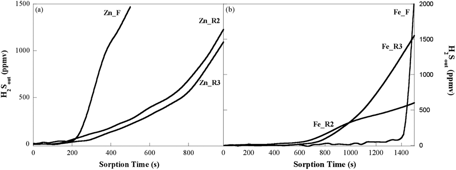 | ||
| Fig. 8 H2S breakthrough curves upon three sorption–regeneration cycles (S1, S2, S3) for the zinc oxide-based sorbent (a) and iron oxide-based sorbent (b). | ||
| Sample | Run numbera | B t (s) | SRC (mgS gactive phase−1) | SRC (mgS gsorbent−1) |
|---|---|---|---|---|
| a 1 = Fresh sorbent; 2 = After 1st regeneration; 3 = After 2nd regeneration. | ||||
| KatalcoJM_F | 1 | 103 | 6 | 6 |
| KatalcoJM_R | 2 | 26 | 2 | 2 |
| KatalcoJM_R | 3 | 26 | 2 | 2 |
| Zn_F | 1 | 180 | 53 | 10 |
| Zn_R | 2 | 230 | 68 | 13 |
| Zn_R | 3 | 250 | 74 | 14 |
| Fe_F | 1 | 1350 | 401 | 80 |
| Fe_R | 2 | 670 | 199 | 40 |
| Fe_R | 3 | 710 | 211 | 42 |
The results for the regenerated zinc oxide-based sorbent and the fresh sorbent were similar, as observed by XRD patterns (Fig. 3, ESI†) and the FTIR spectra (Fig. 4, ESI†). According to the data in Table 2, the surface area of Zn_R was significantly lower than that of Zn_F, although Zn_R exhibited an improved performance. Such enhancement in the sorption activity of the zinc oxide-based composite in cyclic operation is in agreement with the findings of a previous study on ZnO/SBA-15 sorbents with lower (10 wt%) and higher (30 and 60 wt%) zinc oxide content.11 No simple correlation exists between the accessibility parameters (SBET and Vp) and the sorbent performance. Based on the evidence of the previously mentioned study, it can be suggested that the ZnO phase originating from the ZnS oxidation during the regeneration step of the sorbent is different in terms of crystallinity, particle size, and texture from the one obtained directly by thermal decomposition of the zinc nitrate precursor, i.e., the regeneration process induces a reorganization of the zinc oxide nanophase.
For the iron oxide-based sorbent, a decrease in surface area occurs as a consequence of the regeneration process (Table 2), but the difference (15%) is too slight and cannot explain the observed halving of the Bt and SRC values. At variance with the case of the ZnO/SBA-15 sorbent, the XRD and FTIR techniques are able to reveal differences between the regenerated and fresh iron oxide/SBA-15 samples. After regeneration, the XRD reflections attributable to the sulphided phases disappear and diffraction peaks ascribable to maghemite phase are observed (Fig. 3, ESI†), although they are weaker and slightly broader than for Fe_F. This can be due to either a lower amount of maghemite phase or differences in its crystallinity, owing to a decrease in the crystalline domain size and/or accumulated strain. In the FTIR spectrum of the Fe_R sorbent (Fig. 4, ESI†), the Si–OH band at 960 cm−1 is less intense than that observed in the fresh sorbent, which suggests that there are weak interactions between the guest phase and the silica matrix for the Fe_R sorbent. Interestingly, two low-intensity signals at approximately 470 cm−1 and 610 cm−1 are observable, which indicate the presence of an iron sulphate phase that is not revealed in the XRD pattern.
For a better understanding of the changes undergone by the sorbent during the sulphidation–regeneration cycles, the investigation was extended to a pure nanostructured maghemite phase, which was first sulphided and then regenerated. For the sulphided sample, the corresponding XRD patterns (Fig. 5, ESI†) showed the presence of pyrrhotite (Fe1−xS) and pyrite (FeS2), as well as a minor amount of unreacted maghemite. The absence in the sulphided composite of the pyrrhotite phase is probably due to its metastability, enhanced by the nanodispersed nature of the sulphide. Interestingly, in addition to a remarkable amount of maghemite, the presence of iron sulphate (Fe2(SO4)3) was detected by XRD after regeneration by heating at 500 °C for 4 h. After heating to 700 °C, no sulphate phase was detected in the XRD pattern where only maghemite phase was present. Based on these data, the incomplete recovery of the sorption activity of the iron oxide/SBA-15 composite after the sorption–regeneration cycles can be ascribed to the presence of iron sulphate, which is inert towards H2S. Such an iron sulphate phase is not visible in the ESI† data of Fig. 3 because of the overlapping of its most intense peaks with the broad silica band at 2θ = approximately 23°.
The different behaviour of the regenerated sorbents in comparison with the fresh ones can hence be ascribed to different factors. In the case of the zinc oxide-based sorbent, an increase in the crystallinity of the ZnO phase originating from the ZnS oxidation during the regeneration step with respect to the crystallinity of the phase obtained directly by thermal decomposition of the zinc nitrate precursor would be responsible for the enhanced performance of the regenerated sorbent. In the case of the iron oxide-based sorbent, the formation during the regeneration step of an iron sulphate phase unable to react with H2S would explain the lack of complete recovery of the sorption capacity of the regenerated sorbent.
Conclusions
A simple, reproducible, easily scaled up, two-solvents incipient impregnation route has been used for dispersing zinc oxide and iron oxide inside the mesoporous channel system of SBA-15. The resulting nanocomposites have a remarkable ability to remove H2S from hot (300 °C) gas streams, the activity of the zinc oxide and the iron oxide systems being seven and seventy times higher than that of an unsupported zinc oxide commercial sorbent, respectively. The zinc oxide phase is incorporated as a thin amorphous homogeneous layer while the iron oxide phase is dispersed in the form of small maghemite crystallites. Differences in the morphology and the crystallinity of the active phase, as well as in the textural features of the composites, seem related to the lack or presence of interactions between the guest oxide phase and host silica matrix, which in turn cause the iron oxide and zinc oxide phases to react differently with hydrogen sulphide. After regeneration of the sulphided sample, the sorption properties of the zinc oxide/SBA-15 composite appear enhanced and are maintained upon repeating the sorption–regeneration cycle.The iron oxide/SBA-15 sorbent shows the highest sulphur retention capacity. Its performance significantly decreases at the second sorption cycle mainly due to the formation of an iron sulphate phase, but is retained at the third sorption cycle. This indicates that the amount of H2S-inert iron sulphate does not increase further. Noteworthy, although decreased in comparison with that of the fresh sample, the performance of the regenerated iron oxide-based sorbent is still far better than that of the ZnO-based one, either fresh or regenerated. The oxidation step for obtaining the regenerated iron oxide-based sorbent can be carried out at T ≤ 350 °C, which is considerably lower than that required in the case of the ZnO-based sample. In view of a possible application, this would be quite important for the thermal efficiency of the sorption–regeneration process.
Acknowledgements
Consorzio AUSI (Consorzio per la promozione delle Attività Universitarie del Sulcis-Iglesiente) is gratefully acknowledged for the grant financing for Mauro Mureddu PhD. This work was also supported by ENEA (Italian National Agency for New Technologies, Energy and Sustainable Economic Development). The use of the HRTEM facilities of C.G.S. (Centro Grandi Strumenti, University of Cagliari) is gratefully acknowledged. Thanks are due to MIUR (Italian Ministry of University and Research) for the fellowships of A. Ardu. The Sardinian Regional Government is gratefully acknowledged for financial support (P.O.R. Sardegna F.S.E. Operational Program of the Regione Autonoma della Sardegna, European Social Fund 2007-2013- Axis IV Human Resources, Objective 1.3, Line of Activity 1.3.1 “Avviso di chiamata per il finanziamento di Assegni di Ricerca”).References
- D. Stirling and J. H. Clark, in The sulfur problem: cleaning up industrial feedstocks, RSC, 2000, pp. 16–30, 10.1039/9781847552174-00016.
- U. M. Cowgill, Stud. Environ. Sci., 1984, 25, 233 CrossRef CAS.
- O. Badr and S. D. Probert, Appl. Energy, 1994, 47, 1 CrossRef.
- P. Dhage, A. Samokhvalov, D. Repala, E. C. Duin and B. J. Tatarchuk, Phys. Chem. Chem. Phys., 2011, 13, 2179 RSC.
- A. Samokhvalov and B. J. Tatarchuk, Phys. Chem. Chem. Phys., 2011, 13, 3197 RSC.
- T. Baird, K. C. Campbell, P. J. Holliman, R. W. Hoyle, M. Huxam, D. Stirling, B. P. Williams and M. Morris, J. Mater. Chem., 1999, 9, 599 RSC.
- H. F. Garces, A. E. Espinal and S. L. Suib, J. Phys. Chem. C, 2012, 116, 8465 CAS.
- S. P. Hernandez, M. Chiappero, N. Russo and D. Fino, Chem. Eng. J., 2011, 176–177, 272 CrossRef CAS PubMed.
- P. V. Ranade and D. P. Harrison, Chem. Eng. Sci., 1981, 36, 1079 CrossRef CAS.
- J. B. Gibson and D. P. Harrison, Ind. Eng. Chem. Process Des. Dev., 1980, 19, 231 CAS.
- M. Mureddu, I. Ferino, E. Rombi, M. G. Cutrufello, P. Deiana, A. Ardu, A. Musinu, G. Piccaluga and C. Cannas, Fuel, 2012, 102, 691 CrossRef CAS PubMed.
- D. Montes, E. Tocuyo, E. González, D. Rodríguez, R. Solano, R. Atencio, M. A. Ramos and A. Moronta, Microporous Mesoporous Mater., 2013, 168, 111 CrossRef CAS PubMed.
- T. H. Ko, H. Chu and L. K. Chaung, Chemosphere, 2005, 58, 467 CrossRef CAS PubMed.
- C. L. Hwang and N. H. Tai, Appl. Catal., B, 2010, 93, 363 CrossRef CAS PubMed.
- D. Zhao, J. Feng, Q. Huo, N. Melosh, G. H. Fredrikson, B. F. Chmelka and G. D. Stucky, Science, 1998, 279, 548 CrossRef CAS.
- C. Vogt, G. P. Knowles and A. L. Chaffee, J. Mater. Chem. A, 2014, 2, 4299 CAS.
- F. M. Zhang, B. S. Liu, Y. Zhang, Y. H. Guo, Z. Y. Wan and F. Subhan, J. Hazard. Mater., 2012, 233–234, 219 CrossRef CAS PubMed.
- B. S. Liu, X. N. Wei, Y. P. Zhan, R. Z. Chang, F. Subhan and C. T. Au, Appl. Catal., B, 2011, 102, 27 CrossRef CAS PubMed.
- J. A. Melero, G. Calleja, F. Martìnez and R. Molina, Catal. Commun., 2006, 7, 478 CrossRef CAS PubMed.
- P. J. H. Carnell and P. E. Starkey, Chem. Eng. J., 1984, 408, 30 CAS.
- J. A. Rodriguez, S. Chaturvedi, M. Kuhn and J. Hrbek, J. Phys. Chem. B, 1998, 102, 5511 CrossRef CAS.
- A. Davydov, K. T. Chuang and A. R. Sanger, J. Phys. Chem. B, 1998, 102, 4745 CrossRef CAS.
- S. S. Tamhankar and C. Y. Wen, Ind. Gas Sep., 1983, 223, 255 CAS.
- J. Deng, J. Ma, L. Mei, Y. Tang, Y. Chen, T. Lv, Z. Xu and T. Wang, J. Mater. Chem. A, 2013, 1, 12400 CAS.
- X. Wang, J. Jia, L. Zhao and T. Sun, Water, Air, Soil Pollut., 2008, 193, 247 CrossRef CAS.
- J. van der Meer, I. Bardez-Giboire, C. Mercier, B. Revel, A. Davidson and R. Denoyel, J. Phys. Chem. C, 2010, 114, 3507 CAS.
- F. Boubekr, A. Davidson, S. Casale and P. Massiani, Microporous Mesoporous Mater., 2011, 141, 157 CrossRef CAS PubMed.
- H. P. Klug and L. E. Alexander, in X-Ray diffraction procedures: for polycrystalline and amorphous materials, John Wiley & Sons, Inc., New York, 1954, ch. 9, pp. 491–538 Search PubMed.
- E. P. Barret, L. G. Joyner and P. P. Halenda, J. Am. Chem. Soc., 1951, 73, 373 CrossRef.
- M. Fantauzzi, A. Rigoldi, B. Elsener, D. Atzei and A. Rossi, J. Electron Spectrosc. Relat. Phenom., 2014, 193, 6 CrossRef CAS PubMed.
- F. Rouquerol, J. Rouquerol and K. Sing, in Adsorption by Powders and Porous Solids, Academic Press, 1999, ch. 7, pp. 191–217 Search PubMed.
- A. H. Jansen, C. M. Yang, Y. Wang, F. Schüth, A. J. Koster and K. P. de Jong, J. Phys. Chem. B, 2003, 107, 10552 CrossRef.
- E. Delahaye, V. Escax, N. El Hassan, A. Davidson, R. Aquino, V. Dupuis, R. Perzynski and Y. L. Raikher, J. Phys. Chem. B, 2006, 110, 26001 CrossRef CAS PubMed.
- C. Cannas, M. Casu, A. Lai, A. Musinu and G. Piccaluga, J. Mater. Chem., 1999, 9, 1765 RSC.
- Q. Jiang, Z. Y. Wu, Y. M. Wang, Y. Cao, C. F. Zhou and J. H. Zhu, J. Mater. Chem., 2006, 16, 1536 RSC.
- R. Anedda, C. Cannas, A. Musinu, G. Pinna, G. Piccaluga and M. Casu, J. Nanopart. Res., 2008, 10, 107 CrossRef CAS.
- S. Bruni, F. Cariati, M. Casu, A. Lai, A. Musinu, G. Piccaluga and S. Solinas, Nanostruct. Mater., 1999, 11, 573 CrossRef CAS.
- A. Bertoluzza, C. Fagnano, M. A. Morelli, V. Gottardi and M. Guglielmi, J. Non-Cryst. Solids, 1982, 48, 117 CrossRef CAS.
- Q. Jiang, Z. Y. Wu, Y. M. Wang, Y. Cao, C. F. Zhou and J. H. Zhu, J. Mater. Chem., 2006, 16, 1536 RSC.
- M. Fantauzzi, A. Pacella, D. Atzei, A. Gianfagna, G. B. Andreozzi and A. Rossi, Anal. Bioanal. Chem., 2010, 396, 2889 CrossRef CAS PubMed.
- J. M. Philias and B. Marsan, Electrochim. Acta, 1999, 44, 2351 CrossRef CAS.
- M. Fantauzzi, C. Licheri, D. Atzei, G. Loi, B. Elsener, G. Rossi and A. Rossi, Anal. Bioanal. Chem., 2011, 401, 2237 CrossRef CAS PubMed.
- M. Fantauzzi, D. Atzei, B. Elsener, P. Lattanzi and A. Rossi, Surf. Interface Anal., 2006, 38, 922 CrossRef CAS.
Footnote |
| † Electronic supplementary information (ESI) available. See DOI: 10.1039/c4ta03540b |
| This journal is © The Royal Society of Chemistry 2014 |