
 Open Access Article
 This Open Access Article is licensed under a Creative Commons Attribution-Non Commercial 3.0 Unported Licence
The effect of the pore-wall structure of carbon nitride on photocatalytic CO2 reduction under visible light
Kazuhiko
Maeda
*a,
Ryo
Kuriki
a,
Mingwen
Zhang
b,
Xinchen
Wang
b and
Osamu
Ishitani
a
aDepartment of Chemistry, Graduate School of Science and Engineering, Tokyo Institute of Technology, 2-12-1-NE-2 Ookayama, Meguro-ku, Tokyo 152-8550, Japan. E-mail: maedak@chem.titech.ac.jp
bState Key Laboratory of Photocatalysis on Energy and Environment, College of Chemistry, Fuzhou University, Fuzhou 350002, P. R. China
First published on 21st July 2014
Abstract
Carbon nitride (C3N4) polymers work as a vital component in a photocatalytic CO2 reduction assembly that operates under visible light when modified with a ruthenium complex, trans(Cl)-[Ru{4,4′-(CH2PO3H2)2-2,2′-bipyridine}(CO)2Cl2], (Ru) as a catalyst. Here we examined the effects of structural properties of carbon nitride on the photocatalytic performance for CO2 reduction into formic acid. Introduction of mesoporosity into the graphitic carbon nitride structure increased the specific surface area, leading to significant enhancement in activity. However, higher surface area (in other words, lower crystallinity) that originated from excessively introduced mesopores had a negative impact on activity, although it is a prerequisite to allow for adsorption of Ru on the carbon nitride surface. Thus, the activity was sensitive to specific surface area and crystallinity of carbon nitride, but is largely insensitive to the pore size and the volume.
Introduction
Development of a photochemical system that is capable of fixing CO2 to make energy-rich chemicals such as formic acid and carbon monoxide has attracted significant attention due to growing interest in artificial photosynthesis.1 Various materials including metal complexes,2–7 semiconductor powders,8–12 and their composites13,14 have been reported to function as electrocatalysts and/or photocatalysts for CO2 reduction. Very recently, a metal–organic framework with imidazolate linkers and cobalt redox centres was also found to work as a catalyst for capture and photochemical reduction of CO2.15 However, a satisfactory system has not been developed to date.Our group has very recently reported that photocatalytic CO2 reduction was achieved using a composite of a ruthenium complex, trans(Cl)-[Ru{4,4′-(CH2PO3H2)2-2,2′-bipyridine}(CO)2Cl2] (abbreviated as Ru), and mesoporous graphitic carbon nitride (mpg-CN) with visible light in the presence of triethanolamine that works as an electron donor and a proton source.14 Importantly, isotope-labelling experiments showed that the products obtained during the reaction originate not from the decomposition of C3N4 itself but from CO2 being used as the reactant. Although the number of papers that describe photocatalytic reactions on carbon nitride has been increasing since the initial report in 2009,16 most of them focus on hydrogen evolution from an aqueous solution containing sacrificial electron donors and/or the decomposition of organic substrates,17 and there are very few that describe photocatalytic CO2 reduction on carbon nitride with sufficient reliability. Our study14 was the first successful example of achieving CO2 reduction through the use of CN-based polymers with visible light. Note here that our system works at ambient pressure and room temperature, in contrast to the previous CO2 thermal activation and conversion scheme using carbon nitride that requires pressurized conditions (3–10 bar) and an elevated temperature (423 K).18
In this hybrid system, electrons and holes are generated in the conduction and valence bands of mpg-CN, respectively, under visible light irradiation (λ > 400 nm). The scheme of the reaction is depicted in Fig. 1. Upon photoexcitation of mpg-CN with visible light, electrons and holes are generated in the conduction band and valence band, respectively. The conduction band electrons move to adsorbed Ru molecules, thereby reducing CO2 into formic acid. Holes left in the valence band are, on the other hand, consumed by electron-donating species such as triethanolamine, and thus establishing the catalytic redox cycle. As this reaction is triggered by visible light absorption of mpg-CN, it is expected that the physicochemical properties, especially pore-wall chemistry of the material, have a significant impact on activity. The structure–activity relationship has been investigated in many different photocatalytic reactions with respect to various types of semiconductors, especially for water splitting.19 It should be stressed that in the heterogeneous photocatalysis research for CO2 reduction, however, such structural effects have not been investigated in detail not only for carbon nitride but also traditional metal-based semiconductor photocatalysts.17 Carbon nitride is one of the most studied semiconductor photocatalysts in recent years. Therefore, uncovering new functionalities of the material is an important mission in materials chemistry.
 | ||
| Fig. 1 A schematic illustration of photocatalytic CO2 reduction on the Ru/C3N4 composite under visible light illumination. | ||
In our previous communication,14 we have briefly described photocatalytic CO2 reduction using Ru and mpg-CN. However, no guideline for further improvement in the activity of this system has been established to date. In this study, photocatalytic activity of the Ru/CN composites for visible-light CO2 reduction was examined with respect to the pore-wall structure of CN polymers. Factors affecting the activity are discussed on the basis of the results of structural analyses and photocatalytic reactions.
Results and discussion
Structural characterization
First, we synthesized CN polymers having different porosities, and examined the applicability toward photocatalytic CO2 reduction. Mesoporous graphitic carbon nitride (mpg-CN) samples were prepared by heating cyanamide in air through the use of colloidal silicas that have different sizes as hard templates according to the original report by Thomas et al. with some modifications.20 The detail of the preparation is included in the Experimental section. The prepared samples will be referred to as CN-X-r, where X and r indicate the size of colloidal SiO2 and the SiO2/cyanamide ratio, respectively. Fig. 2A shows XRD patterns of mpg-CN prepared at different SiO2/cyanamide ratios, along with the data for non-porous g-CN for comparison. All samples exhibit a strong diffraction centred at 2θ = 27.4, which corresponds to the stacking of the conjugated aromatic system, as can be seen in graphite, with a distance of 0.326 nm. A small peak at 2θ = ca. 13, corresponding to 0.68 nm, is attributed to an in-planar repeating motif. With increasing the SiO2/cyanamide ratio, both of the two peaks became broader and less intense. When SiO2 colloids having different sizes were used while keeping the SiO2/cyanamide ratio of 1.0, the diffraction peaks became sharper and more intense (Fig. 2B) with an increase in the SiO2 size. These results indicate that as the SiO2/cyanamide ratio increases and the size of colloidal SiO2 decreases, the carbon nitride component tends to lose long-range atomic ordering (that is, crystallinity) both in-plane and stacking regions. | ||
| Fig. 2 XRD patterns of mpg-CN samples prepared with (A) different SiO2/cyanamide ratios using 12 nm SiO2 and (B) SiO2 having different sizes (SiO2/cyanamide ratio = 1.0), along with the data for non-porous g-CN for comparison. | ||
Fig. 3A shows nitrogen adsorption/desorption isotherms of mpg-CN prepared at different SiO2/cyanamide ratios using 12 nm colloidal SiO2 as the hard template. The curves exhibit a hysteresis typical of a material having randomly connected spherical pores. The specific surface areas increased from 50 to 240 m2 g−1 with an increase in the SiO2/cyanamide ratio in the synthesis, as listed in Table 1. Pore size distribution curves obtained through the BJH (Barrett–Joyner–Halenda) method are shown in Fig. 3B. The result indicated that the increasing SiO2/cyanamide ratio enlarged the pore volume in the mpg-CN structure, while maintaining the peak position of the pore size distribution (11–12 nm).
 | ||
| Fig. 3 (A) Nitrogen adsorption/desorption isotherms of mpg-CN samples prepared with different SiO2/cyanamide ratios using 12 nm SiO2. (B) The corresponding BJH pore size distributions. | ||
| Entry | Sample | Specific surface area/m2 g−1 | Pore volume/cm3 g−1 | Pore diameter/nm | Amount of formic acid produced/nmol |
|---|---|---|---|---|---|
a Reaction conditions: photocatalyst, Ru (3.9 μmol g−1)-loaded C3N4 8.0 mg; solution, a mixture of acetonitrile and triethanolamine (4![[thin space (1/6-em)]](https://www.rsc.org/images/entities/char_2009.gif) :1 v/v) 4 mL; reaction vessel, Pyrex test tube with a septum (11 mL capacity); light source, 400 W high-pressure Hg lamp with a NaNO2 solution filter.
b The amount of Ru adsorbed was 2.3 μmol g−1. Reaction time: 5 h. The reproducibility for formic acid production was within ∼10%. :1 v/v) 4 mL; reaction vessel, Pyrex test tube with a septum (11 mL capacity); light source, 400 W high-pressure Hg lamp with a NaNO2 solution filter.
b The amount of Ru adsorbed was 2.3 μmol g−1. Reaction time: 5 h. The reproducibility for formic acid production was within ∼10%.
|
|||||
| 1 | g-CNb | 6.1 | — | — | Trace |
| 2 | CN-12-0.2 | 54 | 0.20 | 12.2 | 1127 |
| 3 | CN-12-0.5 | 105 | 0.37 | 12.2 | 1854 |
| 4 | CN-12-1.0 | 200 | 0.64 | 10.7 | 1561 |
| 5 | CN-12-1.5 | 240 | 0.74 | 10.7 | Trace |
| 6 | CN-7-1.0 | 241 | 0.51 | 7.2 | Trace |
| 7 | CN-24-1.0 | 130 | 0.70 | 24.4 | 1223 |
Using colloidal SiO2 nanoparticles having different sizes but with the same SiO2/cyanamide ratio, mpg-CN samples were prepared in a similar manner. Nitrogen adsorption/desorption isotherms shown in Fig. 4A indicated that an uptake of nitrogen adsorbed due to capillary condensation shifted to higher relative pressures as the size of the SiO2 template increased. This is reasonable, considering the fact that the pore size of the materials thus obtained increased with an increase in the SiO2 size, as shown in Fig. 4B. The result of nitrogen adsorption measurements is consistent with that of XRD; that is, introduction of mesoporosity into the g-CN structure results in the loss of long-range atomic ordering.
 | ||
| Fig. 4 (A) Nitrogen adsorption/desorption isotherms of mpg-CN samples prepared with SiO2 having different sizes (SiO2/cyanamide ratio = 1.0). (B) The corresponding BJH pore size distributions. | ||
On the basis of these results, we concluded that mpg-CN samples with controlled porosity and pore size were successfully prepared by changing the size of colloidal SiO2 and the mixed ratio of SiO2 and cyanamide. The light-harvesting properties of the mpg-CN samples were investigated by means of UV-visible diffuse reflectance spectroscopy. As shown in Fig. 5, all samples exhibit a steep absorption edge at around 450 nm, which is due to band gap transition of electrons from the N2p valence band to the conduction band formed mainly by C2p orbitals, identical to g-CN.16 As shown in Fig. 5A, the absorption edge shifted slightly to shorter wavelengths with increasing mesoporosity. The same trend was observed in CN samples that have different pore diameters (Fig. 5B). It is also noted here that an absorption tail extending to 600 nm, attributable to surface defective sites, tends to be more pronounced with an increase in mesoporosity. It suggests that the introduction of mesoporosity increased the number of defective sites in the CN structure. This is reasonable considering the increased specific surface area of mpg-CN.
 | ||
| Fig. 5 Diffuse reflectance spectra of mpg-CN samples prepared with (A) different SiO2/cyanamide ratios using 12 nm SiO2 and (B) SiO2 having different sizes (SiO2/cyanamide ratio = 1.0), along with the data for non-porous g-CN for comparison. | ||
Photocatalytic activities
Using the as-prepared CN samples, we conducted CO2 reduction experiments with visible light (λ > 400 nm) by coupling with Ru as a catalyst to produce formic acid. In order to verify the catalytic activity of Ru, electrochemical measurements were conducted. Fig. 6 shows cyclic voltammograms of Ru in a DMF (dimethylformamide)/TEOA mixture containing 0.1 M tetraethylammonium tetrafluoroborate (Et4NBF4) as the supporting electrolyte under an Ar or a CO2 atmosphere. The first irreversible reduction wave started to occur at −1.57 V (vs. Ag/AgNO3). This is attributed to reduction of the bipyridine (bpy) ligand (bpy˙−/bpy). Under a CO2 atmosphere, the first reduction wave was more pronounced, and a clear catalytic CO2 reduction current was observable at around −1.9 V. This result clearly demonstrates that Ru possesses the ability to electrochemically reduce CO2. | ||
| Fig. 6 Cyclic voltammograms of Ru in DMF/TEOA (4:1 v/v) mixed solution containing 0.1 M Et4NBF4 as a supporting electrolyte under an Ar or a CO2 atmosphere. | ||
As indicated by our previous work, Ru does not have any noticeable absorption in the visible light region.14 Under >400 nm irradiation, therefore, only the carbon nitride component is excited by visible photons. Actually, Ru-loaded Al2O3 was found to give any carbon-containing product under the present reaction conditions.14 We first tried to compare the activity of g-CN with those of mpg-CN samples using the same amount of Ru. Mpg-CN samples tested in this study were capable of adsorbing Ru (3.9 μmol g−1) quantitatively, but bulk g-CN showed inferior affinity with the complex. As a result, g-CN showed negligible activity for the CO2 reduction reaction. In the edge of the graphitic plane in carbon nitride, there are –NH2 functional groups that work as hydrogen-bonding motifs.21 Obviously, the density of this motif should be increased with an increase in the density of the edge-plane; in other words, the specific surface area. This idea could qualitatively explain the difference in adsorption affinity between g-CN and mesoporous analogues, as the former has much lower specific surface area (6.1 m2 g−1) than the latter (∼240 m2 g−1). Fig. 7 shows a typical FT-IR spectrum of Ru/mpg-CN. The position of two peaks, assigned to the vibration mode of two carbonyl groups, in Ru/mpg-CN was the same as that in Ru dissolved in a KBr pellet. This result indicates that there is little electronic interaction between the adsorbed Ru and mpg-CN. This would be reasonable, considering –CH2– spacers between phosphoric acid groups and a bpy ligand cleaves electronic conjugation. The IR data also indicate that no significant change in the molecular structure of Ru occurred even after fixation onto the surface of mpg-CN; if an appreciable change such as ligand substitution occurs in Ru after adsorption, the positions of the vibration mode of two carbonyl groups should undergo a change more or less. On the basis of the experimental results, a possible form of linkage between the adsorbed Ru and mpg-CN is hydrogen-bonding that would be formed between –NH2 groups and the phosphonate anchors in Ru.
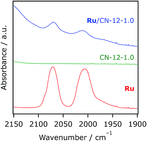 | ||
| Fig. 7 FT-IR spectra of CN-12-1.0, Ru, and Ru/CN-12-1.0 (Ru 39.5 μmol g−1) in KBr pellets. | ||
The results of photocatalytic CO2 reduction using mpg-CN samples are listed in Table 1. The activity for the production of formic acid was dependent strongly on the SiO2/cyanamide ratio as well as the size of the SiO2 template. Introduction of mesoporosity by increasing the ratio resulted in improvement of activity (entries 1–5). The fact that turnover numbers by far exceeded 1 (36–59 with respect to Ru) indicated catalytic cycles of the reactions. Interestingly, however, CN-12-1.5, which had the largest pore volume and specific surface area, showed little photocatalytic activity, despite its good affinity with Ru, as mentioned earlier. We also conducted control experiments to make sure that C3N4, Ru, CO2, and triethanolamine are all required to achieve appreciable formic acid formation. No reaction took place in the dark as well. In addition, it was confirmed that no HCOOH was detected when unmodified CN samples were used, indicating that there was no source of HCOOH, including the decomposition of the material itself, in these samples.
Changing the pore size also had a significant impact on activity. CN-7-1.0, which had the smallest pore size distribution and the largest specific surface area, showed negligible activity for the reaction. The performance of CN-24-1.0 having the largest pore diameter and the volume was slightly lower than that of CN-12-1.0. The highest performance was obtained with a sample prepared using 12 nm SiO2 with the SiO2/cyanamide ratio of 0.5–1.0.
Factors affecting photocatalytic activity
The significant difference in activity highlighted in Table 1 should be attributable to the different structural properties, as shown in Fig. 2–5. Photogenerated electrons and holes in the bulk region of a given CN material have to travel without recombination to reach the surface. With decreasing the “wall” thickness of CN by the introduction of mesoporosity, the distance for electron–hole migration should be shortened, resulting in more chance to participate in surface redox events. A larger specific surface area is also beneficial to provide more active site for surface reactions. These ideas could explain the increase in activity with increasing pore volume (entries 2–4, Table 1). However, too much introduction of mesoporosity had significant drop in activity (entry 5). Increasing the pore volume in the bulk CN polymers increases the density of dangling bonds due to an increase in the surface area. In such a situation, the density of defect sites that can trap photogenerated charge carriers should be increased.22 As a result, photocatalytic activity would be decreased. For the degradation of organic pollutants using CN materials in the presence of O2, the increased density of electron trapping sites might be beneficial because photoreduction of O2 is accelerated.23 Interestingly, however, it appears that electrons trapped at such defects do not transfer to the adsorbed Ru molecules. Another important result is that bulk g-CN showed negligible activity for the CO2 reduction reaction, even though Ru was adsorbed (although not quantitatively), as shown in Table 1 (entry 1). Therefore, the introduction of mesoporosity into the bulk g-CN structure is essential to induce the potential for use as a component in this CO2 photoreduction assembly.We have previously reported the conduction band potentials of g-CN and mpg-C3N4,14,17b which are −1.46 and −1.29 V vs. Ag/AgCl at pH 6.6, respectively. They can be converted to −1.82 and −1.65 V vs. Ag/AgNO3, respectively. It is thus clear that electron transfer from the conduction band of CN materials to Ru, which has the first reduction potential of ca. −1.57 V, is energetically possible. One may also think that the more negative conduction band potential of g-CN than mpg-CN is more favorable for the CN-to-Ru electron transfer. However, the CO2 reduction activity of g-CN was negligibly low, compared to that of mpg-CN (entry 1). This again supports the importance of the mesoporous structure for efficient charge utilization and the subsequent CO2 reduction event.
It should be noted that CN-24-1.0, which has relatively large pore volume, showed activity for the reaction (entry 7). Judging from the reaction data using CN-12-1.5 (entry 5) that has almost the same pore volume (∼0.7 cm3 g−1) as CN-24-1.0 but with much larger surface area, the activity appears to be largely insensitive to the pore volume, but is related to the specific surface area. In other words, there is a trade-off between activity and specific surface area. A larger specific surface area is actually important in terms of adsorption of the Ru catalyst as well as the distance of electron–hole migration, but can lead to more chance to electron–hole recombination.
Conclusions
Photocatalytic assemblies that consist of a carbon nitride semiconductor having different pore structures and a ruthenium complex catalyst were constructed to reduce CO2 into formic acid under visible light (λ > 400 nm) in the presence of triethanolamine as an electron donor and a proton source under mild conditions. The activity depended strongly on the structure of carbon nitride used. Introducing mesoporosity, which can shorten the length of electron–hole migration and increase the density of adsorption sites for the Ru catalyst, is essential to enhance the activity for CO2 reduction. The activity is independent largely on the pore size and the volume, but is sensitive to specific surface area. However, too much introduction of mesoporosity resulted in shrinkage of carbon nitride walls, increasing the density of defects and eventually contributing to an activity-drop.Experimental section
Synthesis of carbon nitride polymers
Carbon nitride polymers were prepared according to the method reported previously with some modifications.20 First, cyanamide (Alfa Aesar, >98%) was dissolved in different amounts of a 40% dispersion of colloidal SiO2 particles in water. Colloidal SiO2 samples were purchased from Aldrich (LUDOX SM-30, LUDOX HS-40, and LUDOX TM-40) whose SiO2 sizes are 7, 12, and 24 nm, respectively. To control the porosity, the ratio of SiO2 to cyanamide (represented hereafter as r) was changed from 0.2 to 1.5. After the mixture was subject to stirring at 333 K overnight, the resulting transparent mixture was heated at a rate of 2.3 K min−1 over 4 h to reach a temperature of 823 K, keeping this temperature for another 4 h. The resulting brown-yellow powder was treated with an aqueous NH4HF2 (4 M) solution, purchased from Sinopharm Chemical Reagents Co. (>98.0%), for 24 h to remove the silica template. Special attention should be paid to handle NH4HF2. The powders were corrected by centrifugation, followed by washing with distilled water three times and twice with ethanol. Finally the powders were dried at 343 K under vacuum overnight. The product thus-obtained will be referred to as CN-X-r, where X and r indicate the size of colloidal SiO2 and the SiO2/cyanamide ratio, respectively. For example, CN-12-0.5 means a mpg-C3N4 sample prepared using 12 nm colloidal SiO2 with the SiO2/cyanamide ratio of 0.5. For comparison, bulk-type g-C3N4 was prepared in a similar manner without using a SiO2 template, and will be represented hereafter as g-CN.Synthesis of trans(Cl)-[Ru{4,4′-(CH2PO3H2)2-2,2′-bipyridine}(CO)2Cl2] and adsorption onto the C3N4 surface
The synthesis was conducted according to the method by Anderson et al.24 It was confirmed by 1H-NMR spectroscopy, FT-IR spectroscopy and elemental analysis that the complex, Ru, was successfully synthesized.Ru was adsorbed onto the surface of C3N4 at room temperature. C3N4 (50 mg) was dispersed in methanol (25 mL) containing an appropriate amount of Ru under continuous stirring in the dark to establish adsorption/desorption equilibrium. After 20–24 h, the solid was separated from the suspension by filtration, and the resulting supernatant was then analysed by using a UV-visible spectrometer (Jasco, V-565). The amount of Ru adsorbed was calculated from the difference in absorbance between the initial solution and the supernatant. The resulting solid sample was washed with methanol several times, and was dried under vacuum at room temperature overnight. The amount of Ru loading was 3.9 μmol g−1 unless otherwise stated. The coverage of Ru (3.9 μmol g−1) on mpg-CN having specific surface areas of 50–240 m2 g−1 corresponds approximately to 0.6–2.9%.
Characterization of catalysts
The prepared CN samples were characterized by X-ray diffraction (XRD; MiniFlex 600, Rigaku), UV-visible diffuse reflectance spectroscopy (DRS; V-565, Jasco), and FT-IR spectroscopy (FT/IR-610, Jasco). The Brunauer–Emmett–Teller (BET) surface areas of samples were also measured using a BELSORP-mini apparatus (BEL Japan) at liquid nitrogen temperature (77 K).Electrochemical measurements
Cyclic voltammograms of Ru were measured in a mixture of DMF–TEOA (4:1 v/v) containing Et4NBF4 (0.1 M) as the supporting electrolyte using a BAS CHI620 electrochemical analyser and a conventional three-electrode type cell at room temperature under an Ar or a CO2 atmosphere. A glassy-carbon electrode with a diameter of 3 mm, a platinum wire electrode and an Ag/AgNO3 (0.01 M) electrode were employed as the working, counter, and reference electrodes, respectively. The concentration of Ru dissolving in the electrolyte solution was 0.5 mM and the scan rate was 200 mV s−1.
Photocatalytic reactions
The procedure was essentially the same as reported previously.14 Reactions were conducted at room temperature using an 11 mL test tube that contains 4 mL of solution (20 vol% triethanolamine in acetonitrile) and 8 mg of photocatalyst powder. A 400 W high-pressure Hg lamp (SEN) was employed as a light source, in combination with an aqueous NaNO2 solution to allow for visible light irradiation (λ > 400 nm). Prior to irradiation, the suspension was purged with CO2 (Taiyo Nippon Sanso Co., >99.995%) for 20–30 min. The gaseous reaction products H2 and CO were analysed using a gas chromatograph with a TCD detector (GL science, GC323), an active carbon column, and argon carrier gas. Formic acid in the liquid phase was analysed using a capillary-electrophoresis system (Otsuka Electronics Co. CAPI-3300). Before analysis, the reacted solution was subject to filtration to remove the photocatalyst particle. After diluting the resulting solution with H2O (1:10 v/v), analyses by capillary-electrophoresis were carried out.
Acknowledgements
K. M. acknowledges a start-up funding of the Faculty of Science, Tokyo Institute of Technology, and Grant-in-Aid for Scientific Research on Innovative Areas (Project no. 25107512). Acknowledgements are also extended to a PRESTO/JST program “Chemical Conversion of Light Energy” and Grant-in-Aid for Young Scientists (A) (Project no. 25709078).Notes and references
- (a) A. J. Morris, G. J. Meyer and E. Fujita, Acc. Chem. Res., 2009, 42, 1983 CrossRef CAS PubMed; (b) H. Takeda and O. Ishitani, Coord. Chem. Rev., 2010, 254, 346 CrossRef CAS PubMed; (c) A. Corma and H. Garcia, J. Catal., 2013, 308, 168 CrossRef CAS PubMed; (d) S. N. Habisreutinger, L. Schmidt-Mende and J. K. Stolarczyk, Angew. Chem., Int. Ed., 2013, 52, 7372 CrossRef CAS PubMed.
- (a) J. Hawecker, J. M. Lehn and R. Ziessel, J. Chem. Soc., Chem. Commun., 1983, 536 RSC; (b) H. Takeda, K. Koike, H. Inoue and O. Ishitani, J. Am. Chem. Soc., 2008, 130, 2023 CrossRef CAS PubMed.
- H. Ishida, K. Tanaka and T. Tanaka, Organometallics, 1990, 6, 181 CrossRef.
- Y. Tamaki, T. Morimoto, K. Koike and O. Ishitani, Proc. Natl. Acad. Sci. U. S. A., 2012, 109, 15673 CrossRef CAS PubMed.
- H. Takeda, H. Koizumi, K. Okamoto and O. Ishitani, Chem. Commun., 2014, 50, 1491 RSC.
- S. Sato, T. Morikawa, T. Kajino and O. Ishitani, Angew. Chem., Int. Ed., 2013, 52, 988 CrossRef CAS PubMed.
- Y. Kuramochi, M. Kamiya and H. Ishida, Inorg. Chem., 2014, 53, 3326 CrossRef CAS PubMed.
- Y. Kohno, T. Tanaka, T. Funabiki and S. Yoshida, Chem. Lett., 1997, 993 CrossRef CAS.
- T. Yui, A. Kan, C. Saitoh, K. Koike, T. Ibusuki and O. Ishitani, ACS Appl. Mater. Interfaces, 2011, 3, 2594 CAS.
- H. Tsuneoka, K. Teramura, T. Shishido and T. Tanaka, J. Phys. Chem. C, 2010, 114, 8892 CAS.
- K. Iizuka, T. Wato, Y. Miseki, K. Saito and A. Kudo, J. Am. Chem. Soc., 2011, 133, 20863 CrossRef CAS PubMed.
- K. Teramura, S. Iguchi, Y. Mizuno, T. Shishido and T. Tanaka, Angew. Chem., Int. Ed., 2012, 51, 8008 CrossRef CAS PubMed.
- (a) S. Sato, T. Morikawa, S. Saeki, T. Kajino and T. Motohiro, Angew. Chem., Int. Ed., 2010, 49, 5101 CrossRef CAS PubMed; (b) T. M. Suzuki, H. Tanaka, T. Morikawa, M. Iwaki, S. Sato, S. Saeki, M. Inoue, T. Kajino and T. Motohiro, Chem. Commun., 2011, 47, 8673 RSC; (c) K. Sekizawa, K. Maeda, K. Koike, K. Domen and O. Ishitani, J. Am. Chem. Soc., 2013, 135, 4596 CrossRef CAS PubMed.
- K. Maeda, K. Sekizawa and O. Ishitani, Chem. Commun., 2013, 49, 10127 RSC.
- S. Wang, W. Yao, J. Lin, Z. Ding and X. Wang, Angew. Chem., Int. Ed., 2014, 53, 1034 CrossRef CAS PubMed.
- X. Wang, K. Maeda, A. Thomas, K. Takanabe, G. Xin, J. M. Carlsson, K. Domen and M. Antonietti, Nat. Mater., 2009, 8, 76 CrossRef CAS PubMed.
- (a) Y. Wang, X. Wang and M. Antonietti, Angew. Chem., Int. Ed., 2012, 51, 68 CrossRef CAS PubMed; (b) X. Wang, S. Blechert and M. Antonietti, ACS Catal., 2012, 2, 1596 CrossRef CAS.
- F. Goettmann, A. Thomas and M. Antonietti, Angew. Chem., Int. Ed., 2007, 46, 2717 CrossRef CAS PubMed.
- (a) A. Kudo and Y. Miseki, Chem. Soc. Rev., 2009, 38, 253 RSC; (b) K. Maeda, J. Photochem. Photobiol., C, 2011, 12, 237 CrossRef CAS PubMed; (c) Y. Inoue, Energy Environ. Sci., 2009, 2, 364 RSC.
- F. Goettmann, A. Fischer, M. Antonietti and A. Thomas, Angew. Chem., Int. Ed., 2006, 45, 4467 CrossRef CAS PubMed.
- A. Thomas, A. Fischer, F. Goettmann, M. Antonietti, J.-O. Müller, R. Schlögl and J. M. Carlsson, J. Mater. Chem., 2008, 18, 4893 RSC.
- X. Wang, K. Maeda, X. Chen, K. Takanabe, K. Domen, Y. Hou, X. Fu and M. Antonietti, J. Am. Chem. Soc., 2009, 131, 1680 CrossRef CAS PubMed.
- Y. Cui, J. Huang, X. Fu and X. Wang, Catal. Sci. Technol., 2012, 2, 1396 CAS.
- P. A. Anderson, G. B. Deacon, K. H. Haarmann, F. R. Keene, T. J. Meyer, D. A. Reitsma, B. W. Skelton, G. F. Strouse and N. C. Thomas, Inorg. Chem., 1995, 34, 6145 CrossRef CAS.
| This journal is © The Royal Society of Chemistry 2014 |