 Open Access Article
Creative Commons Attribution 3.0 Unported Licence
Spray-deposited zinc titanate films obtained via sol–gel synthesis for application in dye-sensitized solar cells†
Kuhu
Sarkar
a,
Erik V.
Braden
a,
Thomas
Fröschl
b,
Nicola
Hüsing
b and
Peter
Müller-Buschbaum
*ac
aTechnische Universität München, Physik-Department, Lehrstuhl für Funktionelle Materialien, James-Franck-Straße 1, 85748 Garching, Germany. E-mail: muellerb@ph.tum.de; Fax: +49-89-289-12473; Tel: +49-89-289-12451
bMaterialchemie, FB Materialforschung und Physik, Universität Salzburg, Hellbrunnerstraße 34, 5020 Salzburg, Austria. E-mail: nicola.huesing@sbg.ac.at; Tel: +43-662-8044-5404
cNanosystems Initiative Munich, Schellingstraße 4, 80799 München, Germany
First published on 22nd July 2014
Abstract
Foam-like zinc orthotitanate (Zn2TiO4) is successfully synthesized via the wet chemical sol–gel route assisted with a structure-directing diblock copolymer template. The wet chemical route enables spray deposition of Zn2TiO4 films. Calcination temperature of the spray-deposited films is shown to be crucial for the synthesis of the compound phase, Zn2TiO4. Surface composition and optical properties of the films are also studied. Finally, Zn2TiO4 films are shown to offer a reasonable functioning as an electron acceptor in dye-sensitized solar cells, with the best preliminary performance reported so far.
Introduction
Evolution of highly ordered inorganic metal oxide nanostructures has gained substantial momentum in recent years, owing to their extraordinary structural and electronic properties. The tremendous increase in the demand for nanoscale electronic devices1,2 has motivated researchers to produce complex functional nanomaterials consisting of binary and/or ternary composites in addition to pure phases. In the present investigation, we focus on the synthesis of a ternary compound, namely, zinc orthotitanate in a solution-based sol–gel approach. As reported in literature, the simultaneous synthesis of TiO2–ZnO nanocomposites gives rise to three different compounds and some minor impurities. These three compounds are: zinc orthotitanate (Zn2TiO4) with a cubic spinel structure, Zn2Ti3O8 with a cubic defect spinel structure and zinc metatitanate (ZnTiO3) with a rhombohedral ilmenite structure. The minor impurity phases consist of rutile TiO2 or ZnO. Zn2Ti3O8 is a metastable form of ZnTiO3 and is known to occur at temperatures lower than 800 °C, whereas, ZnTiO3 is well-known to decompose to Zn2TiO4 and rutile TiO2 at temperatures above 945 °C.3 Hence, the production of a pure composite is a challenge resulting from the temperature requirements for the synthesis of a particular compound.Among the three reported common compounds, Zn2TiO4 is the center of interest in the present work due to its high potential for several applications. Zn2TiO4 has been established as one of the most important regenerable photocatalysts, additionally showing wide-scale applications in the removal of sulfur during coal gasification,3 photocatalytic splitting of water and degradation of organic compounds, as an active anode material in Li-ion batteries, microwave dielectrics, pigments and many more.4 A major field of application, where inorganic metal oxides have largely contributed, is in energy conversion and storage. In particular, dye-sensitized solar cells (DSSCs) is one of the most successful technologies for the conversion of solar energy into electricity.5,6 Conventionally, TiO2 has been used for DSSCs,7 however, more recent studies have shown promising results for ZnO-based DSSCs as well.8 In addition, several attempts have been made in order to combine these two materials together to harvest their synergetic structural and electronic properties.8–10 These initiatives have inspired us to prove the competence of the titania (TiO2)–zinc oxide (ZnO) compound, Zn2TiO4 in the field of DSSCs. The present article is focused on the synthesis procedure to obtain a pure compound phase of Zn2TiO4via a wet chemical route and its characterization rather than device optimization. Nevertheless, to our knowledge, this is the first contribution so far, reporting a reasonable device efficiency using Zn2TiO4.
The most common technique to synthesize Zn2TiO4 is the direct solid-state route employing a high temperature of 1000 °C.3 Other methods producing pure and mixed phases of Zn2TiO4 involve metal–organic chemical vapor deposition,11 ball milling,12,13 sol-electrospinning14 and synthesis using inorganic metal oxide templates via sputtering.15 Although a few morphologies of the compound are proclaimed, such as nanorods, twinned nanowires,15 fibres14,16 and nanocrystalline powders,17 a thorough investigation about the possible nanomorphologies is still lacking, which is crucial for final device applications. Moreover, all the above-mentioned synthesis routes suffer the common disadvantage of non-tunability of length scale of the nanostructures obtained.
In the present work, we use a diblock copolymer template-assisted sol–gel technique to produce Zn2TiO4 nanostructures. This technique has been already well-established for structuring inorganic metal oxides such as TiO2 (ref. 18) and ZnO.19 The major advantages provided by this approach involve the ability to obtain multiple morphologies using the same copolymer template and the flexibility to tune the length scales of the nanostructures at the same time for a specific need. Moreover, being a solution-based procedure, sol–gel synthesis allows for different deposition methods that can be applied in order to obtain thin films. This is particularly beneficial for fabrication of solar cells, where large-scale techniques such as printing, slot-die coating or spraying can be employed for solutions. Furthermore, different methods of deposition of the solution subject the films to different drying times, which in turn provide additional tuneability to the final length scales evolved in the films.
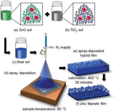
Fig. 1 shows a schematic representation of the multi-step process involved in producing Zn2TiO4 nanostructures via a template-assisted sol–gel route. The preparation routine begins with two sols obtained individually for ZnO and TiO2. This is represented in Fig. 1(a) and (b), respectively. For both cases, a required amount of the amphiphilic diblock copolymer, poly(styrene-block-ethylene oxide), P(S-b-EO) is dissolved in a solvent pair, one with good and the other with weak interactions with the blocks, in order to induce micro-phase separation leading to formation of micelles. The micelles in the solution are represented with red hydrophobic (PS) core and blue hydrophilic (PEO) corona in the insets of Fig. 1(a) and (b). The respective metal oxide precursors are then added to the individual solutions (depicted as green spheres for the ZnO sol and gray spheres for TiO2 sol), which selectively get incorporated in the hydrophilic part of the template and thereby react in a limited volume to initiate the formation of nanostructures in the system. In this fashion, the morphologies to be produced in the end are controlled and tuned as a function of the weight fraction of the solvents and the precursors added to the system. Finally, the two sols are mixed with a specific volume ratio to obtain a final sol as indicated in Fig. 1(c), which controls the morphology in the final system. To realize practical applications, the nanostructures are deposited in the form of solid films on the substrate by the spraying technique as shown in Fig. 1(d). Spray deposition is an industry-oriented approach towards preparation of films with an easy upscaling of the film thicknesses and final production volume.20 Combinations of different volumes of the ZnO and the TiO2 sols are sprayed in this study and are noted in Section S1 of the ESI† along with details about the spray protocol. In the course of this synthesis routine, it has been shown that the mixing ratio plays a crucial role to obtain the pure Zn2TiO4 phase which can only be synthesized in a narrow mixing regime for ZnO and TiO2 precursor concentrations (see Section S1 and S2†). After the spray deposition of the films, a final calcination step is required to impart crystallinity to the system. These steps are sketched in Fig. 1(e) and (f) (the SEM images of the calcined films produced from sols containing varied molar concentrations of the ZnO and the TiO2 precursors are given in Section S1†). Amongst the combinations of different volumes of ZnO and TiO2 sols, only the final sol containing molar ratio of ZnO precursor![[thin space (1/6-em)]](https://www.rsc.org/images/entities/char_2009.gif) :
:![[thin space (1/6-em)]](https://www.rsc.org/images/entities/char_2009.gif) TiO2 precursor of 1.05
TiO2 precursor of 1.05![[thin space (1/6-em)]](https://www.rsc.org/images/entities/char_2009.gif) :
:![[thin space (1/6-em)]](https://www.rsc.org/images/entities/char_2009.gif) 1, gives the pure Zn2TiO4 phase as characterized in the following.
1, gives the pure Zn2TiO4 phase as characterized in the following.
Experimental section
Materials and sol preparation
The amphiphilic diblock copolymer, poly(styrene-block-ethylene oxide), abbreviated as P(S-b-EO) [molar masses – 23 kg mol−1 for PS block; 7 kg mol−1 for PEO block; polydispersity index – 1.07] was used as received from Polymer Source Inc., Canada. Zinc acetate dihydrate [Zn(CH3COO)2·2H2O] 99.999% trace metals basis, with a density of 1.84 g mL−1 was purchased from Sigma Aldrich. Ethylene glycol-modified titanate [Ti(O2C2H4)2], with a density of 0.343 g mL−1 was synthesized using a procedure described in literature.21,22 As described below, two different sols, for ZnO and TiO2 were prepared separately containing equal volumes of [Zn(CH3COO)2·2H2O] and [Ti(O2C2H4)2], respectively. In order to achieve this, a specific weight fraction combination of the good solvent, the selective solvent and the precursor was chosen in each case. For the ZnO sol, N,N-dimethylformamide [C3H7NO], with a density of 0.95 g mL−1 was chosen as the good solvent, hence dissolving both the blocks of the diblock copolymer template. Water (density = 0.997 g mL−1) on the other hand only selectively dissolved the PEO block (for ZnO sol – wC3H7NO![[thin space (1/6-em)]](https://www.rsc.org/images/entities/char_2009.gif) :
:![[thin space (1/6-em)]](https://www.rsc.org/images/entities/char_2009.gif) wH2O
wH2O![[thin space (1/6-em)]](https://www.rsc.org/images/entities/char_2009.gif) :
:![[thin space (1/6-em)]](https://www.rsc.org/images/entities/char_2009.gif) wZn(CH3COO)2·2H2O = 0.92
wZn(CH3COO)2·2H2O = 0.92![[thin space (1/6-em)]](https://www.rsc.org/images/entities/char_2009.gif) :
:![[thin space (1/6-em)]](https://www.rsc.org/images/entities/char_2009.gif) 0.005
0.005![[thin space (1/6-em)]](https://www.rsc.org/images/entities/char_2009.gif) :
:![[thin space (1/6-em)]](https://www.rsc.org/images/entities/char_2009.gif) 0.075). For the TiO2 sol, C3H7NO was again used as the good solvent, whereas, hydrochloric acid (37% HCl), with a density of 1.2 g mL−1 served as the selective solvent (for TiO2 sol – wC3H7NO
0.075). For the TiO2 sol, C3H7NO was again used as the good solvent, whereas, hydrochloric acid (37% HCl), with a density of 1.2 g mL−1 served as the selective solvent (for TiO2 sol – wC3H7NO![[thin space (1/6-em)]](https://www.rsc.org/images/entities/char_2009.gif) :
:![[thin space (1/6-em)]](https://www.rsc.org/images/entities/char_2009.gif) wHCl
wHCl![[thin space (1/6-em)]](https://www.rsc.org/images/entities/char_2009.gif) :
:![[thin space (1/6-em)]](https://www.rsc.org/images/entities/char_2009.gif) wTi(O2C2H4)2 = 0.905
wTi(O2C2H4)2 = 0.905![[thin space (1/6-em)]](https://www.rsc.org/images/entities/char_2009.gif) :
:![[thin space (1/6-em)]](https://www.rsc.org/images/entities/char_2009.gif) 0.08125
0.08125![[thin space (1/6-em)]](https://www.rsc.org/images/entities/char_2009.gif) :
:![[thin space (1/6-em)]](https://www.rsc.org/images/entities/char_2009.gif) 0.01375).
0.01375).
Detailed synthesis of the zinc orthotitanate (Zn2TiO4) sol
To synthesize the principle compound, Zn2TiO4, ZnO and TiO2 sols were first prepared separately. For the preparation of 10 mL of the final (Zn2TiO4) sol, 2 mL of ZnO sol was mixed with 8 mL TiO2 sol.In order to prepare the ZnO sol, firstly, 30 mg of P(S-b-EO) was dissolved in 1 mL of C3H7NO by stirring at room temperature for 30 minutes. Secondly, 155 mg of Zn(CH3COO)2·2H2O was dissolved in 1 mL of C3H7NO in a separate glass vial also by stirring at room temperature for 30 minutes. Afterwards the polymer and the precursor solutions were filtered using Teflon filters with pore size of 0.45 μm into two separate glass vials, respectively. Next, 10.4 μL of deionized water was added to the polymer solution which was then again allowed to stir for 30 minutes at room temperature. Finally, the polymer solution (polymer + C3H7NO + deionized water) and the precursor solution (Zn(CH3COO)2·2H2O + C3H7NO) were mixed together with the aid of a syringe pump with a controlled mixing rate of the two solutions, as described in Section S1.1 of the ESI,† in order to obtain the final ZnO sol.
For preparation of the TiO2 sol, 120 mg of P(S-b-EO) was dissolved in 8 mL of C3H7NO by stirring the solution at room temperature for 30 minutes. Once a clear polymer solution was obtained, it was filtered into another glass vial using a Teflon filter (pore size – 0.45 μm). To this solution, 568.6 μL of HCl was added drop-wise followed by 115.45 mg of Ti(O2C2H4)2. The TiO2 precursor (Ti(O2C2H4)2) was added within 30 s after the addition of HCl to the polymer solution. This solution was then allowed to stir for 30 minutes at room temperature at the end of which a pale yellow turbid solution was obtained. After 30 minutes, the solution was heated to 90 °C and was stirred at this high temperature for 15 minutes until a pale yellow clear solution was obtained. This was then the final TiO2 sol, which stayed clear also at room temperature.
2 mL of the ZnO sol was then added to 8 mL of the TiO2 sol in a drop-wise manner (without a syringe pump) at room temperature, within 1 minute time. This solution was referred to as the final Zn2TiO4 sol.
Thin film and device preparation
The final zinc orthotitanate sol was then spray-deposited on a substrate at 80 °C for film preparation. The spray deposition as well as the post-treatment parameters are given in Section S1.2 of the ESI.†After the spray deposition, the films were sintered in a tube furnace, RETTH 230/3 provided by GERO Hochtemperaturofen GmbH at a heating ramp of 150 °C h−1 to 600 °C for 30 minutes. Only after this high temperature treatment at 600 °C of the spray-deposited film prepared using the final sol, the zinc orthotitanate (Zn2TiO4) compound was formed. The calcined films were then used for the fabrication of the final dye-sensitized solar cells (DSSCs). Details about the solar cell assembly and the materials involved are given in the ESI (Section S3†).
Characterization
The scanning electron microscopy (SEM) measurements on the samples were performed using a Zeiss Gemini NVision 40 apparatus. A constant accelerating voltage of 5 kV, a working distance of 3.5 mm and an aperture of 10 μm were maintained for all the measurements.X-ray diffraction measurements were performed at a Bruker D8 ADVANCE powder diffractometer. The data obtained were background subtracted using the program included in the DIFFRAC.SUITE provided by Bruker. A 2Θ range from 25–60° was probed using a copper anode X-ray source with wavelength λ = 1.54 Å operated at 40 kV and 40 mA. The theoretical peak positions for zinc oxide and zinc orthotitanate along with their relative intensities were obtained from Inorganic Crystal Structure Database (ICSD).
The UV/vis measurements were carried out in a Lambda 650S spectroscope, which provided UV (from deuterium lamp) and visible (from halogen lamp) wavelengths covering a range from 190 to 900 nm. The films were prepared on glass and were measured in transmission geometry. The 150 mm integrating sphere was used to register the scattered light from the sample before the signal was directed to the detector.
The current of the DSSC was measured for an applied voltage with a Keithly 2400 source meter in dark and under illumination. A solar simulator Solar Constant by K. H. Steuernagel Lichttechnik GmbH was used. The intensity was calibrated and set to 1000 W m−2 using a silicon-based calibration solar cell (WPVS Reference Solar Cell Typ RS-ID-3 by Fraunhofer ISE).
Results and discussion
Film morphology
Fig. 2(a) and (b) show SEM images of the calcined Zn2TiO4 nanostructures under low and high magnifications, respectively, obtained at the above-mentioned molar ratio of the ZnO and TiO2 precursors in the sol. Homogeneous foam-like morphology with inter-connected network is clearly observed. It has been successfully shown by Perlich et al. and Sacco et al. that sponge-like network morphologies for TiO2 and ZnO are highly beneficial for increased surface area, leading to high dye uptake and enhanced charge transport in photovoltaic devices.23,24 In the present work, a foam-like Zn2TiO4 nanostructured film is successfully obtained via a wet chemical synthesis route based on a template-assisted sol–gel approach. The porosity of this foam-like Zn2TiO4 film is extracted from the scattering length density profile of the film in the vertical direction (see Section S2.3 of the ESI†). A promising porosity of (52.5 ± 4.2)% is obtained for the foam-like film. The porosity of Zn2TiO4 film is slightly lower than that reported for pure ZnO foam-like films obtained from the same diblock copolymer template.25 This can be explained by the presence of two metal oxide precursors and the final composition of the sols used to prepare the film. The formation of the homogeneous foam-like morphology is also supported by the similar molar concentrations of Zn(CH3COO)2·2H2O and Ti(O2C2H4)2 in the respective sols. This leads to uniform mixing of the constituents resulting in the formation of a single compound phase. For dissimilar molar concentrations of Zn(CH3COO)2·2H2O and Ti(O2C2H4)2, final morphologies with large aggregates are produced and the formation of the desired foam-like morphology is hampered (see Section S1.3 of the ESI†). Hence, the importance of the molar concentrations of the metal oxide precursors in their individual sols is crucial in order to obtain a single phase with uniform film morphology, when the sols are mixed. This promising morphology, obtained after the calcination of the sprayed film, is further characterized in order to determine its crystallinity and optical properties. The nanostructured film is finally manifested as the active layer in a functional DSSC as described in the following.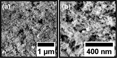 | ||
| Fig. 2 Scanning electron microscopy images of the spray-deposited foam-like zinc orthotitanate film under low (a) and high (b) magnifications. | ||
Crystallinity
Together with the composition of the sol, the impact of the calcination temperature on the formation of pure compound is also investigated. The spray-deposited film obtained from the sol containing molar concentration of Zn(CH3COO)2·2H2![[thin space (1/6-em)]](https://www.rsc.org/images/entities/char_2009.gif) :
:![[thin space (1/6-em)]](https://www.rsc.org/images/entities/char_2009.gif) Ti(O2C2H4)2 = 1.05
Ti(O2C2H4)2 = 1.05![[thin space (1/6-em)]](https://www.rsc.org/images/entities/char_2009.gif) :
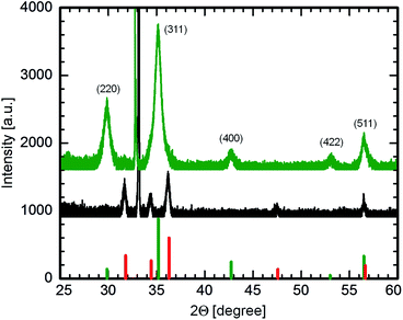
:![[thin space (1/6-em)]](https://www.rsc.org/images/entities/char_2009.gif) 1 is calcined at 400 and 600 °C. The X-ray diffraction (XRD) spectra of these films are plotted in Fig. 3. The XRD spectra are measured over a 2Θ range of 25–60°. The peaks obtained show a clear signature of the presence of a pure Zn2TiO4 phase3 when compared to the theoretical peak positions depicted by the green vertical lines, for the film calcined at 600 °C (green curve).
1 is calcined at 400 and 600 °C. The X-ray diffraction (XRD) spectra of these films are plotted in Fig. 3. The XRD spectra are measured over a 2Θ range of 25–60°. The peaks obtained show a clear signature of the presence of a pure Zn2TiO4 phase3 when compared to the theoretical peak positions depicted by the green vertical lines, for the film calcined at 600 °C (green curve).
The crystallite size for the film is calculated using the Scherrer's equation:26
 | (1) |
On the other hand, for the diffraction spectrum of the film calcined at 400 °C (black curve in Fig. 3), there is a clear absence of any signal corresponding to the Zn2TiO4 phase. The peaks however, match with the theoretical positions for the wurtzite phase of ZnO (indicated by the red vertical lines in Fig. 3). Therefore, it can be concluded that a high temperature of at least 600 °C is essential for the formation of Zn2TiO4 phase, in addition to the correct composition of the sol. This finding is in good agreement with the formation behavior of Zn2TiO4 phase, as established by Dulin and Rase via the melt-mixing method.27
Film composition
Energy dispersive X-ray spectroscopy (EDX) is performed on the samples synthesized from the sol with molar concentration of Zn(CH3COO)2·2H2![[thin space (1/6-em)]](https://www.rsc.org/images/entities/char_2009.gif) :
:![[thin space (1/6-em)]](https://www.rsc.org/images/entities/char_2009.gif) Ti(O2C2H4)2 = 1.05
Ti(O2C2H4)2 = 1.05![[thin space (1/6-em)]](https://www.rsc.org/images/entities/char_2009.gif) :
:![[thin space (1/6-em)]](https://www.rsc.org/images/entities/char_2009.gif) 1. The spray-deposited films are again calcined at 400 and 600 °C. The EDX spectra of the films are shown in Fig. 4(a) and (b).
1. The spray-deposited films are again calcined at 400 and 600 °C. The EDX spectra of the films are shown in Fig. 4(a) and (b).
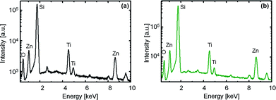 | ||
Fig. 4 EDX spectra obtained for spray-deposited films with molar concentration of Zn(CH3COO)2·2H2O![[thin space (1/6-em)]](https://www.rsc.org/images/entities/char_2009.gif) : :![[thin space (1/6-em)]](https://www.rsc.org/images/entities/char_2009.gif) Ti(O2C2H4)2 = 1.05 Ti(O2C2H4)2 = 1.05![[thin space (1/6-em)]](https://www.rsc.org/images/entities/char_2009.gif) : :![[thin space (1/6-em)]](https://www.rsc.org/images/entities/char_2009.gif) 1 after calcination at 400 °C (a) and 600 °C (b). 1 after calcination at 400 °C (a) and 600 °C (b). | ||
It is observed from the spectra that characteristic peaks of Ti, Zn and O are available for both samples. In addition, a strong Si peak contributed by the substrate is also present. This is a substantial evidence of the purity of the sample because other elements could not be detected. The composition of both samples obtained in terms of atomic percent is listed in Table 1. It is clearly stated from the results that a calcination temperature of 600 °C is essential in order to produce Zn2TiO4 as for this particular sample, the atomic % of Zn is nearly twice of that of Ti, which matches with the stoichiometric composition of the compound.
![[thin space (1/6-em)]](https://www.rsc.org/images/entities/char_2009.gif) :
:![[thin space (1/6-em)]](https://www.rsc.org/images/entities/char_2009.gif) Ti(O2C2H4)2 = 1.05
Ti(O2C2H4)2 = 1.05![[thin space (1/6-em)]](https://www.rsc.org/images/entities/char_2009.gif) :
:![[thin space (1/6-em)]](https://www.rsc.org/images/entities/char_2009.gif) 1, calcined at 400 °C and 600 °C
1, calcined at 400 °C and 600 °C
| Elements | Atomic % (400 °C) | Atomic % (600 °C) |
|---|---|---|
| Zn | 36.91 ± 0.77 | 40.40 ± 0.44 |
| Ti | 22.02 ± 0.25 | 20.79 ± 0.14 |
| O | 41.07 ± 0.26 | 38.81 ± 0.14 |
Optical properties
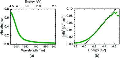
The optical properties of the Zn2TiO4 calcined (at 600 °C) film are tested by UV/vis spectroscopy. The absorbance data plotted in Fig. 5(a) shows that Zn2TiO4 also absorbs in the UV region like TiO2 and ZnO. In the literature, different band gaps for this compound have been recorded depending on the synthesis route, composition and theoretical techniques such as density functional theory used for the calculation of the same.17,28–30 In order to evaluate the band gap of the sample, Tauc's equation for direct band gap semiconductors31 is used as shown in eqn (2):| (αE)2 = A(E − Eg) | (2) |
Solar cell performance
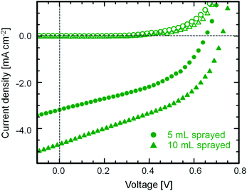
Using the optimized foam-like film morphology produced by spray deposition technique, preliminary tests have been performed with two different thicknesses of 4 and 10 μm of the active layer for the DSSC (details about the device assembly are given in Section S3†). The fabricated DSSC is measured under AM1.5 solar spectrum conditions providing a light intensity set to 1000 W m−2. The typical current density–voltage plots for the solar cells are shown in Fig. 6. The results from current–voltage characterization of active layers having different thicknesses are listed in Table 2. The increase in the short-circuit current density and open-circuit voltage with increasing film thickness of the active layer is clearly visible from the J–V curves. This can be related to extra charge carrier pathways generated in the system with increasing amount of material. On the other hand, the increase in the fill factor is really minor. The power conversion efficiency of 1.5% is however very promising as a preliminary result and is the best announced so far with Zn2TiO4 films synthesized via sol–gel technique. As a comparison, the device efficiency is comparable to that obtained for DSSCs fabricated from ZnO nanowires as the electron-conducting layer.34 Although optimizing the device efficiency was not the main focus in the present study, we believe, with certain modifications in the device fabrication protocol, such as incorporation of a blocking layer and a scattering layer5 will largely enhance the overall device performance and will be addressed in future work.Conclusions
In summary, a suitable solution-based approach is shown to successfully synthesize pure Zn2TiO4 phase. In addition, the so called sol–gel route is used in combination with a structure-directing diblock copolymer which allows for modifying and tuning the morphology and length scale of the nanostructures produced. The key to obtain a pure composite phase is therefore, individual synthesis of TiO2 and ZnO nanostructures followed by mixing them in a specific volume ratio rather than simultaneous synthesis of the Zn2TiO4 nanocomposite. Based on spray deposition method, homogeneous Zn2TiO4 films have been synthesized for applications in DSSCs. The requirement for high surface area of the active layer for intensified dye adsorption for applications in DSSCs35 is met by synthesizing the sponge-like network morphology of the film. Spray deposition is also shown to allow for an upscaling in the film thickness and thereby improving the final device performance. To the best of our knowledge, Zn2TiO4 DSSCs are reported for the first time in this article showing reasonable preliminary device performances. Hence, the present research sets a new landmark in the area of inorganic metal oxides and their compounds which have been increasingly sought for to develop new functional nanoscale devices. We postulate improvement in power conversion efficiency of Zn2TiO4 based DSSCs in near future with more optimized device fabrication procedure. Hence, the development of Zn2TiO4 as a new functional material parallel to conventional inorganic metal oxides in large-scale electro-optical applications is foreseen.Acknowledgements
P. Weiser and A. Holleitner are gratefully acknowledged for the possibility to perform SEM measurements. The authors are also thankful to K. Helm-Knapp and S. Geprägs for EDX measurements. This work was supported by TUM.solar in the frame of the Bavarian Collaborative Research Project “Solar technologies go Hybrid” (SolTec).Notes and references
- S. Chen, W. Xing, J. Duan, X. Hu and S. Z. Qiao, J. Mater. Chem. A, 2013, 1, 2941 CAS.
- Y.-J. Chang, E.-H. Kong, Y.-C. Park and H. M. Jang, J. Mater. Chem. A, 2013, 1, 9707 CAS.
- N. T. Nolan, M. K. Seery and S. C. Pillai, Chem. Mater., 2011, 23, 1496 CrossRef CAS.
- Q. Xu, M. Järn, M. Lindén and J.-H. Smått, Thin Solid Films, 2013, 531, 222 CrossRef CAS PubMed.
- X. Miao, K. Pan, Y. Liao, W. Zhou, Q. Pan, G. Tian and G. Wang, J. Mater. Chem. A, 2013, 1, 9853 CAS.
- D. Fu, X. L. Zhang, R. L. Barber and U. Bach, Adv. Mater., 2010, 22, 4270 CrossRef CAS PubMed.
- J. Burschka, N. Pellet, S.-J. Moon, R. Humphry-Baker, P. Gao, M. K. Nazeeruddin and M. Grätzel, Nature, 2013, 499, 316 CrossRef CAS PubMed.
- Q. Zhang, C. S. Dandeneau, X. Zhou and G. Cao, Adv. Mater., 2009, 21, 4087 CrossRef CAS PubMed.
- F. Zhuge, J. Qiu, X. Gao, X. Gan and W. Yu, Adv. Mater., 2011, 23, 1330 CrossRef CAS PubMed.
- J. A. Anta, E. Guillén and R. Tena-Zaera, J. Phys. Chem. C, 2012, 116, 11413 CAS.
- Z.-X. Chen, J. van der Eyden, W. Koot, R. van den Berg, J. van Mechelen and A. Derking, J. Am. Ceram. Soc., 1995, 17, 2993 CrossRef PubMed.
- G. Akgül, J. Mol. Struct., 2013, 1037, 35 CrossRef PubMed.
- S. K. Manik, P. Bose and S. K. Pradhan, Mater. Chem. Phys., 2003, 82, 837 CrossRef CAS PubMed.
- Z. Cai, J. Song, J. Li, F. Zhao, X. Luo and X. Tang, J. Sol-Gel Sci. Technol., 2012, 61, 49 CrossRef CAS.
- Y. Yang, X. W. Sun, B. K. Tay, J. X. Wang, Z. L. Dong and H. M. Fan, Adv. Mater., 2007, 19, 1839 CrossRef CAS PubMed.
- Z. Hong, M. Wei, Q. Deng, X. Ding, L. Jiang and K. Wei, Chem. Commun., 2010, 46, 740 RSC.
- Y.-S. Chang, Y.-H. Chang, I.-G. Chen, G.-J. Chen and Y.-L. Chai, J. Cryst. Growth, 2002, 243, 319 CrossRef CAS.
- Y.-J. Cheng and J. S. Gutmann, J. Am. Chem. Soc., 2006, 128, 4658 CrossRef CAS PubMed.
- K. Sarkar, M. Rawolle, E. M. Herzig, W. Wang, A. Buffet, S. V. Roth and P. Müller-Buschbaum, ChemSusChem, 2013, 6, 1414 CrossRef CAS PubMed.
- A. Abdellah, K. S. Virdi, R. Meier, M. Döblinger, P. Müller-Buschbaum, C. Scheu, P. Lugli and G. Scarpa, Adv. Funct. Mater., 2010, 22, 4078 CrossRef PubMed.
- R. Rossmanith, C. K. Weiss, J. Geserick, U. Hörmann, N. Hüsing, U. Kaiser and K. Landfester, Chem. Mater., 2008, 20, 5768 CrossRef CAS.
- X. Jiang, T. Herricks and Y. Xia, Adv. Mater., 2003, 15, 1205 CrossRef CAS PubMed.
- J. Perlich, G. Kaune, M. Memesa, J. S. Gutmann and P. Müller-Buschbaum, Philos. Trans. R. Soc., A, 2009, 367, 1783 CrossRef CAS PubMed.
- A. Sacco, A. Lamberti, R. Gazia, S. Bianco, D. Manfredi, N. Shahzad, F. Cappelluti, S. Ma and E. Tresso, Phys. Chem. Chem. Phys., 2012, 14, 16203 RSC.
- K. Sarkar, M. Rawolle, M. A. Niedermeier, W. Wang, E. M. Herzig, V. Körstgens, A. Buffet, S. V. Roth and P. Müller-Buschbaum, J. Appl. Crystallogr., 2014, 47, 76 CrossRef CAS.
- K. Hayat, M. A. Gondal, M. M. Khaled, S. Ahmed and A. M. Shemsi, Appl. Catal., A, 2010, 12920 Search PubMed.
- F. H. Dulin and D. E. Rase, J. Am. Ceram. Soc., 1960, 43, 125 CrossRef CAS PubMed.
- J. C. Conesa, Catal. Today, 2013, 208, 11 CrossRef CAS PubMed.
- S. A. Mayén-Hernández, G. Torres-Delgado, R. Castanedo-Pérez, M. G. Villarreal, A. Cruz-Orea, J. G. M. Alvarez and O. Zelaya-Angel, J. Mater. Sci.: Mater. Electron., 2007, 18, 1127 CrossRef.
- C. Wang, B.-Q. Xu, X. Wang and J. Zhao, J. Solid State Electrochem., 2005, 178, 3500 CrossRef CAS PubMed.
- J. Tauc, R. Grigorovici and A. Vancu, Phys. Status Solidi, 1966, 15, 627 CrossRef CAS PubMed.
- S. A. Mayén-Hernández, G. Torres-Delgado, R. Castanedo-Pérez, M. G. Villarreal, A. Cruz-Orea, J. G. M. Alvarez and O. Zelaya-Angel, J. Mater. Sci.: Mater. Electron., 2007, 18, 1127 CrossRef.
- C. Wang, B.-Q. Xu, X. Wang and J. Zhao, J. Solid State Chem., 2005, 178, 3500 CrossRef CAS PubMed.
- Q. Zhang, C. S. Dandeneau, X. Zhou and G. Cao, Adv. Mater., 2009, 21, 4087 CrossRef CAS PubMed.
- I. Gonzalez-Valls and M. Lira-Cantu, Proc. SPIE, 2012, 8471, 84710X CrossRef PubMed.
Footnote |
| † Electronic supplementary information (ESI) available. See DOI: 10.1039/c4ta02031f |
| This journal is © The Royal Society of Chemistry 2014 |

