 Open Access Article
 This Open Access Article is licensed under a
 Creative Commons Attribution 3.0 Unported Licence
Carbon flow electrodes for continuous operation of capacitive deionization and capacitive mixing energy generation†
S.
Porada
ab,
D.
Weingarth
b,
H. V. M.
Hamelers
a,
M.
Bryjak
c,
V.
Presser
*bd and
P. M.
Biesheuvel
ef
aWetsus, Centre of Excellence for Sustainable Water Technology, Oostergoweg 7, 8911 MA Leeuwarden, The Netherlands
bINM – Leibniz Institute for New Materials, Energy Materials Group, 66123 Saarbrücken, Germany. E-mail: volker.presser@inm-gmbh.de
cDepartment of Polymers and Carbon Materials, Faculty of Chemistry, Wroclaw University of Technology, Wybrzeze Wyspianskiego 27, 50-370 Wroclaw, Poland
dSaarland University, Campus D2 2, 66123 Saarbrücken, Germany
eLaboratory of Physical Chemistry and Colloid Science, Wageningen University, Dreijenplein 6, 6703 HB Wageningen, The Netherlands
fDepartment of Environmental Technology, Wageningen University, Bornse Weilanden 9, 6708 WG Wageningen, The Netherlands
First published on 22nd April 2014
Abstract
Capacitive technologies, such as capacitive deionization and energy harvesting based on mixing energy (“capmix” and “CO2 energy”), are characterized by intermittent operation: phases of ion electrosorption from the water are followed by system regeneration. From a system application point of view, continuous operation has many advantages, to optimize performance, to simplify system operation, and ultimately to lower costs. In our study, we investigate as a step towards second generation capacitive technologies the potential of continuous operation of capacitive deionization and energy harvesting devices, enabled by carbon flow electrodes using a suspension based on conventional activated carbon powders. We show how the water residence time and mass loading of carbon in the suspension influence system performance. The efficiency and kinetics of the continuous salt removal process can be improved by optimizing device operation, without using less common or highly elaborate novel materials. We demonstrate, for the first time, continuous energy generation via capacitive mixing technology using differences in water salinity, and differences in gas phase CO2 concentration. Using a novel design of cylindrical ion exchange membranes serving as flow channels, we continuously extract energy from available concentration differences that otherwise would remain unused. These results may contribute to establishing a sustainable energy strategy when implementing energy extraction for sources such as CO2-emissions from power plants based on fossil fuels.
1. Introduction
Human society continues to face an ever growing demand for renewable energy and affordable drinking water as a result of population growth and increased industrial and agricultural activity. In recent years, carbon-based materials have emerged as key components for many energy and water related technologies because of the high availability and abundance, vast structural and chemical variability, and moderate to low costs.1–3 In particular, high surface area porous carbons used for ion electrosorption have become a versatile and facile technology platform with applications ranging from highly efficient capacitive energy storage (electrical double-layer capacitors, EDLCs, also known as supercapacitors)1,4 and water treatment via capacitive deionization (CDI),2,5 to innovative and sustainable energy harvesting by capacitive mixing of aqueous solutions with different concentrations. Such concentration differences occur, for example, when river water mixes with seawater (a process called capmix)6 or are a result of the concentration differences of bicarbonate ions (HCO3−) dissolved in water from the exhaust gases of a power plant with high levels of CO2, versus the low carbon dioxide concentration in air.7Currently, all capacitive technologies employ intermittent cycling: ion electrosorption is followed by a regeneration step, and subsequent repeating of this discontinuous procedure. This operational mode has been employed in electrochemical capacitors,4 capacitive actuators,8 and CDI.2 CDI and capmix, until now, exclusively involve solid film electrodes2,9–27 integrated in an electrochemical cell that enables and facilitates electrolyte in- and out-flow. Yet, two major drawbacks are the discontinuous output, either in the form of desalinated water or produced energy, and the extra energy expenditure since ions have to travel twice across the ion exchange membrane interface, first in order to be adsorbed, and later to be released again to the spacer channel. In contrast, in a system based on flow electrodes, which operates in steady-state, the separated outflow streams have constant composition (unvarying in time), while ions only transfer across the membrane once. Instead of the discharge step taking place in the same cell, the carbon flow electrode suspensions can easily be regenerated outside the cell by directly mixing the two carbon particles streams together, which should lead to spontaneous discharge and salt release. The discharged particles must be separated from the resulting brine (in case of desalination) and (together with a portion of the feed water) re-injected in the electrode channels. Thus, a continuous energy harvesting/water deionization process would have the potential to achieve higher energy efficiency, more stable system performance, and ultimately enable a simpler system design than classical designs based on film electrodes.
Flow electrodes as the key element to enable continuous operation are based on capacitive carbon slurries. A carbon slurry is a suspension of charged carbon particles in an electrolyte and was first investigated by Micka in the 1960s28 and later by Kastening29–31 as a facile and robust technology to transport charge and electrosorbed ions held in the electrical double-layer, EDL, within the carbon particle. Unique features of carbon suspensions are that flowing suspensions are still electrically conductive and that the EDL persists when the carrier particles are moved mechanically, or in our case, flown within a suspension.32 In fact, from a fundamental point of view, the equilibrium electrosorption capacity of carbon materials should be identical for a flow or non-flow configuration.33 Having undergone a renaissance in recent years, flow electrodes have been proposed as breakthrough technologies to enable large scale energy storage and management34 and continuous CDI35 operation. However, many aspects of these technologies still remain unclear – especially in regards to energy harvesting applications.
The potential of the carbon flow electrodes has recently been demonstrated for CDI where flow electrodes have been introduced in two channels,35 both separated from the feed water spacer channel by electrically insulating ion exchange membranes that prevent mixing of the three streams at any time. As the carbon flow electrode can be circulated and regenerated continuously, intrinsic ion uptake capacity per carbon mass is no longer limiting system operation because the electrode flow channel size (when setting up the system) and flow rate (during operation) can be adjusted to meet the necessary requirements set by the application. Recently, an extension of this work was presented,36 and a membrane-free flow CDI concept37 proposed.
In our work, we exemplify the versatility and potential of flow electrodes by investigating flow CDI for water desalination and by expanding for the first time the application to capacitive energy harvesting. In detail, we employ membrane-based flow electrode cells for (1) continuous water desalination and (2) energy harvesting from capacitive mixing associated with CO2 emissions7,38,39 and from differences in water salinity.6,40–42 We present detailed data of the electrical conductivity of the carbon flow electrodes as function of carbon mass content. A novel flow channel design has been made possible by the development of hollow cylindrical ion exchange membranes that break with the paradigm of sandwich cell designs and unlock the full potential of capacitive carbon flow electrodes for environmental technologies.
2. Experimental section
2.1. Materials
Flow electrodes composed of a capacitive carbon suspension were prepared by mixing activated carbon powder (YP-50F, Kuraray Corp., Japan, SBET = 1450 m2 g−1, average pore size 1.01 nm, average particle size ∼10 μm; see ESI†) with either (1) deionized (DI) water, (2) simulated river water (17.1 mM NaCl) or a (3) 0.25 M monoethanolamine (MEA) solution (>99% reagent grade, Sigma-Aldrich). MEA was employed for energy harvesting because of the higher solubility of CO2 compared to pure water.43,44 After mixing, the suspensions were thoroughly de-aerated to remove residual oxygen trapped inside carbon pores.Viscosity analysis of the carbon flow electrodes was performed using a modular compact rheometer (Physica MCR 300, Austria) in a rotational concentric cylinder at room temperature. All measurements were performed using as an electrolyte 100 mM NaCl solution, or DI water.
Two types of ion-exchange membranes were employed: (1) commercially available flat plate anion and cation-exchange membranes (Neosepta AMX, δmem = 140 μm, and Neosepta CMX, δmem = 170 μm; Tokuyama, Japan), and (2) custom-made cylindrical ion-exchange membranes.45 Before being used for energy harvesting from capacitive mixing, both types of ion-exchange membranes were pretreated by soaking them for a few hours in a 0.25 M HCl solution for the cation exchange membrane (CEM) or in a 0.25 M KHCO3 solution for the anion exchange membrane (AEM). Cylindrical ion-exchange membranes were prepared by extrusion of the interpolymer poly(ethylene//styrene-co-divinylbenzene), PE//poly(St-co-DVB), and subsequent chemical modification, see ESI.†
2.2. System overview
Similar to Fig. 1A, the flow electrode capacitive deionization system (FCDI) consisted of one electrochemical charge/discharge cell (Fig. 1B), two continuously stirred tanks filled with the discharged carbon suspension, and one tank containing electrolyte solution. During water desalination, carbon particles were suspended in a saline solution of the same sodium chloride, NaCl, concentration as the water to be desalinated (e.g., 25 mM). During operation, the flow of carbon suspension through each of the flow electrode compartments is held constant at 2 mL min−1 and a defined voltage difference was applied to the cell using an electrochemical potentiostat (Iviumstat Standard, Ivium Technologies, The Netherlands) which also measures the electric current, I. As the electrical conductivity of the effluent of the middle desalination channel was continuously measured, it was possible to calculate the effluent salt concentration, and the salt removal rate. The latter was calculated from the difference between inflow and outflow salt concentration, multiplied by the water flow rate Φ, and divided by the area of one ion-exchange membrane.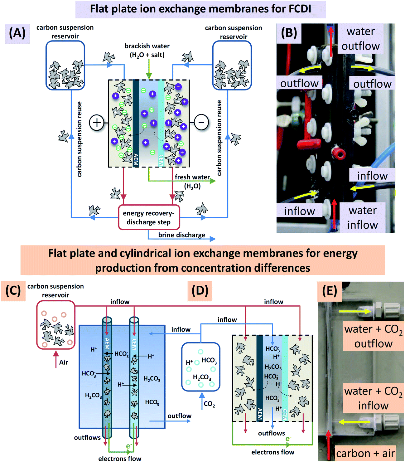 | ||
| Fig. 1 (A) Schematic view of a continuous system for flow-electrode CDI including a charging unit (salt adsorption; center of the figure), and a discharge unit (salt release), as well as the recirculation of the carbon suspension. Note that in the present work only the charging step is investigated, and energy recovery, discharge, and suspension reuse are not discussed. (B) Image of a single laboratory desalination cell (height 15 cm) including carbon suspension inflow and outflow tubes on the sides (yellow arrows), and water inflow and outflow, directed from bottom to top (red arrows). The electrical wires are connected via the circular front end connectors in red (left) and black (right). Schematic view of (C) cylindrical and (D) flat plate ion-exchange membranes used for continuous energy production from concentration differences. (E) Picture of continuous system utilizing cylindrical ion-exchange membranes for energy production. | ||
The flow electrode energy extraction system consisted of two storage tanks and a capacitive flow electrode cell to operate either with flat plate ion-exchange membranes or with novel cylindrically shaped membranes. Deionized water, simulated river water (17 mM NaCl), or a 0.25 M monoethanolamine (MEA) solution (>99% reagent grade, Sigma-Aldrich) was kept in one tank and flushed with CO2, while in the other tank, 10 wt% of porous carbon particles were suspended either in deionized water, seawater (600 mM of NaCl), or a 0.25 M MEA solution; these carbon suspensions were flushed with air. Note that the weight percentage of carbon in the suspension (wt%) is defined in this work as the mass of carbon divided by the mass of aqueous solution plus mass of carbon. During operation, the flow of carbon suspension through the cylindrically shaped membranes and electrolyte around the membranes were held constant at 1 mL min−1 and 2 mL min−1 respectively. Chronoamperometry at several different voltages was carried out and the current was recorded. Doing so, we obtained voltage-power-plots that are very suitable to characterize the electrical response of the system to different loads (cell voltage divided by current) and include the open-circuit voltage (second intersection with x-axis) and the voltage of maximum power extraction (maximum of the graph). It is interesting to note that for the FCDI system operating under steady-state conditions there is no fundamental difference between the types of charging, be it constant current or constant voltage, which in cyclic processes such as CDI or capmix are fundamentally different operational modes.2,26 Here in continuous operation, one value of cell voltage measured for the given system settings, defined by water flow rate, carbon mass fraction, and salt concentration, corresponds to a certain applied (or, generated) current output. Therefore, data representations as shown later fully define system behavior for a range of voltages and likewise for a range of currents.
2.3. Capacitive flow electrode cells
Electrochemical cells are the core element for charging and discharging carbon slurry-based flow systems. We used two types of capacitive flow cells using either (1) flat plate ion-exchange membranes, aplate = 36 cm2, see Fig. 1A, B, and D, or (2) novel cylindrical hollow ion-exchange membranes, acylindrical = 7.5 cm2, see Fig. 1C and E. The first cell type employs current collectors made from graphite plates with a rectangular cut-out with dimensions (12 × 3 × 0.3 cm3) and a CEM or an AEM placed one on each side of the cell on top of the current collector plates. For the saline feed water, a flow channel of width 3.2 mm (volume 11.4 mL) was created by placing two silicon gaskets in-between the two ion-exchange membranes, as seen in Fig. 1A. The carbon suspension entered the flow compartment via tubes inserted on the sides of the current collector while the saline water flow was directed from the bottom to the top through two nozzles located between the two silicon gaskets. The flow cell based on the cylindrical ion-exchange membranes, Fig. 1C and E, used as a current collector a thin platinum wire (diameter 250 μm) placed inside the core of the membranes. In this configuration, carbon suspension flow was directed through the core of the membranes, while the electrolyte solution was flowing around the membranes. All experiments were performed in single pass mode, meaning that the carbon slurry was not recycled. Particle discharge (such as depicted in Fig. 1A where a future fully continuous system is shown) and carbon suspension reuse was not investigated.A specialized flow cell was used to assess the electrical conductivity of a carbon flow electrode, see ESI Fig. S2.† This cell consisted of two titanium plates placed 4.4 mm apart, with each of the Ti electrodes having equal size (i.e., aplate = 5.6 cm2). This cell allowed us to study the influence of carbon content on the electrical conductivity during flow cell operation.
3. Results and discussion
3.1. Viscosity of carbon suspensions
All capacitive technologies in this study are based on flowable electrodes using carbon suspensions. Thus, the flowability and rheologic properties are important for device performance and system stability. In agreement with an earlier study on flow electrodes33 we see in Fig. 2 that with increased carbon mass loading, the suspension viscosity increases. Interestingly, we observe in Fig. 2 that the suspension viscosity is higher when using 100 mM of NaCl instead of DI water.46 This difference is enhanced when increasing the weight percentage of carbon. The full data sets of viscosity vs. shear rate are presented in ESI.† | ||
| Fig. 2 Carbon suspension viscosity versus carbon mass loading measured in 100 mM NaCl solution (red squares), and deionized water (black triangles). | ||
3.2. Flow electrode capacitive deionization
Flow electrode capacitive deionization (FCDI) was tested in the flat-plate design of Fig. 1A which is conceptually similar to the setup introduced by Jeon et al.35 For FCDI, the carbon loading in the flow electrode is an important parameter and, as expected, the amount of carbon strongly correlates with the salt removal rate as more carbon is available for fast ion electrosorption (Fig. 3A). This dependency on carbon content suggests that a large part of the total system internal resistance stems from the suspension in the electrode chambers, either for ions to reach the carbon particles (ionic resistance), or for the electrons to transfer from the current collectors to the particles. A higher carbon content of the flow electrode speeds up both processes because of shorter average distances for an ion to travel from membrane to the carbon particles, and because more particle–particle contacts enhance the effective electronic charge transfer. Indeed, to fully charge the carbon particles, each particle needs to be in contact at some point during the flow through the cell either with the current collector directly, or indirectly via another particle. The rapid increase in salt removal rate beyond 20 wt% carbon content illustrates the importance of particle–particle contacts to facilitate an effective percolation network for electron transport. Fig. 3A demonstrates that to increase the salt removal rate (at a given cell voltage), high carbon loadings are preferable. However, for a carbon loading beyond ∼20 wt%, the resulting suspensions were prone to clogging, and flow was easily disrupted as a result of the high viscosity (Fig. 2). The electrical conductivity of the flow electrode at various carbon loadings was measured, and correlated exactly with the salt removal rate, see Fig. 3A.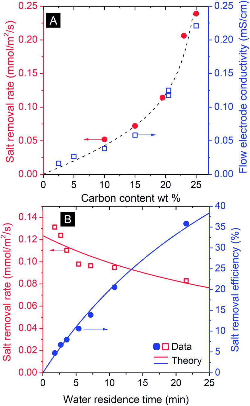 | ||
| Fig. 3 Influence of process parameters on operation of FCDI at constant cell voltage (csalt,in = 100 mM, Vcell = 1.2 V). (A) Influence of carbon content of the flow electrode, on salt removal rate (red dots τwater = 5.7 min) and flow electrode conductivity (blue squares). The dashed line serves to guide the eye. (B) Influence of water residence time τwater on salt removal rate (red squares) and efficiency (blue dots) measured for carbon flow electrode containing 20 wt% of activated carbon. Lines are based on the transport model discussed in the text. | ||
As for all flow systems, the water flow rate has an important effect on the overall performance. This is illustrated by the correlation between water residence time in the saline flow channel and the removal efficiency (Fig. 3B): with decreasing flow rate, thus increasing water residence time, τwater, the salt removal efficiency, which is defined as (1 − csalt,out(τ)/csalt,in) × 100%, increases. At the same time the removal rate, defined as a flux per unit membrane area, slightly decreases because with higher residence time the average salinity decreases which implies for a given voltage a lower current and thus lower salt removal rate.
The effect of residence time, τ, on the resulting salt removal efficiency of the FCDI cell, as seen in Fig. 3B, can be quantified by a simple plug-flow model for the spacer channel (direction z through the channel, 0 < z < L) based on Φdcsalt/dz = −JsaltA/L where Φ is the water flow rate in m3 s−1, Jsalt the salt removal rate (mol m−2 s−1), and A the membrane area in m2. Because the experiment is done at a constant cell voltage, Vcell, and assuming that the internal resistance is inversely proportional to csalt(z), the current density I (A m−2) must scale with csalt(z): I = αcsalt(z)Vcell where α is a specific system conductance (m Ω−1 mol−1). Assuming a constant value of the current efficiency λ, being the ratio of salt flux Jsalt over current density I (divided by Faraday's number F, thus λ = Jsalt/(I/F), to be discussed in more detail below), we can derive csalt(τ) = csalt,in exp(−(Vcellαλ/F/δ)τ), where the spacer channel thickness is δ = 3.2 mm, which fits the experimental data using α = 0.1 m Ω−1 mol−1 (λ ∼ 0.9 based on Fig. 4A), see Fig. 3B, while assuming a constant resistance R (= Vcell/I), independent of the salt concentration in the channel, does not fit the data.
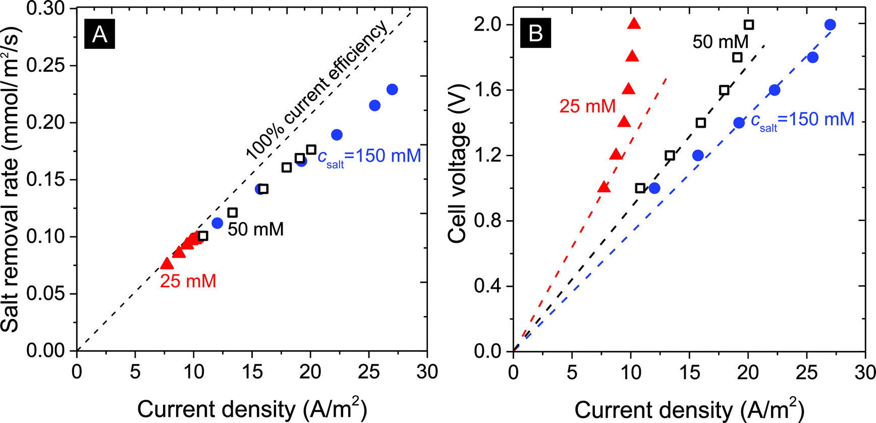 | ||
| Fig. 4 Influence of current density in A m−2 on (A) the salt removal rate, and (B) cell voltage (lines serve to guide the eye). | ||
The salt removal rate also depends on the feed water salt concentration. As seen in Fig. 4A and B, desalination of solutions at 25, 50, and 150 mM salt concentration was studied for various levels of the current density (expressed in Ampere per membrane area, A m−2). For all studied salinities we see a clear correlation between salt removal rate and applied current density. The ratio of the two fluxes (after dividing current by Faraday's number) is the current efficiency, and Fig. 4A shows how this ratio depends on current but not much on the salinity. The current efficiency decreases from an initial value close to 100% at a low current density of 7 A m−2 to approximately 85% beyond 25 A m−2.
Fig. 4B illustrates the correlation between the cell voltage and the measured current density: with increasing salinity, at the same cell voltage, higher current densities are obtained. For example, at csalt,in = 25 mM, an apparent limiting current density of ∼10 A m−2 is reached which increases to 20 and beyond 25 A m−2 for 50 mM and 150 mM salinity. Note that this limiting current is lower than a theoretical limiting current density from boundary layer analysis, calculated for 25 mM using Ilim = 2DcsaltF/Lbl, as ∼40 A m−2 (for Lbl = 200 μm, D = 1.7 × 10⁻⁹ m2 s−1) suggesting a mechanism different from the classic membrane-based limiting current. Indeed, the cell resistance (cell voltage divided by current, that is, the slope of the dashed lines) decreases with increasing salinity, as expected, but is far from being proportional to csalt, which classical theory would predict.47
3.3. Energy production from capacitive mixing using flow electrodes
Continuous cell operation is not only suitable for desalination, but also has potential for electricity generation via capacitive energy harvesting. To provide, for the first time, a proof-of-concept of using a flow electrode system for continuous energy harvesting from concentration differences, we utilized and compared six system configurations: (a) CO2 in water, (b) CO2 in MEA, and (c) salinity gradient experiments; for (1) a flat plate setup, versus (2) a flow electrode hollow cylindrical membrane cell.The operation of our continuous energy generation concept, measured in the flat plate setup, is presented in Fig. 5. Except for the initial phase of changing the cell voltage, stable power density is observed for each of the tested systems. This is contrary to conventional capacitive systems which require fixed carbon electrodes where water streams are switched alternatingly, in order to recover the initial salt adsorption capacity of the electrodes, see ref. 6 and 48. Such an intermittent operation is disadvantageous as it delivers a non-constant power output. With flow electrodes, the power output is constant in time, see Fig. 5.
 | ||
| Fig. 5 Power density versus time for three mixing energy systems using carbon flow electrodes. Lower red line: CO2 energy using water as electrolyte; middle green line: CO2 energy with 0.25 M MEA solution; upper blue line: salinity gradient energy using river water and seawater. | ||
The most facile way to illustrate the system performance for this technology is to use power density versus cell voltage plots (power plots) as provided in Fig. 6. Such plots provide a comprehensive summary of the behavior of the system at various levels of the external load. In between a cell voltage of zero and the open-circuit voltage (OCV), current is spontaneously generated and power is produced. Outside this range the process is not spontaneous: below Vcell = 0 V, we equalize concentrations of the two solutions faster than at short-circuit conditions, while for voltages higher than the OCV, the current direction is reversed and we actually enlarge the difference in ion concentration between the two flows. For each point on the curves in Fig. 6, the corresponding current I can be calculated by dividing power P by cell voltage Vcell: I = P/Vcell. The external load corresponding to that combination of current and voltage is given by Rext = Vcell/I. To describe the performance of the energy-generating systems, we can make the following analysis. The generated power is given by P = VcellI, where Vcell is the cell voltage (x-axis in Fig. 5), Vcell = OCV − Vint, and I the current. The current relates to the internal voltage drop in the cell, Vint, according to Vint = IRint where Rint is the internal cell resistance. These relations can be combined to P = Vcell/Rint(OCV − Vcell). The best fit using this parabolic relationship is plotted as dashed lines in Fig. 6 and are used to derive the values of Rint of the cell, see Table 1.
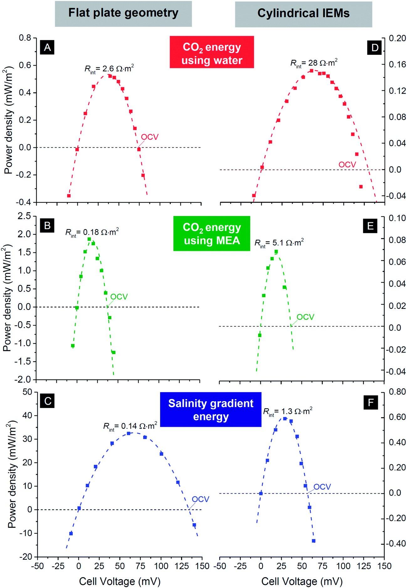 | ||
| Fig. 6 Power density versus cell voltage for three mixing energy systems using carbon flow electrodes operated in steady-state. First row, CO2 energy using water as electrolyte; middle row, CO2 energy with 0.25 M MEA solution; bottom row, salinity gradient energy using river water and seawater. Left column based on flat plate IEMs and corresponding cell design, see Fig. 1A; right column based on hollow cylindrical IEMs, see Fig. 1C and E. Dashed lines are best fits based on equation for power density vs. cell voltage. Derived values for the open circuit voltage (OCV) and internal resistance Rint given in Table 1. | ||
| Continuous operation (this work) | Intermittent operation (literature) | ||||
|---|---|---|---|---|---|
| Membrane design | Open circuit voltage (mV) | Maximum power density (mW m−2) | Internal resistance (Ω m2) | Power density (mW m−2) | |
| Flat plate IEMs | |||||
| CO2 | (A) | 74 | 0.52 | 2.6 | 0.56 (ref. 7) |
| CO2+ MEA | (B) | 37 | 1.9 | 0.18 | 9.0 (ref. 7) |
| Salinity gradient | (C) | 135 | 32 | 0.14 | 17 (ref. 48), 410 (ref. 49) |
| Cylindrical IEMs | |||||
| CO2 | (D) | 130 | 0.15 | 28 | — |
| CO2+ MEA | (E) | 37 | 0.068 | 5.1 | — |
| Salinity gradient | (F) | 57 | 0.59 | 1.3 | 82 (ref. 40) |
In Table 1 we compare values for the open circuit voltage and internal cell resistance for the three chemical systems and the two designs. From the data, several trends become evident: for the system using CO2, the open-circuit voltage is lower when MEA is added to the solution, compared to pure water. The system based on salinity gradients (i.e., river water versus seawater) has an overall lower resistance, and about a 10× higher maximum power density than for CO2 (for the given design). In general, for technologies based on cylindrical IEMs, the resistance is about two orders of magnitude higher than the values for the flat plate membranes, for all three systems. One obvious reason is the use of a single wire placed inside each hollow cylinder as current collector. Use of multiple wires should probably decrease the internal resistance for a design based on hollow cylindrical membranes.
4. Conclusions
Capacitive devices are emerging solutions for energy efficient water treatment which present novel ways to harvest mixing energy from naturally available concentration differences, and have the potential to impact on the fields of energy and water technology. In our paper we illustrate how transitioning from conventional fixed film electrodes to flow electrodes enables continuous operation and, for that reason, possibly leads to simpler and more stable system implementation and usage.In our study, we first evaluated and re-visited the novel idea of flow electrode CDI (FCDI) which was first introduced in 2013. We now have shown that several parameters are important when exploring FCDI, namely, water flow rate, and the carbon mass loading in the flow electrodes. Within the range of still flowable suspension loadings, we see that a higher loading yields better results in terms of power density and uptake kinetics. Furthermore the flow rate (residence time) is an important parameter to increase significantly the efficiency of the system, but very slow rates decrease the salt removal rate; thus optimized FCDI system engineering will require a careful balancing of cell design and operational parameters.
Energy harvesting, as shown by our data, can benefit from the use of flow electrodes because of constant operation. Though in our proof-of-principle experiments the power (and, implicitly, energy) density was lower than in a flat plate intermittent mode design, still, with intermittent operation yielding periods of energy generation followed by regeneration, continuous flow electrode systems have the perspective to be a competitive option. Tapping in energy sources by capacitive mixing techniques, such as from salinity or CO2 gradients, enables “green” extraction of energy from otherwise unused sources. Since power plants will continue to play a major role in the global energy production, especially energy extraction from CO2 emission sources can be an active and important contribution to sustainable energy policy for the next decades. Further work will draw a clearer picture on the performance of continuous system operation enabled by flow electrodes for capacitive technologies.
Acknowledgements
Part of this work was performed in the cooperation framework of Wetsus, centre of excellence for sustainable water technology (http://www.wetsus.nl). Wetsus is co-funded by the Dutch Ministry of Economic Affairs and Ministry of Infrastructure and Environment, the European Union Regional Development Fund, the Province of Fryslân, and the Northern Netherlands Provinces. SP acknowledges financial support of the Alexander von Humboldt Foundation. The INM is part of the Leibniz Research Alliance Energy Transition (LVE). VP acknowledges funding from the Hans Meier Leibniz Award of the German Research Council and thanks Prof. Eduard Arzt (INM) for his continuing support. Robert Drumm (INM) is thanked for his help with the viscosity measurements.Notes and references
- P. Simon and Y. Gogotsi, Nat. Mater., 2008, 7, 845–854 CrossRef CAS PubMed.
- S. Porada, R. Zhao, A. van der Wal, V. Presser and P. M. Biesheuvel, Prog. Mater. Sci., 2013, 58, 1388–1442 CrossRef CAS PubMed.
- C. Liu, F. Li, L.-P. Ma and H.-M. Cheng, Adv. Mater., 2010, 22, E28–E62 CrossRef CAS PubMed.
- F. Beguin, V. Presser, A. Balducci and E. Frackowiak, Adv. Mater., 2014, 26, 2219–2251 CrossRef CAS PubMed.
- P. M. Biesheuvel, S. Porada, M. Levi and M. Z. Bazant, J. Solid State Electrochem., 2014, 18, 1365–1376 CrossRef.
- D. Brogioli, Phys. Rev. Lett., 2009, 103, 058501 CrossRef.
- H. V. M. Hamelers, O. Schaetzle, J. M. Paz-García, P. M. Biesheuvel and C. J. N. Buisman, Environ. Sci. Technol. Lett., 2014, 1, 31–35 CAS.
- J. Torop, M. Arulepp, J. Leis, A. Punning, U. Johanson, V. Palmre and A. Aabloo, Materials, 2009, 3, 9–25 CrossRef PubMed.
- G. Wang, B. Qian, Q. Dong, J. Yang, Z. Zhao and J. Qiu, Sep. Purif. Technol., 2013, 103, 216–221 CrossRef CAS PubMed.
- E. Garcia-Quismondo, R. Gomez, F. Vaquero, A. L. Cudero, J. Palma and M. A. Anderson, Phys. Chem. Chem. Phys., 2013, 15, 7648–7656 RSC.
- S. Porada, L. Borchardt, M. Oschatz, M. Bryjak, J. Atchison, K. J. Keesman, S. Kaskel, M. Biesheuvel and V. Presser, Energy Environ. Sci., 2013, 6, 3700–3712 CAS.
- R. Zhao, M. van Soestbergen, H. H. M. Rijnaarts, A. van der Wal, M. Z. Bazant and P. M. Biesheuvel, J. Colloid Interface Sci., 2012, 384, 38–44 CrossRef CAS PubMed.
- K. Sharma, R. T. Mayes, J. O. Kiggans Jr, S. Yiacoumi, J. Gabitto, D. W. DePaoli, S. Dai and C. Tsouris, Sep. Purif. Technol., 2013, 116, 206–213 CrossRef CAS PubMed.
- T. Kim and J. Yoon, J. Electroanal. Chem., 2013, 704, 169–174 CrossRef CAS PubMed.
- C. Kim, J. Lee, S. Kim and J. Yoon, Desalination, 2014, 342, 70–74 CrossRef CAS PubMed.
- S. Porada, M. Bryjak, A. van der Wal and P. M. Biesheuvel, Electrochim. Acta, 2012, 75, 148–156 CrossRef CAS PubMed.
- L. Han, K. G. Karthikeyan, M. A. Anderson, K. Gregory, J. J. Wouters and A. Abdel-Wahab, Electrochim. Acta, 2013, 90, 573–581 CrossRef CAS PubMed.
- M. E. Suss, T. F. Baumann, W. L. Bourcier, C. M. Spadaccini, K. A. Rose, J. G. Santiago and M. Stadermann, Energy Environ. Sci., 2012, 5, 9511–9519 CAS.
- P. Liang, L. Yuan, X. Yang, S. Zhou and X. Huang, Water Res., 2013, 47, 2523–2530 CrossRef CAS PubMed.
- Y.-J. Kim, J.-H. Kim and J.-H. Choi, J. Membr. Sci., 2013, 429, 52–57 CrossRef CAS PubMed.
- J.-H. Yeo and J.-H. Choi, Desalination, 2013, 320, 10–16 CrossRef CAS PubMed.
- R. Zhao, S. Porada, P. M. Biesheuvel and A. van der Wal, Desalination, 2013, 330, 35–41 CrossRef CAS PubMed.
- R. Zhao, O. Satpradit, H. H. M. Rijnaarts, P. M. Biesheuvel and A. van der Wal, Water Res., 2013, 47, 1941–1952 CrossRef CAS PubMed.
- Y. A. C. Jande and W. S. Kim, Desalination, 2013, 329, 29–34 CrossRef CAS PubMed.
- P. Dlugolecki and A. van der Wal, Environ. Sci. Technol., 2013, 47, 4904–4910 CrossRef CAS PubMed.
- R. Zhao, P. M. Biesheuvel and A. Van der Wal, Energy Environ. Sci., 2012, 5, 9520–9527 CAS.
- E. Garcia-Quismondo, C. Santos, J. Lado, J. Palma and M. A. Anderson, Environ. Sci. Technol., 2013, 47, 11866–11872 CrossRef CAS PubMed.
- K. Micka, Chem. Listy, 1961, 55, 852–890 CAS.
- B. Kastening, W. Schiel and M. Henschel, J. Electroanal. Chem. Interfacial Electrochem., 1985, 191, 311–328 CrossRef CAS.
- B. Kastening and S. Spinzig, J. Electroanal. Chem. Interfacial Electrochem., 1986, 214, 295–302 CrossRef CAS.
- B. Kastening, T. Boinowitz and M. Heins, J. Appl. Electrochem., 1997, 27, 147–152 CrossRef CAS.
- E. Matijevic, Surface and Colloid Science, Springer, 1982 Search PubMed.
- V. Presser, C. R. Dennison, J. Campos, K. W. Knehr, E. C. Kumbur and Y. Gogotsi, Adv. Energy Mater., 2012, 2, 895–902 CrossRef CAS.
- J. W. Campos, M. Beidaghi, K. B. Hatzell, C. R. Dennison, B. Musci, V. Presser, E. C. Kumbur and Y. Gogotsi, Electrochim. Acta, 2013, 98, 123–130 CrossRef CAS PubMed.
- S.-I. Jeon, H.-R. Park, J.-G. Yeo, S. Yang, C. H. Cho, M. H. Han and D.-K. Kim, Energy Environ. Sci., 2013, 6, 1471–1475 CAS.
- S.-I. Jeon, J.-S. Park, J.-G. Yeo, S. Yang, J. Choi and D. K. Kim, J. Mater. Chem. A, 2014, 2, 6378–6383 CAS.
- K. B. Hatzell, E. Iwama, A. Ferris, B. Daffos, K. Urita, T. Tzedakis, F. Chauvet, P.-L. Taberna, Y. Gogotsi and P. Simon, Electrochem. Commun., 2014, 43, 18–21 CrossRef PubMed.
- J. M. Paz-Garcia, O. Schaetzle, P. M. Biesheuvel and H. V. M. Hamelers, J. Colloid Interface Sci., 2014, 418, 200–207 CrossRef CAS PubMed.
- M. Gellender, J. Renewable Sustainable Energy, 2010, 2, 023101 CrossRef PubMed.
- B. B. Sales, O. S. Burheim, F. Liu, O. Schaetzle, C. J. N. Buisman and H. V. M. Hamelers, Environ. Sci. Technol., 2012, 46, 12203–12208 CrossRef CAS PubMed.
- R. A. Rica, R. Ziano, D. Salerno, F. Mantegazza, M. Z. Bazant and D. Brogioli, Electrochim. Acta, 2013, 92, 304–314 CrossRef CAS PubMed.
- R. A. Rica, R. Ziano, D. Salerno, F. Mantegazza and D. Brogioli, Phys. Rev. Lett., 2012, 109, 156103 CrossRef CAS.
- M. R. M. Abu-Zahra, J. P. M. Niederer, P. H. M. Feron and G. F. Versteeg, Int. J. Greenhouse Gas Control, 2007, 1, 135–142 CrossRef CAS.
- G. T. Rochelle, Science, 2009, 325, 1652–1654 CrossRef CAS PubMed.
- A. H. Galama, J. W. Post, M. A. Cohen Stuart and P. M. Biesheuvel, J. Membr. Sci., 2013, 442, 131–139 CrossRef CAS PubMed.
- Y. C. Wu, J. Phys. Chem., 1968, 72, 2663–2665 CrossRef CAS.
- M. B. Andersen, M. van Soestbergen, A. Mani, H. Bruus, P. M. Biesheuvel and M. Z. Bazant, Phys. Rev. Lett., 2012, 109, 108301 CrossRef CAS.
- B. B. Sales, F. Liu, O. Schaetzle, C. J. N. Buisman and H. V. M. Hamelers, Electrochim. Acta, 2012, 86, 298–304 CrossRef CAS PubMed.
- F. Liu, O. Schaetzle, B. B. Sales, M. Saakes, C. J. N. Buisman and H. V. M. Hamelers, Energy Environ. Sci., 2012, 5, 8642–8650 CAS.
Footnote |
| † Electronic supplementary information (ESI) available. See DOI: 10.1039/c4ta01783h |
| This journal is © The Royal Society of Chemistry 2014 |