 Open Access Article
 This Open Access Article is licensed under a Creative Commons Attribution-Non Commercial 3.0 Unported Licence
Compressed hydrogen gas-induced synthesis of Au–Pt core–shell nanoparticle chains towards high-performance catalysts for Li–O2 batteries†
Cheng Chao
Li‡
a,
Wenyu
Zhang‡
ac,
Huixiang
Ang
a,
Hong
Yu
ac,
Bao Yu
Xia
b,
Xin
Wang
b,
Yan Hui
Yang
b,
Yang
Zhao
a,
Huey Hoon
Hng
*a and
Qingyu
Yan
*acd
aSchool of Materials Science and Engineering, Nanyang Technological University, 639798, Singapore. E-mail: ashhhng@ntu.edu.sg; alexyan@ntu.edu.sg; Fax: +65 6790 9081; Tel: +65 6790 4583
bSchool of Chemical and Biomedical Engineering, Nanyang Technological University, 637457, Singapore
cTUM CREATE Research Centre@NTU, Nanyang Technological University, 637459, Singapore
dEnergy Research Institute@NTU, Nanyang Technological University, 637553, Singapore
First published on 8th May 2014
Abstract
Herein we reported a green synthetic route for the preparation of Au–Pt core–shell nanoparticle chains in a two-step route without the use of any surfactants. In the synthesis, compressed hydrogen was used as a reducing reagent, which also promoted the assembly of particle chains. The as-prepared monodispersed gold nanoparticles were manipulated by dipoles to form chain-like nanostructures under high pressure; meanwhile, in situ epitaxial growth of Pt shell on gold nanochains occurred, leading to the formation of Au–Pt core–shell nanoparticle chains. The resulting bimetallic Au–Pt core–shell chains showed excellent catalytic activity as cathodes in lithium oxygen batteries with a low charge–discharge over potential and outstanding cycle performance because of its clean catalytic surface, interconnected nanostructure, which provided a good electron path and innate synergistic effect.
Introduction
As one of the important energy conversion technologies, rechargeable Li–oxygen batteries have attracted significant interest because they have a much higher gravimetric energy storage density compared with all other chemical batteries and are compatible with gasoline.1–6 In addition, Li–oxygen batteries are also eco-friendly electrochemical power sources because they use oxygen from the environment as the cathode material. However, the practical use of Li–O2 batteries is still limited by several serious drawbacks such as high charge–discharge over-potential, low rate capability, and poor cycling stability.7–10 It is generally considered that the key factor for improving the electrochemical performance of Li–O2 batteries is to find effective cathode catalysts to promote the oxygen reduction (ORR) and oxygen evolution reactions (OER).11–14 To this end, tremendous efforts have been devoted to explore various cathode catalysts for addressing the abovementioned challenges.15–18 In particular, bifunctional catalysts such as Fe–N–C,19 transition bimetallic nitrides,20 α-MnO2/Pd,21 porous carbon or two-dimensional (2D) graphene nanosheet (GNS)-supported transition metal oxides22 have also received great interest due to their favorable ORR and OER activities. Shao-Horn and co-workers reported a new bifunctional Pt–Au alloy catalyst for rechargeable Li–oxygen batteries using a carbonate electrolyte.23 The new bifunctional Pt–Au electrocatalysts significantly decreased the overvoltage, especially for the charge process. However, the Pt–Au electrocatalyst based cells suffer from the severe degradation of carbonate electrolytes.24 Although ether solvents have been demonstrated as an effective alternative for carbonate-based electrolytes and much progress has been achieved, exploring novel bifunctional electrocatalysts to upgrade the performance of Li–O2 cells still remains a significant challenge.As we know, the size, morphology and composition of catalyst particles on the nanometer scale profoundly affect their reaction performance. Nanoscale catalyst particles with a large specific surface area would lead to an abundance of active sites involved in catalytic reactions.25–29 In particular, control over the catalyst particle morphology allows for selective exposure of a larger fraction of reactive facets on which the active sites can be enriched and tuned. Recent theoretical calculation based on first principles have demonstrated that the activity of ORR/OER catalysts is also greatly dependent on the electron transfer efficiency.30 Sufficient electron participation can quickly reduce the adsorbed oxygen molecules to OH− without any barrier through an efficient 4e− pathway.30 Compared to separated metal nanoparticle catalysts, the interconnected metal nanoparticles, e.g. chains, would have better electron transfer efficiency. Therefore, it is highly desirable but challenging to develop a synthetic route for precious metal-based bifunctional catalysts with an interconnected structure and a clean catalytic surface.
In this study, we report a green synthetic process for the preparation of Au–Pt core–shell nanoparticle chains by the integration of electrical dipole-induced self-assembly and the simultaneous epitaxial growth of the Pt shell. Compressed hydrogen acted as a clean reducing reagent in the synthesis, which also helped in the assembly of the nanoparticles. As expected, the obtained bimetallic Au–Pt core–shell nanoparticle chains showed excellent catalytic activity and stability as cathodes in non-aqueous lithium oxygen batteries due to their clean catalytic surface and interconnected nanostructure. At a current density of 200 mA g−1, the fabricated Li–O2 cell operating with an ether-based electrolyte exhibited a discharging voltage of ∼2.7 V and a charging voltage of 4.0 V for 20 cycles.
Results and discussion
The schematic for the compressed hydrogen gas-induced self-assembly and growth method for the preparation of Au–Pt core–shell nanoparticle chains is shown in Fig. 1. The advantage of this method for preparing core–shell nanomaterials is that the shell thickness/coverage can be easily controlled by simply adjusting the dosage of second metal ions (Pt) to Au seeds in solution. At a lower concentration of H2PtCl4, Pt0 can be only deposited on the Au core to form monodispersed Au–Pt core–shell nanoparticles by heterogeneous nucleation growth. Further increase in the concentration of H2PtCl4 will allow more Pt0 to deposit on the Au core and connect the neighbouring Au nanoparticles to form chains. Recently, various routes, involving surfactant-based templates,32 molecular recognition,33 specific functionalization,34 surface- or solvent-induced phase separation35 and magnetic dipoles,36 have been developed to assemble pre-synthesized metallic nanoparticles into one-dimensional chains and networks that have potential applications in sub-wavelength optical and thermal devices. In this work, compressed hydrogen is used as the driving force for producing such elegant assembled nanochain networks by unbalancing the attractive van der Waals potentials and residual electrostatic repulsions and increasing the chance of Brownian collisions. The calculated energy for dipole attraction between nanoparticles can be as high as 10 kJ mol−1 based on the classical formula .37 Without the use of pressure, the gold nanoparticles system is relatively stable because of the surface charge induced electrostatic repulsions, which counteract the attractive van der Waals and hydrogen bonding potentials. However, when a high pressure (∼250–500 psi) is introduced into the reactor, the hydrogen-expanded aqueous solution reduces the solvating ability of sodium citrate. Partial loss of the surface-adsorbed charged citrate ions reduces the electrostatic repulsions between the particles. The nanoparticles under the influence of serendipitous Brownian collisions and attractive van der Waals force may start to form close contacts. Then, the dipole–dipole interactions then trigger the formation of linear chains of single nanoparticles to minimize the enthalpy of the system by promoting dipole alignment and reducing the inter-dipole distance. Simultaneously, Pt precursor PtCl42− could be reduced by compressed hydrogen gas and slowly deposit on the interconnected gold nanoparticles, resulting in the final Au–Pt core–shell nanoparticle chains.
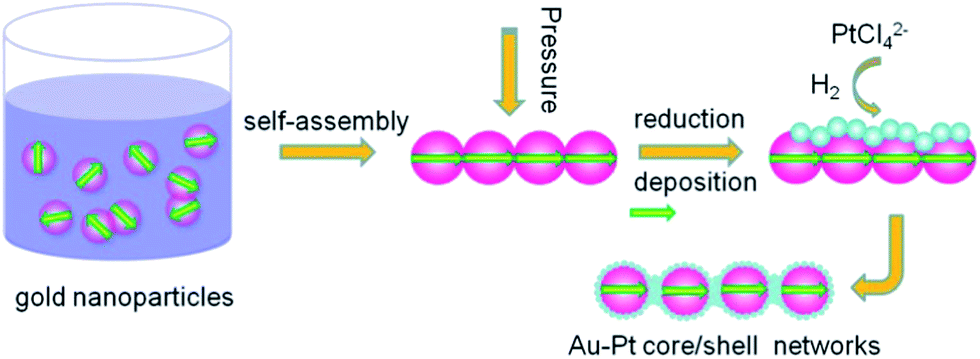 | ||
| Fig. 1 The schematic model diagram for Au–Pt core–shell nanoparticle chains; the arrows denote the electrical dipoles. The Pt shell is thin and highly porous. | ||
Fig. 2 shows the X-ray diffraction (XRD) pattern of the as-prepared samples. Two sets of diffraction peaks are clearly observed, which can be indexed to the (111), (200), and (220) reflections of the face-centered cubic Pt (JCPDS #04-0802) and Au (JCPDS #04-0784), respectively. All diffraction peaks are broadened, indicating nanoscale crystal domain size. The peak splitting of the Au and Pt phase suggests that the product is a heterogeneous phase but a solid solution, which is in agreement with the previously reported powder diffraction results.23,38
 | ||
| Fig. 2 XRD pattern of Au–Pt core–shell nanoparticle chains. | ||
Transmission electron microscopy (TEM) was further used to characterize the morphology and the detailed structure of the products. Fig. 3a is the TEM image of gold nanoparticles prepared by the sodium citrate reduction. It can be seen that the gold nanoparticles are monodispersed with an average particle size of 15 nm. Following the hydrogen induced reduction process in the presence of H2PtCl4 precursor, chain-like products were obtained (Fig. 3b and c). As can be seen in the TEM image, the nanoparticles are connected to one another and form a linear assembly with observable sub branches. It should be noted that there are no gaps between the adjacent nanoparticles (Fig. 3d and e), which is quite different from previously reported metal nanoparticle chains governed by electrostatic force, surfactants and magnetic forces.39–41 The high-resolution TEM image (Fig. 3f) indicates that the gold nanoparticles were linked and coated by thin Pt shells to form a bean pod-like structure. The observed lattice spacing of 2.30 Å corresponds to the (111) facet of face-centered cubic (fcc) Pt. The core–shell structure was confirmed by electron energy-loss spectrum (EELS) mapping analysis. Fig. S1† shows the EELS mapped images of Au–Pt nanoparticles, in which Au and Pt are color-coded as green and red, respectively. Au is present only in the core region of each nanoparticle, and Pt is present only on the shell.
 | ||
| Fig. 3 Representative TEM images of (a) gold nanoparticles, (b and c) Au–Pt core–shell nanoparticle chains, (d) a single Au–Pt nanochain. (e and f) HRTEM images of the Au–Pt core–shell nanochain. (g) EDX spectrum of Au–Pt core–shell nanoparticle chains. | ||
The line-scanned EELS data of a single nanoparticle (Fig. S1†) further confirmed the core–shell structure showing Au on the inside and Pt on the outside. The energy dispersive X-ray spectrometry (EDX) was performed on a random selected area of the sample, which showed that the Au and Pt core–shell network-like products are composed only of gold and platinum (Fig. 3g). The contents of Au and Pt are 56.14 at% and 43.86 at%, respectively, which is close to that of the precursor solution.
Fig. 4 shows the cyclic voltammetry (CV) profiles of the as-prepared Au–Pt core–shell in 0.5 M H2SO4 electrolyte. As shown in Fig. 4, there are well-defined hydrogen desorption/adsorption peaks between −0.24 V and 0.2 V, and Pt oxidation/reduction peaks are in the range of 0.2–1.0 V. The electrochemically active surface areas (ECSA) were calculated by measuring the Coulombic charge of hydrogen adsorption and assuming a value of 210 μC cm−2 for the adsorption of a hydrogen monolayer. The ECSA was calculated to be 25.8 m2 g−1. The lower ECSA for the Au–Pt core–shell nanoparticle chain catalyst compared with the Pt nanoparticles in commercial catalysts (ECSA, 51.0 m2 g−1), is most likely due to its larger size. The oxygen reduction reaction (ORR) activity of the Au–Pt core–shell nanoparticle chains was investigated using the rotating-disk electrode (RDE) technique at a scan rate of 10 mV s−1 (Fig. 5a). From the RDE curves, the ORR current densities exhibited an increase with increasing rotation speed, indicating that it is a diffusion controlled process. The current densities at 0.40 V are 4.6 mA cm−2 and the half-wave potential of the Au–Pt core–shell nanoparticle chains is 0.825 V at a rotation speed of 1600 rpm. Obviously, the activity is much better than that of a commercial Pt/C catalyst (0.818 V). The RDE polarization curves of oxygen reduction recorded at different rotation speeds (400 to 2500 rpm) were also analyzed using the Koutecky–Levich (K–L) equation (Fig. 5b).42

 | ||
| Fig. 4 Cyclic voltammetric curves of Au–Pt core–shell nanoparticle chains recorded in 0.5 M H2SO4 solution at different scan rates. | ||
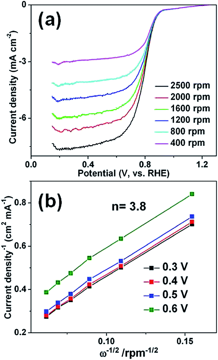 | ||
| Fig. 5 (a) Linear sweep voltammetry curves of ORR at various rotation rates for Au–Pt core–shell nanoparticle chains modified electrode. (b) Koutecky–Levich plots of Au–Pt core–shell nanoparticle chains electrode derived from RDE voltammograms in (a) at different electrode potentials. | ||
To investigate the electrochemical performance, Li–oxygen batteries with a non-aqueous electrolyte were fabricated. Our Li–O2 cell was assembled with modified Swagelok configurations,43 in which Li foils are used as the reference and counter electrodes and a stainless steel net supported Au–Pt/C as the working electrodes. The specific discharge–charge capacities are limited to 1000 mA h g−1. Typical charge and discharge voltage profiles of the Li–O2 cell are shown in Fig. 6a. At a current density of 50 mA g−1 based on the total mass of the Au–Pt core–shell network-carbon hybrid material, the average discharging voltage was about 2.82 V, close to the thermodynamic potential of the reaction 2Li+ + 2e− + O2 → Li2O2, while the average charging voltage was about 3.77 V, which is 0.82 V higher than the discharging voltage. This overpotential was much lower than those of other reported catalysts such as graphene,44 transition metal oxides,45 perovskite oxides,16 MoN–graphene8 and mesoporous pyrochlore.46 The overpotential slightly increased with increasing current densities (Fig. 6a) but the charging potential at 100 and 200 mA g−1 was still <4.0 V. The round-trip efficiencies (the discharging specific energies–charging specific energies) of the as-prepared Au–Pt core–shell nanoparticle chain electrode (Fig. 6a) at current densities of 50, 100 and 200 mA g−1 are calculated to be 78.3%, 67.0%, and 57.1%, respectively. These values are also much improved in comparison to pure carbon cathode and previously reported graphene materials.42 To demonstrate the merits of the core–shell chain, the lithium oxygen performances based on other Au and Pt nanostructures was also evaluated. Clearly, the Au–Pt core–shell chains electrodes exhibit lower charge and discharge potential in comparison with monodispersed Au–Pt core–shell nanoparticles and a mixture of Au Pt nanoparticles (Fig. S3 and S4†). Furthermore, the Au–Pt core–shell network electrodes also exhibit good cycling stability. The cycle life of the Li–O2 cell was tested with a capacity cut-off of 1000 mA h g−1 at a current density of 200 mA g−1. The cell showed good cycling ability for over 20 cycles in dry oxygen (Fig. 6c). During cycling, the final voltage of each discharging segment was stabilized at 2.6–2.7 V, and the final voltage of each charging segment was in the range of 4.0 to 4.1 V (Fig. 6b and c). The good cycling performance of the Au–Pt core–shell network electrode can be attributed to the interconnected bimetal nanostructures, which greatly increase the electron transport in the electrocatalysts compared to the separated precious metal nanoparticles (Fig. S5†). In particular, the bimetallic catalysts not only inherit the catalytic properties of each component, but also have higher catalytic efficiencies than their monometallic counterparts because of a strong synergy between the metals. The origin of this synergy between two metals is generally ascribed to electronic (ligand) and geometric (ensemble) effects. In the gold bimetallic catalysts, because gold has the highest electronegativity (2.54), the electron transfer from the second metal to gold may occur, which will affect the catalytic performance of gold by electronic modification. In addition, the synthesis route eliminates the use of strong coordinated surfactants, which results in a clean catalytic surface.
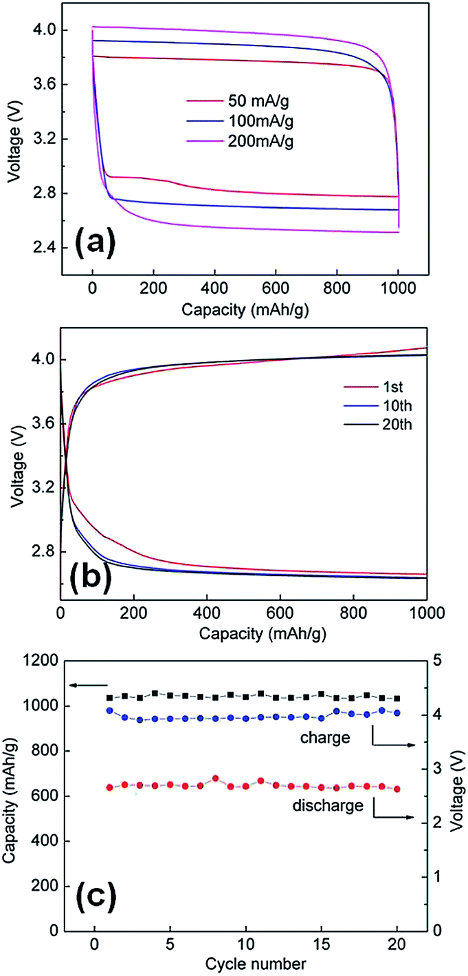 | ||
| Fig. 6 (a) Charging and discharging voltage profiles of the cell at various current densities. (b) Charging and discharging voltage profiles of the cell at 200 mA g−1. (c) Specific discharge capacity of the cell over 20 cycles at 200 mA g−1 (black) and cell voltage upon completion of each discharge (red) and charge (blue) segment over 20 cycles. | ||
Conclusions
A green synthetic process was developed to prepare bifunctional Au–Pt core–shell nanoparticle chain electrocatalysts using high pressure hydrogen gas as the self-assembly inducing reagent and reducing reagent. In the synthesis, surfactants were not used and the electrical dipoles are believed to be the driving force for producing such elegant assembled nanochain networks. Due to its clean catalytic surface and improved electron transfer efficiency, the obtained bimetallic Au–Pt core–shell nanoparticle chains showed excellent catalytic activity as cathodes in lithium oxygen batteries with a low charge–discharge over potential and outstanding cycle performance of the interconnected nanostructure.Experimental
Synthesis of gold nanoparticles
The gold nanoparticles were synthesized according to the route reported previously with minor modifications.31 Typically, 1.67 mL of 30 mM HAuCl4 aqueous solution was added rapidly to a solution of 4 mM sodium citrate (50 mL) that was heated under reflux. Heating under reflux was continued for an additional 15 min during which the colour changed to deep red. The obtained gold nanoparticles suspension was automatically cooled down to room temperature and stored for further use.Synthesis of Au–Pt core–shell nanoparticle chains
0.5 mL of 30 mM H2PtCl4 was added into 20 mL gold nanoparticles suspension under vigorous stirring. The mixture was then transferred into a Parr reactor with a volume of 30 mL. The reactor was first purged with hydrogen gas for three times to remove air. Compressed hydrogen gas was then introduced into the reactor (the pressure can be controlled by regulator). The reaction system was maintained at room temperature for 24 h. After that, the hydrogen was released and the black product was collected by centrifugation and washed with deionized water and absolute ethanol several times, which was followed by freeze drying.Electrocatalytic activity measurement
The electrocatalytic activities of the samples were measured using a conventional three-electrode cell with an Autolab potentiostat/galvanostat (Model PGSTAT-72637, Brinkman Instruments). The three-electrode cell consisted of a Pt wire serving as the counter electrode, a saturated calomel electrode (SCE) serving as the reference electrode, and a glassy carbon (GC) disk (5 mm in diameter) coated with catalysts, serving as the working electrode. To fabricate a working electrode, 5 mg of catalyst powder was dispersed in a diluted Nafion solution, which was then ultrasonicated for 30 min to form a homogeneous black suspension. Then, 10 μL of the resulting suspension was carefully pipetted onto the surface of the GC electrode, and the coating was dried at room temperature for 12 h.Electrochemical testing of Li–O2 cells
The oxygen electrodes were prepared as follows: a catalyst slurry was prepared by mixing the as-prepared Au–Pt catalyst (40 wt%), super P (40%) and polyvinylidene fluoride (PVDF) (20 wt%) in N-methyl-2-pyrrolidone (NMP). The mixture was then coated on a glass fiber separator, which was punched into discs with a diameter of 14 mm and dried at 80 °C in a vacuum oven for 12 h. The typical loading of the air electrode is about 1 mg cm−2. The Li–O2 cells were assembled in an Ar filled glove box with water and oxygen levels of less than 0.1 ppm. A lithium foil was used as the anode and was separated by a glass microfibre filter soaked in 1 M LiCF3SO3 with tetra(ethylene) glycol dimethyl ether (TEGDME) as the electrolyte. Li–O2 cells were assembled in the following order:23 (1) placing a lithium foil onto the bottom of a stainless steel cell, which is used as the current collector, (2) adding 0.2 mL electrolyte, (3) placing a piece of the separator onto the lithium foil, (4) adding more electrolyte, (5) placing the cathode-coated separator onto the separator, (6) adding on top a cathode current collector and (7) purging the cell with pure oxygen for 2 minutes. The cell was gas-tight except for the stainless steel mesh window, which exposed the porous cathode film to the oxygen atmosphere. All the measurements were conducted in 1 atm dry oxygen atmosphere to avoid any negative effects of humidity and CO2. Galvanostatic discharge–charge measurements were conducted using a Neware battery testing system. The specific capacity was calculated based on the mass of Super-P carbon black in the cathode electrodes.Characterization
The crystallographic phases of the prepared products were investigated by X-ray power diffraction method (XRD) using a Shimadzu XRD-6000 with Cu Kα radiation. The morphologies of the as-prepared sample were characterized by field-emission scanning electron microscopy (FESEM; JSM-6700F), transmission electron microscopy (TEM; JEM-2010, 200 kV), selected area electron diffraction (SAED), and high-resolution transmission electron microscopy (HRTEM; JEM-2010F, 200 kV).Acknowledgements
The authors gratefully acknowledge AcRF Tier 1 RG 2/13 of MOE (Singapore), A*STAR SERC grant 1021700144, Singapore MPA 23/04.15.03 RDP 020/10/113 grant and Singapore National Research Foundation through the Competitive Research Programme (Project no. NRF-CRP5-2009-04).Notes and references
- J. S. Lee, S. T. Kim, R. Cao, N. S. Choi, M. Liu, K. T. Lee and J. Cho, Adv. Energy Mater., 2011, 1, 34 CrossRef CAS.
- H. Lim, K. Park, H. Song, E. Y. Jang, H. Gwon, J. Kim, Y. H. Kim, M. D. Lima, R. O. Robles, X. Lepró, R. H. Baughman and K. Kang, Adv. Mater., 2013, 25, 1348 CrossRef CAS PubMed.
- Y. L. Li, J. J. Wang, X. F. Li, D. S. Geng, R. Y. Li and X. L. Sun, Chem. Commun., 2011, 47, 9438 RSC.
- J. M. Tarascon and M. Armand, Nature, 2001, 414, 359 CrossRef CAS PubMed.
- G. Girishkumar, B. McCloskey, A. C. Luntz, S. Swanson and W. Wilcke, J. Phys. Chem. Lett., 2010, 1, 2193 CrossRef CAS.
- P. G. Bruce, S. A. Freunberger, L. J. Hardwick and J.-M. Tarascon, Nat. Mater., 2012, 11, 19 CrossRef CAS PubMed.
- S. M. Dong, X. Chen, K. J. Zhang, L. Gu, L. X. Zhang, X. H. Zhou, L. F. Li, Z. H. Liu, P. X. Han, H. X. Xu, J. H. Yao, C. J. Zhang, X. Y. Zhang, C. Q. Shang, G. L. Cui and L. Q. Chen, Chem. Commun., 2011, 47, 11291 RSC.
- S. M. Dong, X. Chen, K. J. Zhang, L. Gu, L. X. Zhang, X. H. Zhou, L. F. Li, Z. H. Liu, P. X. Han, H. X. Xu, J. H. Yao, C. J. Zhang, X. Y. Zhang, C. Q. Shang, G. L. Cui and L. Q. Chen, Chem. Commun., 2011, 47, 11291 RSC.
- J. Christensen, et al., A Critical Review of Li/Air Batteries, J. Electrochem. Soc., 2012, 159, R1–R30 CrossRef CAS PubMed.
- F. J. Li, T. Zhang and H. S. Zhou, Energy Environ. Sci., 2013, 6, 1125 CAS.
- X. J. Wang, Y. Y. Hou, Y. S. Zhu, Y. P. Wu and R. Holze, Sci. Rep., 2013, 3, 1401 CAS.
- J.-L. Shui, N. K. Karan, M. Balasubramanian, S.-Y. Li and D.-J. Liu, J. Am. Chem. Soc., 2012, 134, 16654 CrossRef CAS PubMed.
- D. Oh, J. Qi, Y. Lu, Y. Zhang, S. H. Yang and A. M. Belcher, Nat. Commun., 2013, 4, 2756 Search PubMed.
- Y. Y. Shao, S. Y. Park, J. Xiao, J. G. Zhang, Y. Wang and J. Liu, ACS Nano, 2012, 2, 844 CAS.
- Y. Li, M. Gong, Y. Liang, J. Feng, J. Kim, H. Wang, G. Hong, B. Zhang and H. Dai, Nat. Commun., 2013, 4, 1805 CrossRef PubMed.
- J. Xu, D. Xu, Z. Wang, H. Wang, L. Zhang and X. Zhang, Angew. Chem., Int. Ed., 2013, 52, 3887–3890 CrossRef CAS PubMed.
- A. K. Thapa, Y. Hidaka, H. Hagiwara, S. Ida and T. Ishihara, J. Electrochem. Soc., 2011, 15, A1483 CrossRef PubMed.
- H. L. Wang, Y. Yang, Y. Y. Liang, G. Y. Zheng, Y. G. Li, Y. Cui and H. J. Dai, Energy Environ. Sci., 2012, 5, 7931 CAS.
- J. L. Shui, N. K. Karan, M. Balasubramanian, S. Y. Li and D. J. Liu, J. Am. Chem. Soc., 2012, 134, 16654 CrossRef CAS PubMed.
- K. Zhang, L. Zhang, X. Chen, X. He, X. Wang, S. Dong, P. Han, C. Zhang, S. Wang, L. Gu and G. Cui, J. Phys. Chem. C, 2013, 117, 858 CAS.
- A. K. Thapa, Y. Hidaka, H. Hagiwara, S. Ida and T. Ishihara, J. Electrochem. Soc., 2011, 15, A1483 CrossRef PubMed.
- Y. Cao, Z. Wei, J. He, J. Zang, Q. Zhang, M. Zheng and Q. Dong, Energy Environ. Sci., 2012, 5, 9765 CAS.
- Y. C. Lu, Z. C. Xu, H. A. Gasteiger, S. Chen, K. H. Schifferli and S.-H. Yang, J. Am. Chem. Soc., 2010, 132, 12170 CrossRef CAS PubMed.
- B. D. McCloskey, R. Scheffler, A. Speidel, D. S. Bethune, R. M. Shelby and A. C. Luntz, J. Am. Chem. Soc., 2011, 133, 18038 CrossRef CAS PubMed.
- D. Zhang, X. Du, L. Shi and R. Gao, Dalton Trans., 2012, 41, 14455 RSC.
- L. Ruan, E. Zhu, Y. Chen, Z. Lin, X. Huang, X. Duan and Y. Huang, Angew. Chem., Int. Ed., 2013, 52, 12577 CrossRef CAS PubMed.
- D. Wang, H. L. Xin, R. Hovden, H. Wang, Y. Yu, D. A. Muller, F. J. Disalvo and H. D. Abruña, Nat. Mater., 2013, 12, 81 CrossRef CAS PubMed.
- P. Strasser, S. Koh, T. Anniyev, J. Greeley, K. More, C. Yu, Z. Liu, S. Kaya, D. Nordlund, H. Ogasawara, M. F. Toney and A. Nilsson, Nat. Chem., 2010, 2, 454 CrossRef CAS PubMed.
- L. W. Su, Y. Jing and Z. Zhou, Nanoscale, 2011, 3, 3967 RSC.
- Y. Zheng, Y. Jiao, J. Chen, J. Liu, J. Liang, A. du, W. Zhang, Z. Zhu, S. C. Smith, M. Jaroniec, G. Q. Lu and S. Z. Qiao, J. Am. Chem. Soc., 2011, 133, 20116 CrossRef CAS PubMed.
- Y. Chen, C. Yu, T. Lu and W. Tseng, Langmuir, 2008, 24, 3654 CrossRef CAS PubMed.
- Y. Yang, S. Matsubara, M. Nogami, J. L. Shi and W. M. Huang, Nanotechnology, 2006, 17, 2821 CrossRef CAS.
- C. L. Chen, P. J. Zhang and N. L. Rosi, J. Am. Chem. Soc., 2008, 130, 13555 CrossRef CAS PubMed.
- K. G. Thomas, S. Barazzouk, B. I. Ipe, S. T. S. Joseph and P. V. Kamat, J. Phys. Chem. B, 2004, 108, 13066 CrossRef CAS.
- A. M. Jackson, J. W. Myerson and F. Stellacci, Nat. Mater., 2004, 3, 330 CrossRef CAS PubMed.
- M.-R. Gao, S.-R. Zhang, Y.-F. Xu, Y.-R. Zheng, J. Jiang and S. H. Yu, Adv. Funct. Mater., 2014, 24, 916 CrossRef CAS.
- Z. Y. Tang, N. A. Kotov and M. Giersig, Science, 2002, 297, 237 CrossRef CAS PubMed.
- C. Liu, Y. Wei, C. Liu and K. Wang, J. Mater. Chem., 2012, 22, 4641 RSC.
- S. Lin, M. Li, E. Dujardin, C. Girard and S. Mann, Adv. Mater., 2005, 17, 2553 CrossRef CAS.
- M. Li, S. Johnson, H. T. Guo, E. Dujardin and S. Mann, Adv. Funct. Mater., 2011, 21, 851 CrossRef CAS.
- G. A. DeVries, M. Brunnbauer, Y. Hu, A. M. Jackson, B. Long, B. T. Neltner, O. Uzun, B. H. Wunsch and F. Stellacci, Science, 2007, 315, 358 CrossRef CAS PubMed.
- D. S. Yu, Q. Zhang and L. M. Dai, J. Am. Chem. Soc., 2010, 132, 15127 CrossRef CAS PubMed.
- W. Y. Zhang, J. X. Zhu, H. X. Ang, Y. Zeng, N. Xiao, Y. B. Gao, W. L. Liu, H. H. Hng and Q. Y. Yan, Nanoscale, 2013, 5, 9651 RSC.
- B. Sun, B. Wang, D. W. Su, L. D. Xiao, H. Ahn and G. X. Wang, Carbon, 2012, 50, 727 CrossRef CAS PubMed.
- A. Debart, A. J. Paterson, J. Bao and P. G. Bruce, Angew. Chem., Int. Ed., 2008, 47, 4521 CrossRef CAS PubMed.
- S. H. Oh, R. Black, E. Pomerantseva, J. Lee and L. F. Nazar, Nat. Chem., 2012, 4, 1004 CrossRef CAS PubMed.
Footnotes |
| † Electronic supplementary information (ESI) available. See DOI: 10.1039/c4ta01475h |
| ‡ The authors contributed equally to this work. |
| This journal is © The Royal Society of Chemistry 2014 |