 Open Access Article
Creative Commons Attribution 3.0 Unported Licence
Cellulose nanofibril reinforced composite electrolytes for lithium ion battery applications
M.
Willgert
a,
S.
Leijonmarck
bc,
G.
Lindbergh
b,
E.
Malmström
a and
M.
Johansson
*a
aKTH Royal Institute of Technology, School of Chemical Science and Engineering, Department of Fibre and Polymer Technology, Teknikringen 56-58, SE-100 44 Stockholm, Sweden. E-mail: matskg@kth.se; Fax: +46 (0)8 790 82 83; Tel: +46 (0)8 790 92 87
bKTH Royal Institute of Technology, School of Chemical Science and Engineering, Department of Chemical Engineering and Technology, Applied Electrochemistry, Teknikringen 56-58, SE-100 44 Stockholm, Sweden
cSwerea SICOMP AB, Box 104, 43122 Mölndal, Sweden
First published on 17th June 2014
Abstract
The present study describes the synthesis and characterization of a series of four composite electrolytes for lithium ion battery applications. The two-phase electrolytes are composed of a soft, ionic conductive poly(ethylene glycol) (PEG) matrix having stiff nanofibrillated cellulose (CNF) paper as reinforcement to provide mechanical integrity. The reinforcing CNF is modified in order to create covalent bonds between the phases which is particularly beneficial when swelling the composite with a liquid electrolyte to enhance the ionic conductivity. After swelling the composite polymer electrolyte, forming a gelled structure, values of ionic conductivity at 5 × 10⁻⁵ S cm−1 and an elastic modulus around 400 MPa at 25 °C are obtained.
1. Introduction
The rapid development of portable devices and electrical vehicles running on electrical energy is calling for new smart ways to store the energy required.1 It is a well-known challenge that a large part of the total weight of such items is due to the weight of their batteries. Moreover, batteries are also prone to occupy space within items such as smartphones and laptops, which limits the possibility to make devices possessing small geometries while retaining a suitable performance with respect to energy density, i.e. performance over time. The battery type mainly considered today and for near future applications is the lithium-ion battery due to its high energy density.2 Such a battery essentially consists of two electrodes (one anode and one cathode) parted by an electronically insulating separator through which ions can be transported.One issue that has been addressed regarding lithium batteries over the years concerns their safety; a sudden short circuit might not only make the battery cell useless, but also be detrimental to people and to the environment.3,4 To circumvent this it is important to have a robust and efficient separator between the electrodes. One solution to the above-mentioned challenges with lithium batteries is to instead develop what is denoted structural batteries,5 where the separator is a polymer not only acting as an ion conducting separator, but also providing other features such as mechanical strength. Using a material with high mechanical integrity that also works as a storage medium for electrical energy may solve many issues with respect to weight and space as described above, since the battery can replace a load bearing part in a construction. The use of polymers as the electrolyte media has been investigated5–11 since the seventies when D. E. Fenton and P. V. Wright showed that certain polymers can dissolve alkali metals and interact with their corresponding cations.12,13 Within the concept of structural- or multi-functional batteries, which have been investigated by many, not least by Snyder et al., the battery can be designed not solely for energy storage, but also to be part of the load bearing construction.14–16 This would not only contribute to reduce the total weight and space, which is very much desired in a portable device but also to the long term performance of the battery, especially considering the benefits of having an excellent separator with viscoelastic properties.
These viscoelastic systems typically consist of a crosslinked polymer thermoset known to dissolve lithium salts (i.e. PEG-based thermosets) and the performance regarding ionic conductivity and mechanical properties can be varied with crosslink density. However, in these SPEs with a storage modulus of >100 MPa at room temperature, the ionic conductivity is fairly low, and does not approach acceptable conductivity levels, i.e. above 10−5 S cm−1. Since there are substantial limitations on how far homogeneous polymer systems can be pushed without sacrificing performance and ability to satisfy both these criteria, studies have described heterogeneous systems, where one phase provides mechanical performance and the other phase promotes the ionic conductivity, hence making a material with enhanced performance in both aspects. Two-phase systems investigated for electrolyte purposes have included systems reinforced by fibres, inorganic particles, different types of inter-penetrating networks (IPNs) and semi-inter penetrating networks (sIPNs).17–19 One type of reinforcing material that has gained increased attention is cellulose fibril or cellulose nano fibril (CNF), either in composites structures,20–22 or as such, together with a liquid electrolyte.23 Studies have also presented entire batteries with flexible characteristics constructed in CNF alone.24
Cellulose is the most abundant natural, renewable polymer and considered to be cheap. At a molecular level it consists of polymer chains having two anhydroglucose rings in each repeating unit (Fig. 1). These polymer chains are gathered into nanofibrils, i.e. CNFs, that are aggregated into macroscopic fibres. In order to extract the fibrils from fibres, pressure is applied in a homogenizing process, which enables the fibrils to be collected. The nanofibrils possess a high aspect ratio, which is beneficial for the reinforcing phase in a composite.25 Aggregation is a large problem with untreated CNFs due to their large surface area in relation to volume. In order to decrease the fibre–fibre interaction, and hence the aggregation, additional carboxylate groups can be formed through oxidation of the hydroxymethyl groups on the surface of the fibres through 2,2,6,6-tetramethylpiperidine-1-oxyl radical (TEMPO)-mediated oxidation.26,27 This increased charge density on the surface will decrease flocculation and clogging tendency.28 CNF possesses a number of interesting features, including superior mechanical strength, where the elastic modulus of a single cellulose nanofibril has been reported to be as high as 140 GPa.29,30 Their strength and the ability to form paper sheets of high porosity have increased the interest in making strong, permeable electrolytes based on CNFs. When a dispersion of CNFs is dried, a vast number of van der Waals forces and hydrogen bonds are formed between the fibrils. The water removal can be performed in a vacuum funnel, where the CNF slurry is poured onto a filter with small pores. When the residual water is removed through suction filtration, a CNF “cake” remains, which can then be dried, for instance in a vacuum oven. After complete drying, the remaining CNF nanopaper will be dense, brittle and of low porosity. A more porous and ductile paper can be formed if a solvent exchange procedure is employed, where solvents of successively lower polarities are used and filtered through the CNF cake instead of drying it directly.
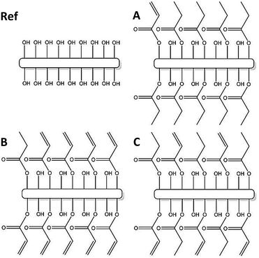
In the present study the use of functionalized porous CNF nanopapers in structural composite electrolytes is explored as the reinforcing phase in a composite with an ionic conductive polymer matrix. Previous work has addressed the difficulties associated with phase migration when two phases of, for instance, different polarities are to be used in a composite.22,31 This also becomes critical if one of the phases changes geometry after manufacturing. In the scope of polymer or gel electrolytes, high ionic conductivity is mostly achieved through swelling of the polymer using a liquid electrolyte. Consequently, it is crucial to have a composite that does not deteriorate during the swelling process. The present study addresses this issue via a post-functionalization of the fibril surfaces to enhance the interfacial strength in the final composite electrolyte. The fibrils are modified through an acid chloride reaction to create acrylate and alkyl groups on the surface. The acrylate can react with a PEG-methacrylate to create covalent bonds between the two, and the alkyl will work as a “dummy”, keeping the number of unmodified OH-groups constant.
2. Experimental
2.1 Materials
All reagents and solvents were used as received with no further purification, except for the lithium salt which was dried under vacuum at 80 °C for two days before entering the glove box.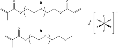 | ||
| Fig. 3 The PEG-methacrylate oligomers: tetraethylene glycol dimethacrylate (a), methoxy polyethylene glycol (350) monomethacrylate (b) and LiPF6 used in the study. | ||
The photoinitiator used was 2,2-dimethoxy-2-phenylaceto-phenone (Irgacure 651) provided by Ciba Specialty Chemicals (Switzerland). For swelling of the composite samples, a 1 M solution of LiPF6 (as mentioned above) in ethyl carbonate (EC) and di-ethyl carbonate (DEC) (1![[thin space (1/6-em)]](https://www.rsc.org/images/entities/char_2009.gif) :
:![[thin space (1/6-em)]](https://www.rsc.org/images/entities/char_2009.gif) 1 by volume) was prepared.
1 by volume) was prepared.
2.2 Techniques & procedures
| Sample name | Acid chloride | ||
|---|---|---|---|
| Acryloyl chloride (I) | Propionyl chloride (II) | Stoichiometry (I![[thin space (1/6-em)]](https://www.rsc.org/images/entities/char_2009.gif) : :![[thin space (1/6-em)]](https://www.rsc.org/images/entities/char_2009.gif) II) II) |
|
| a All sample vials contained 34 μL (0.24 mmol) TEA and a catalytic amount of DMAP. | |||
| Ref1 and 2 | — | — | 0![[thin space (1/6-em)]](https://www.rsc.org/images/entities/char_2009.gif) : :![[thin space (1/6-em)]](https://www.rsc.org/images/entities/char_2009.gif) 0 0 |
| A1, A2 | (0.2 mmol) | (2 mmol) | 1![[thin space (1/6-em)]](https://www.rsc.org/images/entities/char_2009.gif) : :![[thin space (1/6-em)]](https://www.rsc.org/images/entities/char_2009.gif) 9 9 |
| B1, B2 | (2 mmol) | (0.2 mmol) | 9![[thin space (1/6-em)]](https://www.rsc.org/images/entities/char_2009.gif) : :![[thin space (1/6-em)]](https://www.rsc.org/images/entities/char_2009.gif) 1 1 |
| C1, C2 | (1.1 mmol) | (1.1 mmol) | 1![[thin space (1/6-em)]](https://www.rsc.org/images/entities/char_2009.gif) : :![[thin space (1/6-em)]](https://www.rsc.org/images/entities/char_2009.gif) 1 1 |
The modified and unmodified CNF pieces were immersed in a vial containing the monomer mixture, and the vial was connected to a vacuum/argon line. Vacuum was then applied until no bubbles were observed, and the appearance of paper had turned from white to transparent.
At that moment, argon was allowed to enter the vial by increasing the pressure back to normal atmospheric pressure. This cycle was repeated three times to allow complete removal of entrapped air as well as the remaining oxygen. When this was accomplished, the vial containing the monomer mixture as well as the CNF piece was moved inside the glove box. The wet CNF piece was lifted out from the mixture and put between two polyester plastic films (Mylar®). Finally, a microscope lab glass slide was put on top and the sample was irradiated for 10 minutes on one side + 3 minutes on the other under UV irradiation at 15 cm distance from the UV light source, and the resulting, fully cured, still transparent composite electrolyte film was peeled off the Mylar® films. The temperature of the sample did not exceed 42 °C during cure. The light source used for curing was a Blak Ray B-100AP (100 W, 365 nm) Hg UV lamp, which after the aforementioned irradiation time subjects the sample to a total dose of 4.1 J cm−2, as determined using an Uvicure Plus High Energy UV Integrating Radiometer (EIT, USA), measuring UVA at 320–390 nm. After irradiation, the composite electrolyte was swollen in EC![[thin space (1/6-em)]](https://www.rsc.org/images/entities/char_2009.gif) :
:![[thin space (1/6-em)]](https://www.rsc.org/images/entities/char_2009.gif) DEC (1
DEC (1![[thin space (1/6-em)]](https://www.rsc.org/images/entities/char_2009.gif) :
:![[thin space (1/6-em)]](https://www.rsc.org/images/entities/char_2009.gif) 1) for two hours, after which different characterizations were conducted. Additionally, two neat polymer reference samples without any CNF were manufactured. One of them was characterized as such and the other was swollen as described above before characterization.
1) for two hours, after which different characterizations were conducted. Additionally, two neat polymer reference samples without any CNF were manufactured. One of them was characterized as such and the other was swollen as described above before characterization.
![[thin space (1/6-em)]](https://www.rsc.org/images/entities/char_2009.gif) δ) and Tg for the electrolytes presented in Table 2.
δ) and Tg for the electrolytes presented in Table 2.
| Sample name | wt% CNF | E ′25°C [MPa] | E ′100°C [MPa] | σ 25°C [S cm−1] × 10−5 |
|---|---|---|---|---|
| a The density of the CNF nanopaper used in all composites is 618 kg m−3. b The porosity of the CNF nanopaper used in all composites is 58% (eqn (1)). c The neat polymer matrix samples were too brittle to undergo EIS measurements without breaking. | ||||
| CNF nanopaper | 100 | 500 | 435 | n/a |
| Polymer matrix reference (dry) | 0 | 3 | 3 | n/a |
| Polymer matrix reference (swollen) | 0 | 4 | n/a | n/a |
| Ref1 (unmodified) | 47 | 710 | 330 | 1.2 |
| Ref2 (unmodified) | 47 | 690 | 300 | 1.8 |
A1 acrylate![[thin space (1/6-em)]](https://www.rsc.org/images/entities/char_2009.gif) : :![[thin space (1/6-em)]](https://www.rsc.org/images/entities/char_2009.gif) propionate (1 propionate (1![[thin space (1/6-em)]](https://www.rsc.org/images/entities/char_2009.gif) : :![[thin space (1/6-em)]](https://www.rsc.org/images/entities/char_2009.gif) 9) 9) |
36 | 440 | 75 | 7.9 |
A2 acrylate![[thin space (1/6-em)]](https://www.rsc.org/images/entities/char_2009.gif) : :![[thin space (1/6-em)]](https://www.rsc.org/images/entities/char_2009.gif) propionate (1 propionate (1![[thin space (1/6-em)]](https://www.rsc.org/images/entities/char_2009.gif) : :![[thin space (1/6-em)]](https://www.rsc.org/images/entities/char_2009.gif) 9) 9) |
36 | 570 | 100 | 6.6 |
B1 acrylate![[thin space (1/6-em)]](https://www.rsc.org/images/entities/char_2009.gif) : :![[thin space (1/6-em)]](https://www.rsc.org/images/entities/char_2009.gif) propionate (9 propionate (9![[thin space (1/6-em)]](https://www.rsc.org/images/entities/char_2009.gif) : :![[thin space (1/6-em)]](https://www.rsc.org/images/entities/char_2009.gif) 1) 1) |
40 | 470 | n/a | 1.4 |
B2 acrylate![[thin space (1/6-em)]](https://www.rsc.org/images/entities/char_2009.gif) : :![[thin space (1/6-em)]](https://www.rsc.org/images/entities/char_2009.gif) propionate (9 propionate (9![[thin space (1/6-em)]](https://www.rsc.org/images/entities/char_2009.gif) : :![[thin space (1/6-em)]](https://www.rsc.org/images/entities/char_2009.gif) 1) 1) |
40 | n/a | n/a | 1.1 |
C1 acrylate![[thin space (1/6-em)]](https://www.rsc.org/images/entities/char_2009.gif) : :![[thin space (1/6-em)]](https://www.rsc.org/images/entities/char_2009.gif) propionate (1 propionate (1![[thin space (1/6-em)]](https://www.rsc.org/images/entities/char_2009.gif) : :![[thin space (1/6-em)]](https://www.rsc.org/images/entities/char_2009.gif) 1) 1) |
40 | 520 | 160 | 7.0 |
C2 acrylate![[thin space (1/6-em)]](https://www.rsc.org/images/entities/char_2009.gif) : :![[thin space (1/6-em)]](https://www.rsc.org/images/entities/char_2009.gif) propionate (1 propionate (1![[thin space (1/6-em)]](https://www.rsc.org/images/entities/char_2009.gif) : :![[thin space (1/6-em)]](https://www.rsc.org/images/entities/char_2009.gif) 1) 1) |
40 | 350 | 120 | 3.2 |
 | (1) |
3. Results and discussion
The present study includes a series of CNF paper based composite electrolytes with different functionalities on the cellulose fibre surfaces to be used in structural lithium ion battery applications. Neat CNF paper as well as modified were used as reinforcement for the composite electrolytes. The modifications were conducted with different ratios of reactive or inert moieties in order to reveal the influence of both chemical and physical interactions between the reinforcing fibres and the matrix.Data on the sample compositions are found in Table 1. A summary of the obtained data for the electrolyte composites and their precursors is presented in Table 2.
3.1 Modification of CNF nanopapers
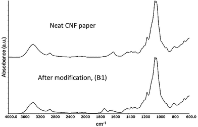
Fig. 6 shows the FT-IR spectra of neat CNF paper and after modification (B1) with the acid chlorides used in this study. It can clearly be seen that after modification, a peak at 1740 cm−1 appears corresponding to the carbonyl group of an ester.35 This suggests a successful modification however, the complex morphology of the fibrillar structure as well as the porous character of the system do not allow for a quantitative determination of the amount of surface modification. It is not possible to quantify, or even detect, the double bonds on the substrate due to the intrinsic low absorptivity of the acrylate double bond (1640 cm−1) and the overlap with the peak emanating from trace amounts of water bound to cellulose.3.2 Composite electrolyte formation
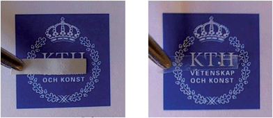
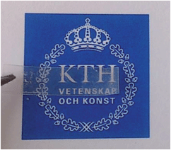
The modified nanopapers were placed in a vial containing the PEG-oligomer solution. The air entrapped in the pores of the nanopaper was removed under vacuum and subsequently replaced by the solution, transforming the nanopaper from white to transparent, Fig. 7.The transparent nature of the impregnated nanopaper indicates a complete removal of entrapped air. It further implies either that the difference in refractive index between the fibres and the matrix is small and/or that the domain sizes in the different phases are smaller than the wavelength of visible light.
3.3 Curing performance
As described in previous studies the UV curing method works well for manufacturing of PEG-methacrylate based composite electrolyte films in the presence of a lithium salt.20,36,37 This approach was found to be versatile for the nanopaper reinforced composite electrolytes investigated in this study. Transparent, flexible, smooth, and easy-to-handle free-standing films were obtained after curing, Fig. 8. The success of the curing reaction was confirmed using FT-IR, monitoring the disappearance of the peak corresponding to the vinyl bond stretch in the methacrylate group of the oligomers (at ∼1640 cm−1 and ∼815 cm−1). The FT-IR spectra, Fig. 8, show the absorption of the uncured oligomer mixture, sample Ref1 after curing, and sample B1 after curing and swelling, verifying full conversion within the detection limit of the FT-IR technique.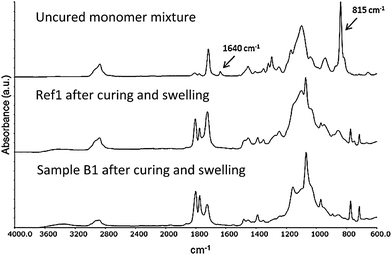 | ||
| Fig. 8 FT-IR spectra of the uncured monomer mixture (top), sample Ref1 (middle) and sample B1 (bottom) after curing and swelling. | ||
3.4 Properties of the composite electrolyte
After curing, smooth, non-sticky, transparent composite electrolytes were obtained (Fig. 9).The readily formed free-standing films were easy to handle, even after post-swelling with a liquid electrolyte, and easily mounted in the characterization instruments used.
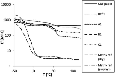
The pure polymer matrix reference exhibits a low Tg around −20 °C with a very low modulus in the rubbery state. The pure CNF paper on the other hand exhibits no detectable phase transition and a relatively high modulus throughout the measurement range. The composite materials all exhibit two phase transitions; one low, corresponding to the pure matrix's Tg and the other transition around 50 °C. This higher transition is proposed to originate from an interphase region in the material i.e. the polymer in close proximity to the fibre surfaces.38 Comparing the unmodified CNF paper with the modified counterpart it is observed that the unmodified exhibits a higher modulus. This can be explained by stronger interactions between the reinforcing fibres when unmodified.
Sample B1, having a large amount of acrylate modification, exhibited a brittle behavior leading to mechanical failure around 60 °C. A plausible explanation is that a combination of high crosslink density at the fibre surfaces and the post-swelling with EC![[thin space (1/6-em)]](https://www.rsc.org/images/entities/char_2009.gif) :
:![[thin space (1/6-em)]](https://www.rsc.org/images/entities/char_2009.gif) DEC induces stresses at the interface with a subsequent loss in ductility.
DEC induces stresses at the interface with a subsequent loss in ductility.
Furthermore, it can be interpreted from these results that in the sample with the lowest amount of acrylates, relatively poor mechanical performance is obtained compared to the sample with an equal amount of acrylate and propionate groups.
All together the results imply that if the interfacial bonds are too few, the polymer is more mobile and undergoes its glass transition with no restraints from the CNF. When the bonds are too many, the composite becomes brittle. With an equimolar modification (samples C1 and C2) the modified composite exhibits an excellent modulus (>100 MPa), even above 100 °C, in its swollen state.
![[thin space (1/6-em)]](https://www.rsc.org/images/entities/char_2009.gif) :
:![[thin space (1/6-em)]](https://www.rsc.org/images/entities/char_2009.gif) 9 composition (acryloyl chloride
9 composition (acryloyl chloride![[thin space (1/6-em)]](https://www.rsc.org/images/entities/char_2009.gif) :
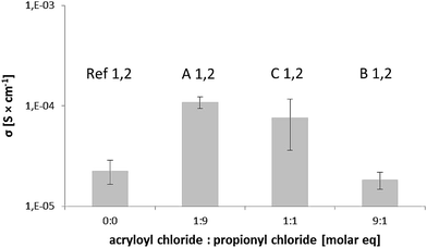
:![[thin space (1/6-em)]](https://www.rsc.org/images/entities/char_2009.gif) propionyl chloride) have a value of almost a decade higher than the reference samples.
propionyl chloride) have a value of almost a decade higher than the reference samples.
The samples based on unmodified CNF (Ref1 and 2) measure lower due to the fact that the polymer has left the composite during the swelling process and ionic pathways are obstructed. When considering the samples with a larger amount of acrylate groups, their ionic transporting ability is reduced. This is most likely due to the limited segmental mobility of the PEG segments as a consequence of the covalent bonds between the phases. Furthermore, samples Ref1 and 2 show a more moderate ionic conductivity as well indicating a strong fibre/matrix interaction in the solid state.
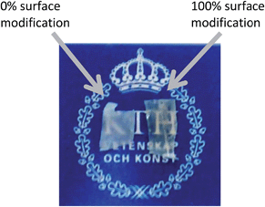 | ||
| Fig. 12 The composite electrolyte with unmodified CNF nanopaper (left) and modified CNF nanopaper (right) after swelling in EtOH for 48 hours. | ||
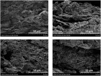
This can be interpreted so that a larger amount of polymer is removed from the unmodified CNF paper than from the modified counterpart. This is a strong indication that the polymer is covalently attached to the CNF in the latter case. These results furthermore indicate the importance of a strong interface in the composite material when the material is subjected to swelling stresses.
The possibility of the polymer electrolyte to diffuse out of the system will be important for the long term performance of the composite electrolyte in a battery application. Not only will the load bearing ability be affected but also the electrochemical behavior will deteriorate with increased porosity. Changes in geometry have also imposed in a battery during charging/uncharging cycles why a strong interface is needed. This study suggests that a strong interface can be obtained when the ion conducting matrix is covalently anchored.
4. Conclusions
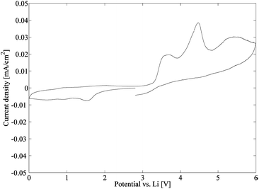
In this study, a series of 4 composite electrolytes has been successfully manufactured. The composite electrolytes are constituted of a soft, ion conducting polymer matrix having a stiff CNF nanopaper as reinforcement. The reference samples contain unmodified CNFs, while the other samples in the series are surface modified by a straightforward reaction to create covalent bonds between the CNF and the polymer matrix to different extents. After swelling the composite electrolytes with liquid electrolytes, the sample with the lowest amount of acrylate modification is the best ionic conductor. However, when both the mechanical properties and ion conducting performance are considered, the samples modified by an equimolar solution of propionyl chloride and acryloyl chloride perform best, having an elastic modulus >100 MPa above 100 °C and an ion conductivity of around 5 × 10⁻⁵ S cm−1 at 25 °C. In conclusion, these promising results by far meet the criteria set up by Snyder et al. for structural batteries (E′> 150 MPa, σ > 1 × 10⁻⁵ S cm−1),14 and further studies regarding these composites are currently undertaken. Finally, the resulting currents from the cyclic voltammetry measurements illustrate a relatively stable electrochemical behaviour of the composite electrolyte.Acknowledgements
The Swedish Energy Agency is greatly acknowledged for financial support, grant #37712-1 “Structural composite batteries for energy efficient vehicles”. The monomers used were supplied by Sartomer Company which is thankfully acknowledged. Linn Carlsson and Nicholas Cervin are acknowledged for providing CNFs and Christian Porsch for valuable discussions and input on this article.Notes and references
- E. D. Wetzel, Reducing weight: Multifunctional composites integrates power, communications, and structure, AMPTIAC Q., 2004, 8(4), 91–95 CAS.
- J. M. Tarascon and M. Armand, Issues and challenges facing rechargeable lithium batteries, Nature, 2001, 414(6861), 359–367 CrossRef CAS PubMed.
- R. Spotnitz and J. Franklin, Abuse behavior of high-power, lithium-ion cells, J. Power Sources, 2003, 113(1), 81–100 CrossRef CAS.
- B. Yebka, J. A. Holung and T.-L. Wong, Battery safety features, Lenovo (Singapore) Pte. Ltd., Singapore, 2010, U.S. Pat. Appl. Publ. US., p. 11 Search PubMed.
- P. Liu, E. Sherman and A. Jacobsen, Design and fabrication of multifunctional structural batteries, J. Power Sources, 2009, 189(1), 646–650 CrossRef CAS.
- M. B. Armand, M. J. Duclot and P. Rigaud, Polymer solid electrolytes: stability domain, Solid State Ionics, 1981, 3–4, 429–430 CrossRef CAS.
- M. Armand, Polymer solid electrolytes - an overview, Solid State Ionics, 1983, 9–10(pt 2), 745–754 CrossRef CAS.
- C. Berthier, et al., Microscopic investigation of ionic conductivity in alkali metal salt-poly(ethylene oxide) adducts, Solid State Ionics, 1983, 11(1), 91–95 CrossRef CAS.
- D. F. Shriver, et al., Structure and ion transport in polymer-salt complexes, Solid State Ionics, 1981, 5, 83–88 CrossRef CAS.
- G. Bao, et al., Ionic conductivity of polyelectrolyte derivatives of poly(vinyl alcohol) - lithium ion complex films, Polym. Bull., 1987, 18(2), 143–148 CrossRef CAS.
- Y. Choi, et al., Ultraviolet radiation curing of acrylates for lithium polymer electrolytes, J. Appl. Electrochem., 1997, 27(9), 1118–1121 CrossRef CAS.
- D. E. Fenton, J. M. Parker and P. V. Wright, Complexes of alkali metal ions with poly(ethylene oxide), Polymer, 1973, 14(11), 589 CrossRef CAS.
- P. V. Wright, Electrical conductivity in ionic complexes of poly(ethylene oxide), Br. Polym. J., 1975, 7(5), 319–327 CrossRef CAS.
- J. F. Snyder, R. H. Carter and E. D. Wetzel, Electrochemical and Mechanical Behavior in Mechanically Robust Solid Polymer Electrolytes for Use in Multifunctional Structural Batteries, Chem. Mater., 2007, 19(15), 3793–3801 CrossRef CAS.
- J. F. Snyder, E. D. Wetzel and C. M. Watson, Improving multifunctional behavior in structural electrolytes through copolymerization of structure- and conductivity-promoting monomers, Polymer, 2009, 50(20), 4906–4916 CrossRef CAS.
- J. P. Thomas and M. A. Qidwai, The design and application of multifunctional structure-battery materials systems, J. Occup. Med., 2005, 57(3), 18–24 CAS.
- X. Hou and K. S. Siow, Ionic conductivity and electrochemical characterization of novel interpenetrating polymer network electrolytes, Solid State Ionics, 2002, 147(3–4), 391–395 CrossRef CAS.
- D. He, et al., Enhanced Ionic Conductivity of Semi-IPN Solid Polymer Electrolytes Based on Star-Shaped Oligo(ethyleneoxy)cyclotriphosphazenes, Macromolecules, 2012, 45(19), 7931–7938 CrossRef CAS.
- P. Meneghetti, S. Qutubuddin and A. Webber, Synthesis of polymer gel electrolyte with high molecular weight polymethyl methacrylate-clay nanocomposite, Electrochim. Acta, 2004, 49(27), 4923–4931 CrossRef CAS.
- J. R. Nair, et al., UV-cured polymer electrolyte membranes for Li-cells: Improved mechanical properties by a novel cellulose reinforcement, Electrochem. Commun., 2009, 11(9), 1796–1798 CrossRef CAS.
- A. Chiappone, et al., Microfibrillated cellulose as reinforcement for Li-ion battery polymer electrolytes with excellent mechanical stability, J. Power Sources, 2011, 196(23), 10280–10288 CrossRef CAS.
- J. R. Nair, et al., Novel cellulose reinforcement for polymer electrolyte membranes with outstanding mechanical properties, Electrochim. Acta, 2011, 57, 104–111 CrossRef CAS.
- S.-J. Chun, et al., Eco-friendly cellulose nanofiber paper-derived separator membranes featuring tunable nanoporous network channels for lithium-ion batteries, J. Mater. Chem., 2012, 22(32), 16618–16626 RSC.
- S. Leijonmarck, et al., Single-paper flexible Li-ion battery cells through a paper-making process based on nano-fibrillated cellulose, J. Mater. Chem. A, 2013, 1(15), 4671–4677 CAS.
- S. J. Eichhorn, et al., Review: current international research into cellulose nanofibres and nanocomposites, J. Mater. Sci., 2010, 45(1), 1–33 CrossRef CAS.
- T. Saito, et al., Homogeneous Suspensions of Individualized Microfibrils from TEMPO-Catalyzed Oxidation of Native Cellulose, Biomacromolecules, 2006, 7(6), 1687–1691 CrossRef CAS PubMed.
- T. Saito, et al., Individualization of Nano-Sized Plant Cellulose Fibrils by Direct Surface Carboxylation Using TEMPO Catalyst under Neutral Conditions, Biomacromolecules, 2009, 10(7), 1992–1996 CrossRef CAS PubMed.
- A. E. Horvath and T. Lindström, The influence of colloidal interactions on fiber network strength, J. Colloid Interface Sci., 2007, 309(2), 511–517 CrossRef CAS PubMed.
- A. Sturcova, G. R. Davies and S. J. Eichhorn, Elastic Modulus and Stress-Transfer Properties of Tunicate Cellulose Whiskers, Biomacromolecules, 2005, 6(2), 1055–1061 CrossRef CAS PubMed.
- S. Iwamoto, et al., Elastic Modulus of Single Cellulose Microfibrils from Tunicate Measured by Atomic Force Microscopy, Biomacromolecules, 2009, 10(9), 2571–2576 CrossRef CAS PubMed.
- J. J. Peterson, et al., Surface-Grafted conjugated polymers for hybrid cellulose materials, J. Polym. Sci., Part A: Polym. Chem., 2011, 49(14), 3004–3013 CrossRef CAS.
- S. Katz, R. P. Beatson and A. M. Scallan, The determination of strong and weak acidic groups in sulfite pulps, Sven. Papperstidn., 1984, 87(6), R48–R53 CAS.
- L. Wågberg and R. Hägglund, Kinetics of polyelectrolyte adsorption on cellulosic fibers, Langmuir, 2001, 17(4), 1096–1103 CrossRef.
- C. C. Sun, Mechanism of moisture induced variations in true density and compaction properties of microcrystalline cellulose, Int. J. Pharm., 2008, 346(1–2), 93–101 CrossRef CAS PubMed.
- A. Carlmark and E. Malmström, Atom Transfer Radical Polymerization from Cellulose Fibers at Ambient Temperature, J. Am. Chem. Soc., 2002, 124(6), 900–901 CrossRef CAS PubMed.
- M. Willgert, et al., Photoinduced free radical polymerization of thermoset lithium battery electrolytes, Eur. Polym. J., 2011, 47(12), 2372–2378 CrossRef CAS.
- M. Willgert, et al., New structural lithium battery electrolytes using thiol-ene chemistry, Solid State Ionics, 2013, 236, 22–29 CrossRef CAS.
- D. Ståhlberg, et al., Relaxation properties of particle filled coatings: Experimental study and modelling of a screw joint, Prog. Org. Coat., 2006, 55(2), 112–118 CrossRef.
| This journal is © The Royal Society of Chemistry 2014 |


