Chemical transformations of nanomaterials for energy applications
M.
Fayette
and
R. D.
Robinson
*
Department of Materials Science & Engineering, Cornell University, Ithaca, NY 14853, USA. E-mail: rdr82@cornell.edu
First published on 15th November 2013
Abstract
Chemical Transformations of Nanomaterials (CTNMs) is a powerful method to modify as-synthesized nanomaterials into forms with novel composition and structure. CTNMs allows access to nano-based materials that are difficult to synthesize by conventional means, including metastable materials through partial transformations. These new nanomaterial forms can have property and stability advantages when used for energy applications. This short review highlights recent research progress in chemical transformations of non-metallic nanomaterials as a means to create useful energy materials, such as metastable structures, with a focus on fuel cell catalysts and battery technologies. In addition to discussing progress with chemically transformed materials, this review briefly highlights several metastable materials that have been used for energy applications but were synthesized through conventional means. Synthetic protocols of CTNMs could be used to produce these metastable energy materials, which may result in novel properties. Finally, the review concludes with a forward looking perspective of metastable materials that have yet to be synthesized, but are good candidates for catalysis/batteries as metastable materials. These proposed systems could yield next generation catalysts/battery materials.
1. Introduction
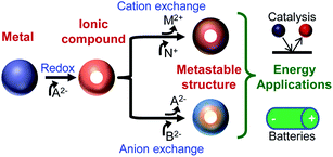
In the past decade, chemical transformations of nanomaterials (NMs) has emerged as a powerful new means for nanosynthetic chemistry.1–27 Chemical transformations of nanomaterials (CTNMs) are reactions that are performed on first-generation (as-synthesized) nanomaterials to modify their chemical composition, atomic structure, morphology, and/or size. CTNMs include redox reactions (either addition or exchange) and ionic exchange (cation and anion exchange) (Fig. 1). The popularity of CTNMs has been driven by their ability to create new NM forms14,18,28 that are difficult or inaccessible from conventional syntheses (e.g., the “hot-injection” method) such as, Cu2S nanorods12 and unique core–shell/shell combinations like PbSe–CdSe/ZnS.7 But perhaps the most exciting and untapped feature of CTNMs is its capacity to form metastable phases, such as striped heterostructured nanorods,3,6 crystalline–amorphous core–shell and interdiffused NMs,29,30 and doped NMs21,23,31 (Fig. 2). Thus CTNMs is emerging as a powerful tool to tailor the composition and phase of nanomaterials, as well as produce a series of compositionally interesting metastable structures.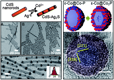 | ||
| Fig. 2 Metastable Intermediate states during chemical transformation of nanomaterials. (left) TEM images of spontaneous nanorod superlattice formation formed through partial cation exchange. (A) Original 4.8 × 64 nm CdS nanorods. (B and C) Transformed CdS–Ag2S superlattices. Inset to (C) is a histogram of Ag2S segment spacing (center-to-center, nm). (right) An amorphous Co–P phase precedes the nanoscale Kirkendall effect. (top right) Schematic of Co nanoparticles with amorphous Co–P shell converting into Co2P shell and subsequent initiation of Kirkendall hollowing. (bottom right) False color image of high-resolution TEM showing amorphous Co–P shell (red) on crystalline Co core (blue). Adapted with permission from ref. 3, Copyright 2007 AAAS, and ref. 29, Copyright 2011 Royal Society of Chemistry. | ||
A number of previous CTNMs studies have focused on changes to the electronic and/or optical properties.7,13,21,31 Less work has been done specifically utilizing CTNMs to manipulate composition to produce useful energy materials. Of interest is the use of chemical transformations to access metastable materials, which for the balance of this article refers to heterostructures (graded composition or sharp interfaces, e.g., striped CdS–Ag2S nanorods3,6), doped phases (e.g., Co-rich Co2P (supra-stoichometric)29), interdiffused phases (e.g., ε-Co with CoO30), and/or amorphous structures (e.g., ε-Co crystalline core with a Co–P amorphous shell29). Also included in the metastable class of materials is the formation of crystalline structures of materials that are normally unstable when synthesized via conventional means (e.g., hexagonal Cu2Se).20 All of these types of metastable structures can be considered as a new class of unique materials that could potentially lead to the next generation of nano-energy materials32,33 (e.g., for fuel cells and/or Li-ion batteries). CTNMs can be a powerful means to convert NMs into useful new metastable structures for energy applications (Fig. 1).
Metastable and mixed phase metals have notably already proven their worth in the area of catalysis, where certain alloys have been extensively studied in order to alter the electronic structure of the parent material to achieve higher activity and/or stability than their pure phase/composition analogues. This was famously demonstrated with thin films of Pt3Ni(111) that were shown to have 10× the oxygen reduction reaction (ORR) catalytic activity of pure Pt(111) surfaces and to be over 90 times more efficient at ORR than Pt nanoparticles, most likely due to a d-band shift of the Pt lattice due to alloying with Ni.34 Bimetallic core–shell metal nanoparticles have demonstrated similar exceptional catalytic properties due to synergetic effects (e.g., Au–Pd).35 Pt–Pt3Co36 catalysts have been reported to have the highest mass activity of all Pt–Co catalysts for ORR, showing the applicability of bimetallic core–shell nanomaterials. Metastable ionic/covalent nanomaterials, however, are less rigorously studied in relation to energy applications; clearly there is much room for new discoveries in this area.
Herein, we present a forward-looking review article that discusses the use of chemical transformations of nanomaterials to produce useful products for energy applications, specifically, the hydrogen evolution reaction (HER), the oxygen reduction reaction (ORR), and Li-ion battery materials. This article will focus on non-metallic NMs. In Section 2 we present an overview of the concepts of CTNMs. Section 3 gives several examples of nanomaterials for energy applications that were synthesized via chemical transformation protocols. This section is designed to illustrate the utility of these materials for catalysis and electrochemical energy storage. Section 4 highlights metastable materials used in energy applications that have not been formed through CTNMs but should be accessible by CTNMs. In the final section (Section 5) we propose new metastable material systems for energy applications that can be synthesized through chemical transformations of nanomaterials, and should have certain advantages over their pure phase analogues.
2. Overview of Chemical Transformations of Nanomaterials (CTNMs)
From a review of recent literature it is clear that the new focus of nanoparticle synthesis and characterization has migrated from first-generation (as-synthesized) to nanomaterials that are derived from the first-generation nanomaterials.37 The large surface to volume ratio of nanomaterials, and finite number of constituent atoms, allows chemical transformations to behave differently at the nanoscale than in bulk. For instance, in nanomaterials the high activation barriers for diffusion may be reduced, permitting rapid diffusion of atoms in a solid,1 which can then enable the formation of new metastable structures.3 CTNMs is defined as reactions performed on as-synthesized nanomaterials to chemically adjust their composition, structure, and/or morphology. The chemical transformation may be an addition or an exchange reaction. The driving forces for these reactions are either a redox couple or the thermodynamics of the solvation of the ions in solution versus in a solid. In the simplest case of a redox exchange reaction, metal (M) particles in the presence of excess cations/species (N+z) results in the oxidation of M along with the reduction of the cationic species, leading to N0 particles provided that N+z/N has higher reduction potential than M. An example of a redox exchange chemical transformation as recently shown with Mn3O4 in the presence of Fe(ClO4)3, that transformed into hollow Mn3O4–Fe2O3 nanoboxes with the final product being hollow Fe2O3 nanocrystals.38 This was explained through the reduction potential of the Fe+3/Fe+2 (E = 0.77 V SHE) driving the reduction of Mn3O4/Mn+2 (E = 1.82 V SHE).In a redox addition reaction when the initial NM atoms become oxidized and the foreign atoms are reduced there is the possibility for a nanoscale Kirkendall effect, but if the initial atoms are reduced then the Kirkendall effect is not usually observed.39 An example of a redox addition reaction with the nanoscale Kirkendall effect, metal M particles annealed in the presence of O2 (a covalent system) result in an oxidation of the metal and a reduction of the oxygen, based upon their relative reduction potentials, producing MxOy. The asymmetric diffusion rates between the two atomic components in the diffusion couple can result in a hollow nanomaterial, called the nanoscale Kirkendall effect. This was originally demonstrated in the cobalt metal system, transforming the Co NMs into hollow cobalt chalcogenides2,40 (Fig. 3). Researchers had originally believed that the Kirkendall hollowing was a straightforward mechanism in nanomaterials, directly related to the bulk Kirkendall effect. However, recent work using X-ray absorption spectroscopy and density functional theory on the cobalt oxide and cobalt phosphide systems has found that the mechanism of the nanoscale Kirkendall effect more complex than previously believed: the nanoscale Kirkendall effect is not a one-step process where hollowing simply occurs due to asymmetric diffusion rates between the anion and cation, but involves several distinct steps resulting from phase-related diffusion constants and processes.29,30 For instance, for nanoparticles of cobalt converting into cobalt oxide, oxygen diffuses inward into the ε-Co in the beginning of the transformation, forming an amorphous Co–O layer. When the major phase of this layer becomes crystalline CoO outward diffusion of Co becomes more favorable.30 The oxygen diffuses inward through an interesting indirect two-step mechanism, with the O hopping between interstitial sites and type I Co vacancies.30 The cobalt phosphide system was shown to follow a similar process, with phosphorous in-diffusion initially faster than cobalt out-diffusion, but once the Co–P amorphous shell crystallizes to Co2P then the diffusion rates invert and the characteristic Kirkendall hollowing is seen.29 Characterization of this process identified a new metastable amorphous state that precedes the Kirkendall hollowing (Fig. 2, right).29
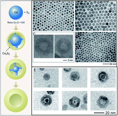 | ||
| Fig. 3 Redox addition reaction and accompanying nanoscale Kirkendall effect. (left) Schematic showing Co nanoparticles in presence of sulfur transforming into Co9S8via redox addition, and resulting in hollow Co9S8 due to the nanoscale Kirkendall effect. (A) TEM images of initial Co nanoparticles. (B) Co3S4 hollow nanoparticles after injection of sulfur into Co nanoparticle solution. (C) HRTEM images of Co3S4 (left) and Co9S8 (right). (D) TEM image of hollow Co9S8. (E) Formation of hollow CoSe. Adapted with permission from ref. 2 and 40, Copyright 2004 AAAS. | ||
Ionic exchange is another method to chemically transform nanomaterials. The most prevalent of these is the cation exchange in which a compound such as CdSe in the presence of Ag+ ions transforms into Ag2Se + Cd+2 (Fig. 4). The driving force behind these exchanges is solvation, meaning that the parent cation is more soluble in solution than in the solid, resulting in a net dissolution of the parent cation in the presence of excess daughter cations.41 The process is also aided by the high surface area/volume of the nanomaterials, which lowers the activation energy for the diffusion of the cations.41
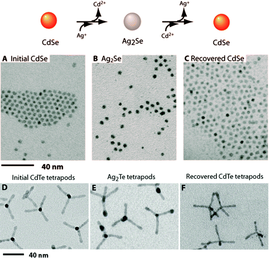 | ||
| Fig. 4 Reversible cation exchange in nanocrystals. (top) Schematic showing cation exchange between CdSe and Ag2Se nanocrystals. (below) TEM images of: (A) initial CdSe nanoparticles, (B) cation exchanged Ag2Se particles, and (C) recovered CdSe from second cation exchange. (D–F) Cation exchanged CdTe and Ag2Te tetrapods. Adapted with permission from ref. 1, Copyright 2004 AAAS. | ||
The reaction time for ion exchange can be much faster in nanoparticles than would be expected by scaling a bulk characteristic time to a nano-scale material. Considering diffusion, using the values reported for large Cd particles,8 the diffusivity of Cd in CdS extrapolated to room temperature is ∼10−21 cm2 s−1.42 For a nanomaterial with a characteristic dimension of 10 nm the diffusion time is then ∼108 s.43 However, cationic diffusion-based exchanges occur on the order of milliseconds at room temperature in nanoparticles,1,44 indicating that other effects may be at play.
Cation exchange reactions have been used to convert CdS to Cu2S, forming interfaces as the Cu2S forms at the ends of the precursor nanorods and then grows inwards, which was attributed to high stability of the CdS–Cu2S interfaces.10 Cation exchange has been used to dope particles31 and to create highly luminescent particles.45
The other form of ionic exchange is the anion exchange. Anionic exchange is not as common as cationic exchange, but there are several reports11,46–49 in the literature, such as the conversion of Al2O3 to AlN.50 Anionic exchanges occur when a compound such as MX is in solution (or in contact with) anion Y−2, which replaces the precursor anion to form M2Y + X−. It has been shown for the conversion of ZnS to ZnO as the exchange between S−2 and O−2 occurs, the Zn+2 ions start diffusing outwards. As the Zn+2 diffuses outwards, O diffuses faster than S, leading to the formation of hollow ZnO that has the same crystalline structure as the original ZnS.11 An interesting anion exchange was reported to create heterostructured rods, in which Ag8W4O16 nanorods were transformed into Ag8W4O16–AgCl by reacting NaCl with the precursor nanorods.51 Recently, our group has shown that (NH4)2S can be used as a low temperature anion exchange reagent in solution by transforming CoO nanoparticles to Co3S4.24
As described above, the use of chemical transformations has yielded exciting new nanomaterials with interesting structures and compositions. These new material forms give rise to an expanded set of properties that can have useful applications. Of the novel properties that result for CTNMs, doping of nanomaterials through partial cation exchange has gained attention for controlling optical properties,52 making them useful for photovoltaics53 as well as plasmonics.54,55 For example, it has been shown that Ag+ doping of CdSe shows enhanced fluorescence combined with transition from n-type to p-type depending on doping level.23 However, other applications of CTNMs have received less attention. With such composition and structure control, CTNMs should be useful for tailoring metastable materials for alternative energy sources, particularly fuel cell catalysis as well as Li-ion battery materials.
The field of fuel cell catalysis has attracted interest due to the propensity of clean renewable energy. Generally, the hydrogen fuel cell is regarded as the most promising configuration because of the high potential differences between the anodic reaction (H2 oxidation) and the cathodic reaction (ORR). Since a fuel cell is in essence a galvanic cell with replaceable cathodic and anodic reactants, a large potential difference between the two compartments is ideal. With a larger potential gap, the reaction becomes more energetically and thermodynamically favorable, thus more power will be produced. In the hydrogen fuel cell, the potential difference is approximately 0.7–0.9 V, depending upon the catalyst used. However, a critical component is the high cost of the precious metals used as catalysts along several stages in the cycle of fuel cells, from generating the H2 fuel to reducing the O2 during operation. The development of a catalyst to generate the hydrogen fuel through the hydrogen evolution reaction (HER) is a key focus of research within the past decade. The most common catalysts for this reaction are the Pt-group metals, specifically Pt56−59 and Pd.57,60 As a result of their high cost and rarity in nature, much work has been done to limit the amount of these materials or to find promising alternatives such as MoS2.61–63
Within the operation of the fuel cell the majority of catalysis research is focused on the cathodic reaction, ORR. As with HER, it is widely accepted that the best metal catalyst for ORR is Pt.58,64 To reduce the amount of Pt needed researchers are investigating the use of Pt alloys such as Pt3Ni,34,65,66 as well as the use of thin films67–73 and nanomaterials.74,75 In addition, work has been aimed at finding alternatives to Pt, mainly the use of metal chalcogenides such as Co3O4.76–78 It is worth noting that metastable materials have not been extensively tested for HER/ORR, which, considering the unique electronic effects that are possible in metastable compositions, warrants further investigation. Additionally, chemical transformations could impart advantages such as manipulating composition of the NM to be a controlled amalgam of two well-known catalysts to take advantage of each of their strengths, or formation of graded core–shell structures that could impart a soft-confinement potential.79
For electrochemical energy storage, Li-ion batteries have already been commercialized on a large scale with the main cathodic material being LiCoO2. LiCoO2 is well known to degrade under high applied voltages but improvements continue to be made.80,81 New cathodic materials with low cost and low charging times are being investigated, such as LiFePO4.82–87 It should be noted that the low charging time of LiFePO4 is due to low electronic conductivity86,87 in the plateau region. However, work in this area continues as battery materials with higher capacitance coupled with longer cycling ability are needed. In particular, the use of cobalt oxides has been well studied with Co3O488–91 being among the most examined anodic materials. Most of the battery nanomaterials are synthesized directly into their stable form. To the best of our knowledge, little work has been done on the use of CTNMs in order to engineer advanced materials. The ability to access new cathodic/anodic phases could lead to materials with high stability/performance.
The next section briefly summarizes materials synthesized via chemical transformation protocols for fuel cell catalysis as well as Li-ion battery technology. Specifically, the materials presented highlight the different methodologies of CTNM discussed in the previous section as shown in Fig. 1.
3. Chemical transformations of nanomaterials used in energy applications
In this section we discuss direct examples of CTNMs for energy applications. We focus on several examples from literature where the as-synthesized nanomaterial was chemically transformed to produce a more useful material for the specific application. The reactions chosen highlight energy applications that are among the most heavily investigated: HER, ORR and Li-ion battery anode materials.3.1. Hydrogen Evolution Reaction (HER)
The use of noble metals for catalysis has been studied in part because of their high stability. Nanomaterial catalysts replaced bulk catalysts due to the scarcity of noble metals, coupled with the high surface area/volume ratio afforded by nanomaterial-based catalysts. The scarcity of Pt-group metals has necessitated an in-depth analysis of non-Pt based catalysts for HER. Interest has also been drawn away from electrochemical catalysis and more toward renewable methods, such as photocatalysis.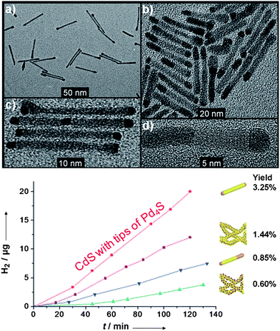 | ||
Fig. 5 CdS–PdX hybrid structures for HER. (a–d) CdS nanorods with tip growth of Pd4S formed through a modified cation exchange reaction. (bottom) Photocatalytic H2 production by  CdS with tips of Pd4S, compared against heterostructures of CdS with tips of Pd4S, compared against heterostructures of  CdS rods with small PdO dots, CdS rods with small PdO dots,  CdS with body exchanged Pd4S, and CdS with body exchanged Pd4S, and  CdS rods with large PdO dots. Adapted with permission from ref. 92, Copyright 2011 Wiley. CdS rods with large PdO dots. Adapted with permission from ref. 92, Copyright 2011 Wiley. | ||
The photocatalytic properties were tested in sulfide/sulfite solution (Fig. 5). The nanorods with a small amount of Pd4S are 2 times (∼9.5 μg h−1) more efficient at H2 evolution than the small particle PdO based CdS hybrids that were also synthesized. A major consideration in this reaction is the ability to produce hydrogen consistently over time. Even though the yield of the CdS–Pd4S nanorods was low based upon the amount of photons adsorbed/mass H2 generated, the catalytic response was essentially a linear function. It is interesting to note that the amount of Pd4S dictates the activity (more Pd4S leads to a worse performance). The proposed mechanistic rationale was through a raised Fermi level in the Pd4S catalyst, in which the high Fermi level permits better electron transfer to nearby water molecules. Another possibility is that larger Pd4S sites near the CdS–Pd4S interface favor electron–hole recombination versus electron transfer to water.
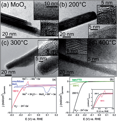 | ||
| Fig. 6 MoO3–MoS2 core–shell nanowires obtained through anion exchange for HER. (a) Original MoO3 nanowires. (b–d) Anion exchanged nanowires at reaction temperatures 200, 300, and 400 °C. (bottom left) Electrochemical activity of initial MoO3 wires (blue) and MoO3–MoS2 core–shell nanowires anion exchanged at 150 °C (red). (bottom right) Electrochemical activity of MoO3–MoS2 core–shell nanowires anion exchanged at 200 and 300 °C, and FTO support substrate. Adapted with permission from ref. 61, Copyright 2011 American Chemical Society. | ||
The Mo-based nanowires were then tested for their electrochemical performance for the HER (Fig. 6) in 0.5 M H2SO4. Compared to MoO3, MoS2 has high stability in acidic solution, while MoO3 is unstable and readily decomposes. The MoS2 begins to evolve H2 at ∼−0.15–0.2 V negative of the H2 equilibrium potential, which is approximately 50 mV more negative than on Pt(111) and Pt(100) catalysts,56 meaning, the amount of energy to initiate HER on Pt56,57 is less than the Mo-based catalyst. The Mo-based catalyst has an extremely high current density of 10 mA cm−2 that is higher than Pt single crystals56,57 (MoO3–MoS2 has a more negative onset potential than Pt as HER electrochemical activity is potential-based), indicating good activity for the reaction. The catalyst was exceptionally durable: the material is stable for over 10![[thin space (1/6-em)]](https://www.rsc.org/images/entities/char_2009.gif) 000 cycles with no loss of activity as the stability is attributed to the metal sulfide shell protecting the metal oxide core from dissolution. It is important to note that the top performing MoO3–MoS2 core–shell nanowires were obtained through a partial anion exchange, with the wires retaining crystal character from both MoS2 and MoO3. This reinforces the benefits of metastable materials produced through CTNMs for their system.
000 cycles with no loss of activity as the stability is attributed to the metal sulfide shell protecting the metal oxide core from dissolution. It is important to note that the top performing MoO3–MoS2 core–shell nanowires were obtained through a partial anion exchange, with the wires retaining crystal character from both MoS2 and MoO3. This reinforces the benefits of metastable materials produced through CTNMs for their system.
3.2. Oxygen Reduction Reaction (ORR)
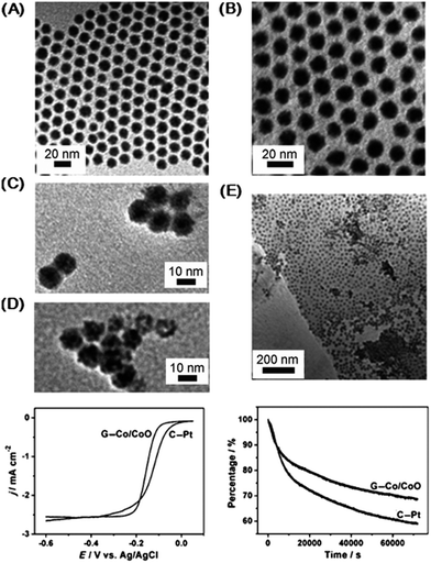 | ||
| Fig. 7 Co–CoO core–shell nanoparticles formed through redox addition reaction for ORR. (A) TEM images of initial Co nanoparticles. (B) Final Co–CoO. (C and D) Co–CoO nanoparticles after different air exposure times (17 h, 96 h). (E) Co–CoO nanoparticles deposited on graphene (G–Co–CoO). (bottom left) ORR polarization curves of the G–Co–CoO and Pt nanoparticles on glassy carbon (C–Pt). Solution: O2 saturated 0.1 M KOH. Scan rate: 10 mV s−1. Rotation rate: 400 rpm. (bottom right) Chronoamperometry at −0.3 V for the ORR on the G–Co–CoO nanoparticles and commercial C–Pt catalysts. Solution: O2 saturated 0.1 M KOH. Rotation rate: 200 rpm. Adapted with permission from ref. 93, Copyright 2012 Wiley. | ||
The Co–CoO catalyst was tested for ORR and showed favorable results when dispersed on graphene (Fig. 7). Compared to Pt nanoparticles, the Co–CoO catalyst has comparable activity: the E1/2 potential difference between the Pt and Co–CoO is 0.025 V, but the Co–CoO has a higher current density and steeper polarization curve. (The E1/2, which is the half width potential in the polarization curve, is a catalyst comparison characterization tool that can be used as an alternative to comparing the onset potential for ORR). Longer nanoparticle annealing times shift the ORR kinetics to more negative potentials, due to the structural changes in the nanoparticles (NPs) as the oxide shell thickens. Under chronoamperometric conditions, the Co–CoO catalyst has higher stability than pure Pt for 60![[thin space (1/6-em)]](https://www.rsc.org/images/entities/char_2009.gif) 000 s (Fig. 7). Rotating Disk Electrode (RDE) results show that the Co–CoO catalyst reduces oxygen via a 4e-pathway based upon information resolved from the Levich plot. (RDE rotates the working electrode whereby laminar flow of solution towards and across the electrode results in current signal if redox species is present). The Co–CoO catalyst has higher activity and durability for ORR than Pt even though the E1/2 is less than Pt. Overall, these results indicate that this material would be an encouraging replacement for Pt in alkaline fuel cells. It is noteworthy that peak performance was achieved through a partial chemical transformation, resulting in a 1 nm CoO shell. Previous work on this system by our group using X-ray absorption spectroscopy points to an amorphous CoO and potentially interdiffused interface between structures of CoO and Co.30
000 s (Fig. 7). Rotating Disk Electrode (RDE) results show that the Co–CoO catalyst reduces oxygen via a 4e-pathway based upon information resolved from the Levich plot. (RDE rotates the working electrode whereby laminar flow of solution towards and across the electrode results in current signal if redox species is present). The Co–CoO catalyst has higher activity and durability for ORR than Pt even though the E1/2 is less than Pt. Overall, these results indicate that this material would be an encouraging replacement for Pt in alkaline fuel cells. It is noteworthy that peak performance was achieved through a partial chemical transformation, resulting in a 1 nm CoO shell. Previous work on this system by our group using X-ray absorption spectroscopy points to an amorphous CoO and potentially interdiffused interface between structures of CoO and Co.30
3.3 Li-ion batteries
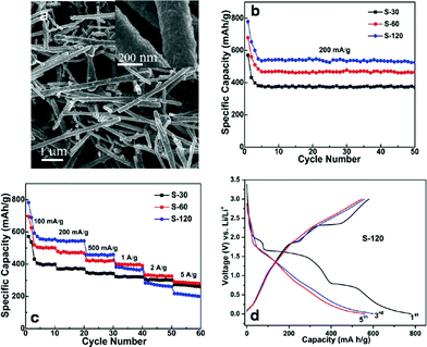 | ||
| Fig. 8 Cu–CuxS core–shell nanotubes obtained through addition reaction for Li-ion battery electrodes. (a) Low-magnification and (inset) high-magnification FESEM image of Cu–CuxS core–shell nanotubes. (b) Cycling performance of the Cu–CuxS nanotube samples with different synthesis reaction times (30, 60, and 120 min). Current density: 200 mA g−1. Potential Range: 0.001–3.0 V. (c) Cycling performance (varying current densities) of the Cu–CuxS nanotubes with different synthesis times (30, 60, and 120 min). (d) Charge–discharge curves (1,3, and 5 cycles) for Cu–CuxS. Current density: 200 mA g−1. Adapted with permission from ref. 95, Copyright 2012 American Chemical Society. | ||
The Cu–CuxS nanotubes were tested as both a cathode and anode for a Li-ion battery (Fig. 8). Although there is not an extensive plateau in the charging–discharging regime for this material, the redox transformations during charge–discharge are reversible, indicating stable battery performance. Maximum specific capacities occurred for the 120 minute sample with a fifth-cycle discharge capacity of 535 mA h g−1. However, the 60 minute sample had a better specific capacity at high current densities (≥2 A g−1). All samples showed stability up to 50 cycles during cycling performance at a current density of 200 mA g−1, and had stable cycling performance under a set of different current densities. As a general measure, long term battery anodes should feature both high charge–discharge capacities coupled with high stability. The Cu–CuxS nanomaterial exhibits high stability under cycling conditions, making it a good candidate for next generation Li-ion batteries.
4. Metastable materials with energy applications
In this section we discuss examples of metastable materials with energy applications that were not formed through chemical transformations, but are candidates for the CTNM process. We focus on several exciting examples from literature where the nanomaterial was synthesized directly using common practices. A synthetic route for these materials could someday be achieved using CTNMs, which may lead to enhanced properties.4.1. Fuel cell catalysis
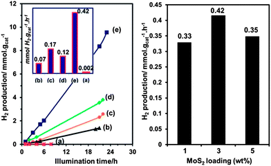 | ||
| Fig. 9 ZnxCd1−xS nanoparticles for HER. ZnxCd1−xS hydrogen photogeneration under visible light irradiation in 0.35 M Na2S + 0.25 M Na2SO3 solution. (left) ZnxCd1−xS–MoS2 3% hybrid photocatalysts: (a) control sample of Zn0.2Cd0.8S without MoS2, (b) x = 0.8, (c) x = 0.6, (d) x = 0.4 and (e) x = 0.2. (right) Zn0.2Cd0.8S with different MoS2 loadings. Reprinted with permission from ref. 62, Copyright 2013 Royal Society of Chemistry. | ||
In 2013, ZnxCd1−xS nanoparticles were used for HER without a co-catalyst.97 The ZnxCd1−xS particles were mixed with carbon nanotubes (CNTs) and allowed to react in an autoclave at 140 °C for 12 h followed by Ar purging for 10 minutes.97 H2 generation was tested in aqueous Na2S + Na2SO3 (Fig. 10). Overall, the ZnxCd1−xS particles with CNT has higher rates of production (1.5×) compared to the non-CNT material. It was determined that the rate of production was heavily influenced by the Cd amount, with the Zn0.83Cd0.17S being the best solid solution (6.03 mmol h−1 g−1). (Note: this result cannot be quantitatively compared with noble metal catalysts such as Pt, as the Pt electrocatalyzed reaction is heavily dependent on the applied potential, which affects the rate of evolution of hydrogen). A possible reaction mechanism was proposed: electrons excited from the S 3p valence band to the metal C-band (hybrid of the Cd 5s5p and Zn 4s4p), creating a hole in the S valence band. The smaller bandgap of the CNT allows the electron transfer to the CNT, followed by the reduction of H+ ions to H2. Lastly, the sulfur ions consume the electron holes in the ZnxCd1−xS.97 It is interesting that hydrogen generation is maximum at a high Zn content (x > 0.75), both with and without CNTs.
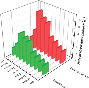 | ||
| Fig. 10 ZnxCd1−xS nanomaterials for HER. The rate of H2 evolution on ZnxCd1−xS and ZnxCd1−xS/CNTs photocatalysts in sulfide/sulfite solution. Reprinted with permission from ref. 97, Copyright 2013 Royal Society of Chemistry. | ||
It's important to note that the XRD results showed that all of these nanoparticles were not a mixture of CdS and ZnS, but a solid solution.97,98,100 This implies that additional structuring of the cations through CTNMs could lead to modified properties (e.g., tunable bandgap).
This synergistic relationship between particles and substrate was demonstrated using MnCo2O4 nanoparticles supported on nitrogen-reduced graphene oxide, which was shown to have good ORR activity and high stability in alkaline solution (Fig. 11).102 Unlike Pt which is known to strongly adsorb anions (e.g. OH−)103 in the same potential region that ORR occurs, metal oxides are not as prone to adsorbates. XRD results showed that Mn was substituted for the Co in the crystal lattice. Energy Dispersive Spectroscopy (EDS) and XPS results confirmed the Mn![[thin space (1/6-em)]](https://www.rsc.org/images/entities/char_2009.gif) :
:![[thin space (1/6-em)]](https://www.rsc.org/images/entities/char_2009.gif) Co ratio of 1
Co ratio of 1![[thin space (1/6-em)]](https://www.rsc.org/images/entities/char_2009.gif) :
:![[thin space (1/6-em)]](https://www.rsc.org/images/entities/char_2009.gif) 2 coupled with ∼4% N in the graphene structure.
2 coupled with ∼4% N in the graphene structure.
The catalyst loading was kept to ∼20% wt: higher loading will result in insulating behavior and no electrochemical reaction. The Mn doped catalyst was compared with other Co oxides such as Co3O4 and CoO. It was found that the Mn-based catalyst has higher activity for ORR evidenced by the oxide peak being the most positively shifted (Fig. 11a). When comparing the ORR curves of MnCo2O4 and Pt, the behavior is almost identical, with the E1/2 of each catalyst being only 0.02 V apart. However, Pt does have the slightly higher half-width potential of the two catalysts (Fig. 11b,c). Rotating Ring Disk Electrode (RRDE) results show that the MnCo2O4 particles reduce oxygen via a 4e-pathway, which is the preferred pathway since the 2e-pathway produces the HO2− intermediate in alkaline solution. Chronoamperometric results indicated a higher tolerance for ORR compared to Pt nanoparticles, with the MnCo2O4 retaining 97% activity compared to 60% activity for Pt after 20![[thin space (1/6-em)]](https://www.rsc.org/images/entities/char_2009.gif) 000 seconds (Fig. 11d). The Mn-based catalyst shows the same catalytic activity towards ORR as Pt nanoparticles, but with much higher stability, making this a good candidate for an alkaline fuel cell cathode.
000 seconds (Fig. 11d). The Mn-based catalyst shows the same catalytic activity towards ORR as Pt nanoparticles, but with much higher stability, making this a good candidate for an alkaline fuel cell cathode.
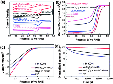 | ||
| Fig. 11 MnCo2O4 nanoparticles obtained for ORR. (a) CV curves of MnCo2O4 hybrid, MnCo2O4 mixture, Co3O4 hybrid, and N-rmGO (nitrogen reduced graphene oxide) catalysts on glassy carbon (GC) electrodes (Pt ORR peak represented by dashed line). Solution: O2 saturated (solid line) or N2-saturated (dash line) 1 M KOH. (b) Rotating-disk electrode curves of MnCo2O4 hybrid, MnCo2O4 mixture, Co3O4 hybrid, N-rmGO, and Pt nanoparticles (Pt/C) on carbon fiber paper electrodes. Scan rate: 5 mV s−1 Rotation rate: 1600 rpm. (c) ORR polarization curves of MnCo2O4 hybrid, Co3O4 hybrid, and Pt/C on carbon fiber papers solution: 1 M KOH. (d) Chronoamperometric curves at 0.70 V vs. RHE for MnCo2O4 hybrid, MnCo2O4 mixture, and Pt nanoparticles (Pt/C) on carbon fiber paper electrodes. Solution: O2 saturated 1 M KOH. Adapted with permission from ref. 102, Copyright 2012 American Chemical Society. | ||
4.2. Li-ion battery
Fig. 12 shows the charge–discharge curves for the nanotubes. As with most battery anode materials the initial charge–discharge rates can be discounted due to solvent degradation. The second set of curves show a discharge of 513.7 mA h g−1 and a charge of 451 mA h g−1, which is a columbic efficiency of 87.8%. While the initial charging–discharging rate is not exceptionally high, the retention of charge with the number of cycles indicates good stability. The durability was assessed with cycling results show that nanotubes are stable for 60 cycles with only a minimal loss of capacitance.
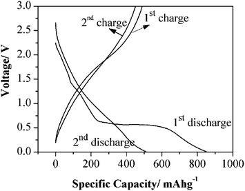 | ||
| Fig. 12 TiOF2 nanotubes in Li-ion battery electrodes. The first two charge–discharge profiles of TiOF2 nanotubes. Current density: 400 mA g−1. The measurements were conducted with a potential window of 0.005–3.0 V. Reprinted with permission from ref. 105, Copyright 2012 Wiley. | ||
![[thin space (1/6-em)]](https://www.rsc.org/images/entities/char_2009.gif) :
:![[thin space (1/6-em)]](https://www.rsc.org/images/entities/char_2009.gif) 0.9
0.9![[thin space (1/6-em)]](https://www.rsc.org/images/entities/char_2009.gif) :
:![[thin space (1/6-em)]](https://www.rsc.org/images/entities/char_2009.gif) 1.9 was the Cu
1.9 was the Cu![[thin space (1/6-em)]](https://www.rsc.org/images/entities/char_2009.gif) :
:![[thin space (1/6-em)]](https://www.rsc.org/images/entities/char_2009.gif) In
In![[thin space (1/6-em)]](https://www.rsc.org/images/entities/char_2009.gif) :
:![[thin space (1/6-em)]](https://www.rsc.org/images/entities/char_2009.gif) S ratio.
S ratio.
Fig. 13 (top) shows charge–discharge curves for the CuInS2 nanospheres. The second and third cycles are within 85% of each other based upon examination of the charge–discharge curves as the discharging capacities for the second and third cycles are 1004 and 903 mA h g−1. Fig. 13 (bottom) shows the cycling performance of the nanospheres. Of interest is that the hollow spheres have improved stability in their specific capacity (charge–discharge) after the first 10 cycles and this is maintained over the course of 20 cycles with an initial loss of over 50% specific activity.
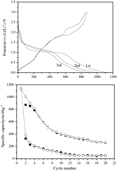 | ||
| Fig. 13 CuInS2 nanospheres obtained in Li-ion battery electrodes. (top) Charge–discharge curves for the first three cycles for the CuInS2 hollow nanospheres. Current density: 30 mA g−1 (bottom) Specific capacity versus cycle number for charge (filled) and discharge (open) on the CuInS2 hollow nanospheres (■,□) and nanoparticles (●,○). Current density: 30 mA g−1 between 3 and 0.005 V. Adapted with permission from ref. 106, Copyright 2012 Elsevier. | ||
Fig. 14 shows the charge–discharge data for the Li1.2Mn0.6−0.5xNi0.2−0.5xCoxO2 cathode material. It is interesting that increasing the Co concentration first increases then decreases the discharge capacity, as well as the charge capacity. The maximum is reached at x = 0.06, with the discharge being ∼230 mA h g−1. The plateau length of the discharge region decreases with increasing Co concentration due to the overlap of the Co+3/+4 t2g and O 2p electron overlap (Fig. 14). Finally, the cycling performance of the material showed ∼10% capacity drop for 40 cycles.
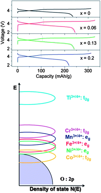 | ||
| Fig. 14 Li1.2Mn0.6−0.5xNi0.2−0.5xCoxO2 particles in Li-ion battery electrodes. (top) First charge–discharge curves for the Li1.2Mn0.6−0.5xNi0.2−0.5xCoxO2 nanoparticles at C/25 rate with a potential window of 2 to 4.5 V. (bottom) Qualitative energy diagram depicting the positions of metal 3d bands with respect to the top of the O2 2p band. Adapted with permission from ref. 108, Copyright 2012 Royal Society of Chemistry. | ||
5. Future work – proposed new systems
As has been seen in the previous sections, non-metallic metastable nanomaterials and chemically transformed nanomaterials have a proven worth in energy applications. The shortfall in this field, however, is the paucity of work specifically examining metastable materials that result from partial chemical transformation reactions (e.g., partial ionic exchanges). Partial reactions during CTNMs can yield interesting metastable intermediates that could impart additional functionality upon the materials. In this section we propose new systems that could be formed by CTNMs, with potential battery and catalysis benefits as metastable phases.In the ORR, both CoO93,101 and Co3S4109,110 are useful catalysts. Cobalt sulfide is used in acidic media which is too harsh for metal oxides, but the cobalt oxide is an overall better catalyst. To this end, a metastable CoxOyS4−y structure (either graded core–shell or a single mixed phase) should be durable enough for acidic solution but have the higher activity of cobalt oxide.
Combinations of metal oxides could be useful as catalysts for the ORR reaction. For example, Co3O4,76–78 Fe3O4,111 and Mn3O4112 are all catalysts and have been significantly tested in alkaline solutions. The Fe based nanoparticles have similar activity but shifted half width potential to more negative potentials compared to Co3O4, and have higher durability than Pt. The Mn nanomaterials however, have slightly higher current densities than the Co-based catalysts. Metastable mixtures of FexMn3−xO4 and CoxMn3−xO4 (where x does not equal 1or 2)102,113 would combine the durability of Fe, the activity of Mn with the high activities/durability of Co and Mn catalysts. This would also allow for characterization in alkaline media.
It is well documented that PtRu114,115 alloys have high catalytic capabilities. Ru chalcogenide compounds have also garnered attention for ORR reactions, specifically RuSe116 and RuSe2,117 because they are stable in acidic solution and also because RuSe2 has a comparable half width potential to Pt (within 0.1 V). A proposed metastable material that could be accessed through chemical transformations of nanomaterials that would be an attractive catalyst is RuxCo3−xSeyO4−y, due to the durability in acidic solution from the selenide content coupled with activity from both Ru and Co.
For Li-ion battery anodes materials Co–CoO,118 CoO,119,120 Co3S4,110 and Co3O489–91,121–125 have been researched. The Co–CoO structure has a slightly higher stability, but Co3O4 has higher theoretical capacity.118 As an illustration of the activity/stability of cobalt chalcogenides, it has been reported that Co3O4 coupled with reduced graphene oxide has a 71% capacity retention during cycling.124 A metastable material such as CoxOy or graded core–shell CoO–Co3O4 could possess both the stability and durability of both parent phases.
Fe3O4126 and FeO127 have also been tested as anode materials for Li-ion batteries, with the FeO having high cycling performance (higher columbic efficiency) compared to Fe3O4 nanoparticles and overall better performance than CoO or Co3O4. The mixed phases of FexCo1−xO and FexCo3−xO4 should be of interest since the Co materials have higher charging capacities than the Fe oxides, but the Fe oxides are more stable. Also, because of the high efficiency of metal sulfides, materials such as FexCo3−xS4 and Co3SyO4−y would also be worthy of attention, combining the stability of the sulfides and the oxide activities.
Cathodic materials for Li batteries continue to be the focus of research, with LiFePO482–87,128 being among the most well-studied materials. In addition, variations of LiFePO4 such as Li2FeSiO4129 and LiMn2−xMoxO4130 have been recently tested with the silicon containing material having high stability under cycling conditions and comparable capacity to LiFePO4. The Mo nanomaterial has lower stability than the Si material and comparable capacity. While most work has been on Li metal oxides, metal sulfides have long been known to be excellent cathodes with TiS294,131 being well-studied. Other metal sulfides such as MoS2132,133 have been accruing interest as Li battery anodes. MoS2 have shown comparable in capacity to the previously listed oxides but does not easily oxidize at the high potentials of battery applications,132 although LiMn2−xMoxO4 and MoS2 are cathodic in nature. To this end, a focus on materials such as MnxMo1−xS2, LiMnMoS4, and TixMo1−xS2 would combine the conductivity of Mo, the stability of Mn, and the activity of Ti.
6. Summary
Chemical transformation of nanomaterials is a young field of research that has provided access to new and exotic nanomaterials. Previous work has shown that the CTNMs method can create metastable materials that have unique electronic, optical, and plasmonic properties. In this highlight review we have shown prominent examples of materials synthesized via CTNMs that are useful for energy applications. We have also pointed to some candidate metastable materials which have high activities/durability for HER, ORR and Li-ion battery technology and could be engineered through CTNMs. Lastly, we have proposed new materials based upon CTNMs that could yield next generation HER and ORR catalysts, and Li-ion batteries. CTNMs could open a new frontier in nanosynthetic chemistry for energy applications by allowing access of nanomaterials that have both unique electronic and stability properties.Acknowledgements
This work was supported in part by the National Science Foundation under award number CHE-1152922, and the Cornell Center for Materials Research (CCMR) with funding from the Materials Research Science and Engineering Center program of the National Science Foundation (cooperative agreement DMR-1120296). R.D.R. was supported as part of the Energy Materials Center at Cornell (EMC2), an Energy Frontier Research Center funded by the U.S. Department of Energy, Office of Science, Office of Basic Energy Science under Award number DE-SC0001086.References
- D. H. Son, S. M. Hughes, Y. D. Yin and A. P. Alivisatos, Science, 2004, 306, 1009–1012 CrossRef CAS PubMed.
- Y. D. Yin, R. M. Rioux, C. K. Erdonmez, S. Hughes, G. A. Somorjai and A. P. Alivisatos, Science, 2004, 304, 711–714 CrossRef CAS PubMed.
- R. D. Robinson, B. Sadtler, D. O. Demchenko, C. K. Erdonmez, L. W. Wang and A. P. Alivisatos, Science, 2007, 317, 355–358 CrossRef CAS PubMed.
- H. J. Fan, U. Gosele and M. Zacharias, Small, 2007, 3, 1660–1671 CrossRef CAS PubMed.
- A. Cabot, V. F. Puntes, E. Shevchenko, Y. Yin, L. Balcells, M. A. Marcus, S. M. Hughes and A. P. Alivisatos, J. Am. Chem. Soc., 2007, 129, 10358–10630 CrossRef CAS PubMed.
- D. O. Demchenko, R. D. Robinson, B. Sadtler, C. K. Erdonmez, A. P. Alivisatos and L. W. Wang, ACS Nano, 2008, 2, 627–636 CrossRef CAS PubMed.
- J. M. Pietryga, D. J. Werder, D. J. Williams, J. L. Casson, R. D. Schaller, V. I. Klimov and J. A. Hollingsworth, J. Am. Chem. Soc., 2008, 130, 4879–4885 CrossRef CAS PubMed.
- A. Cabot, R. K. Smith, Y. D. Yin, H. M. Zheng, B. M. Reinhard, H. T. Liu and A. P. Alivisatos, ACS Nano, 2008, 2, 1452–1458 CrossRef CAS PubMed.
- A. Cabot, M. Ibanez, P. Guardia and A. P. Alivisatos, J. Am. Chem. Soc., 2009, 131, 11326–11328 CrossRef CAS PubMed.
- B. Sadtler, D. O. Demchenko, H. Zheng, S. M. Hughes, M. G. Merkle, U. Dahmen, L. W. Wang and A. P. Alivisatos, J. Am. Chem. Soc., 2009, 131, 5285–5293 CrossRef CAS PubMed.
- J. Park, H. Zheng, Y.-w. Jun and A. P. Alivisatos, J. Am. Chem. Soc., 2009, 131, 13943–13945 CrossRef CAS PubMed.
- J. M. Luther, H. M. Zheng, B. Sadtler and A. P. Alivisatos, J. Am. Chem. Soc., 2009, 131, 16851–16857 CrossRef CAS PubMed.
- P. K. Jain, L. Amirav, S. Aloni and A. P. Alivisatos, J. Am. Chem. Soc., 2010, 132, 9997–9999 CrossRef CAS PubMed.
- J. T. Zhang, Y. Tang, K. Lee and O. Y. Min, Science, 2010, 327, 1634–1638 CrossRef CAS PubMed.
- D. V. Talapin and Y. D. Yin, J. Mater. Chem., 2011, 21, 11454–11456 RSC.
- G. D. Moon, S. Ko, Y. Min, J. Zeng, Y. N. Xia and U. Jeong, Nano Today, 2011, 6, 186–203 CrossRef CAS.
- M. Ibanez, J. D. Fan, W. H. Li, D. Cadavid, R. Nafria, A. Carrete and A. Cabot, Chem. Mater., 2011, 23, 3095–3104 CrossRef CAS.
- E. R. Essinger-Hileman, D. DeCicco, J. F. Bondi and R. E. Schaak, J. Mater. Chem., 2011, 21, 11599–11604 RSC.
- K. Miszta, D. Dorfs, A. Genovese, M. R. Kim and L. Manna, ACS Nano, 2011, 5, 7176–7183 CrossRef CAS PubMed.
- H. B. Li, M. Zanella, A. Genovese, M. Povia, A. Falqui, C. Giannini and L. Manna, Nano Lett., 2011, 11, 4964–4970 CrossRef CAS PubMed.
- D. Mocatta, G. Cohen, J. Schattner, O. Millo, E. Rabani and U. Banin, Science, 2011, 332, 77–81 CrossRef CAS PubMed.
- M. Casavola, M. A. van Huis, S. Bals, K. Lambert, Z. Hens and D. Vanmaekelbergh, Chem. Mater., 2012, 24, 294–302 CrossRef CAS.
- A. Sahu, M. S. Kang, A. Kompch, C. Notthoff, A. W. Wills, D. Deng, M. Winterer, C. D. Frisbie and D. J. Norris, Nano Lett., 2012, 12, 2587–2594 CrossRef CAS PubMed.
- H. Zhang, L. V. Solomon, D.-H. Ha, S. Honrao, R. G. Hennig and R. D. Robinson, Dalton Trans., 2013, 42, 12596–12599 RSC.
- J. A. Medford, A. C. Johnston-Peck and J. B. Tracy, Nanoscale, 2013, 5, 155–159 RSC.
- J. W. Wang, A. C. Johnston-Peck and J. B. Tracy, Chem. Mater., 2009, 21, 4462–4467 CrossRef CAS.
- J. G. Railsback, A. C. Johnston-Peck, J. W. Wang and J. B. Tracy, ACS Nano, 2010, 4, 1913–1920 CrossRef CAS PubMed.
- C. D. Donega, Chem. Soc. Rev., 2011, 40, 1512–1546 RSC.
- D.-H. Ha, L. M. Moreau, C. R. Bealing, H. Zhang, R. G. Hennig and R. D. Robinson, J. Mater. Chem., 2011, 21, 11498–11510 RSC.
- D.-H. Ha, L. M. Moreau, S. Honrao, R. G. Hennig and R. D. Robinson, J. Phys. Chem. C, 2013, 117, 14303 CAS.
- V. A. Vlaskin, C. J. Barrows, C. S. Erickson and D. R. Gamelin, J. Am. Chem. Soc., 2013, 135, 14380 CrossRef CAS PubMed.
- J. Maier, Phys. Chem. Chem. Phys., 2009, 11, 3011–3022 RSC.
- J. Maier, Adv. Mater., 2009, 21, 2571–2585 CrossRef CAS.
- V. R. Stamenkovic, B. Fowler, B. S. Mun, G. Wang, P. N. Ross, C. A. Lucas and N. M. Markovic, Science, 2007, 315, 493–497 CrossRef CAS PubMed.
- R. Ghosh Chaudhuri and S. Paria, Chem. Rev., 2011, 112, 2373–2433 CrossRef PubMed.
- D. Wang, H. L. Xin, R. Hovden, H. Wang, Y. Yu, D. A. Muller, F. J. DiSalvo and H. D. Abruna, Nat. Mater., 2013, 12, 81–87 CrossRef CAS PubMed.
- F. Stellacci, Nat. Mater., 2005, 4, 113–114 CrossRef CAS PubMed.
- M. H. Oh, T. Yu, S.-H. Yu, B. Lim, K.-T. Ko, M.-G. Willinger, D.-H. Seo, B. H. Kim, M. G. Cho, J.-H. Park, K. Kang, Y.-E. Sung, N. Pinna and T. Hyeon, Science, 2013, 340, 964–968 CrossRef CAS PubMed.
- U. Jeong and Y. Xia, Angew. Chem., Int. Ed., 2005, 44, 3099–3103 CrossRef CAS PubMed.
- J. M. Buriak, Science, 2004, 304, 692–693 CrossRef CAS PubMed.
- J. B. Rivest and P. K. Jain, Chem. Soc. Rev., 2013, 42, 89–96 RSC.
- Diffusivities were calculated from the Arrhenius equation (D = D0e(−E/RT)) using the activation energy and diffusion coefficients from ref. 8. The temperature was set at room temperature (293.15 K).
- Time was calculated using the equation 〈x〉2 = qiDt, where the mean free path is the square of nanometer dimensions (x = 10−7 cm) or bulk dimensions (x = 0.1 cm). qi was set at 6, in order to allow for a comparison in 3 − D, while D was resultant from ref. 42.
- E. M. Chan, M. A. Marcus, S. Fakra, M. ElNaggar, R. A. Mathies and A. P. Alivisatos, J. Phys. Chem. A, 2007, 111, 12210–12215 CrossRef CAS PubMed.
- P. K. Jain, B. J. Beberwyck, L.-K. Fong, M. J. Polking and A. P. Alivisatos, Angew. Chem., Int. Ed. Engl., 2012, 124, 2437–2440 CrossRef.
- H. L. Cao, X. F. Qian, C. Wang, X. D. Ma, J. Yin and Z. K. Zhu, J. Am. Chem. Soc., 2005, 127, 16024–16025 CrossRef CAS PubMed.
- L. Dloczik and R. Könenkamp, Nano Lett., 2003, 3, 651–653 CrossRef CAS.
- J. Geng, B. Liu, L. Xu, F.-N. Hu and J.-J. Zhu, Langmuir, 2007, 23, 10286–10293 CrossRef CAS PubMed.
- F. Dawood and R. E. Schaak, J. Am. Chem. Soc., 2008, 131, 424–425 CrossRef PubMed.
- Q. H. Zhang and L. Gao, J. Am. Ceram. Soc., 2006, 89, 415–421 CrossRef CAS.
- X. Wang, S. Li, H. Yu and J. Yu, J. Mol. Catal. A: Chem., 2011, 334, 52–59 CrossRef CAS.
- A. W. Cohn, K. R. Kittilstved and D. R. Gamelin, J. Am. Chem. Soc., 2012, 134, 7937–7943 CrossRef CAS PubMed.
- B. D. Mao, C. H. Chuang, F. Lu, L. X. Sang, J. J. Zhu and C. Burda, J. Phys. Chem. C, 2013, 117, 648–656 CAS.
- A. Grubisic, E. Ringe, C. M. Cobley, Y. Xia, L. D. Marks, R. P. Van Duyne and D. J. Nesbitt, Nano Lett., 2012, 12, 4823–4829 CrossRef CAS PubMed.
- I. Kriegel, J. Rodriguez-Fernandez, A. Wisnet, H. Zhang, C. Waurisch, A. Eychmueller, A. Dubavik, A. O. Govorov and J. Feldmann, ACS Nano, 2013, 7, 4367–4377 CrossRef CAS PubMed.
- N. M. Markovic, B. N. Grgur and P. N. Ross, J. Phys. Chem. B, 1997, 101, 5405–5413 CrossRef CAS.
- N. M. Markovic, C. A. Lucas, V. Climent, V. Stamenkovic and P. N. Ross, Surf. Sci., 2000, 465, 103–114 CrossRef CAS.
- V. Stamenkovic, N. M. Markovic and P. N. Ross Jr, J. Electroanal. Chem., 2001, 500, 44–51 CrossRef CAS.
- T. J. Schmidt, P. N. Ross and N. M. Markovic, J. Electroanal. Chem., 2002, 524, 252–260 CrossRef.
- L. Kibler, Electrochim. Acta, 2008, 53, 6824–6828 CrossRef CAS.
- Z. Chen, D. Cummins, B. N. Reinecke, E. Clark, M. K. Sunkara and T. F. Jaramillo, Nano Lett., 2011, 11, 4168–4175 CrossRef CAS PubMed.
- M. Nguyen, P. D. Tran, S. S. Pramana, R. L. Lee, S. K. Batabyal, N. Mathews, L. H. Wong and M. Graetzel, Nanoscale, 2013, 5, 1479–1482 RSC.
- M. A. Lukowski, A. S. Daniel, F. Meng, A. Forticaux, L. Li and S. Jin, J. Am. Chem. Soc., 2013, 135, 10274–10277 CrossRef CAS PubMed.
- E. Antolini, Mater. Chem. Phys., 2003, 78, 563–573 CrossRef CAS.
- V. Stamenković, T. J. Schmidt, P. N. Ross and N. M. Marković, J. Electroanal. Chem., 2003, 554–555, 191–199 CrossRef.
- Y. Liu, C. M. Hangarter, U. Bertocci and T. P. Moffat, J. Phys. Chem. C, 2012, 116, 7848–7862 CAS.
- K. Uosaki, S. Ye, H. Naohara, Y. Oda, T. Haba and T. Kondo, J. Phys. Chem. B, 1997, 101, 7566–7572 CrossRef CAS.
- S. R. Brankovic, J. X. Wang and R. R. Adzic, Surf. Sci., 2001, 474, L173–L179 CrossRef CAS.
- M. F. Mrozek, Y. Xie and M. J. Weaver, Anal. Chem., 2001, 73, 5953–5960 CrossRef CAS PubMed.
- J. Zhang, Y. Mo, M. B. Vukmirovic, R. Klie, K. Sasaki and R. R. Adzic, J. Phys. Chem. B, 2004, 108, 10955–10964 CrossRef CAS.
- Y. G. Kim, J. Y. Kim, D. Vairavapandian and J. L. Stickney, J. Phys. Chem. B, 2006, 110, 17998–18006 CrossRef CAS PubMed.
- M. Fayette, Y. Liu, D. Bertrand, J. Nutariya, N. Vasiljevic and N. Dimitrov, Langmuir, 2011, 27, 5650–5658 CrossRef CAS PubMed.
- J. Nutariya, M. Fayette, N. Dimitrov and N. Vasiljevic, Electrochim. Acta, 2013 DOI:10.1016/j.electacta.2013.01.052.
- K. Kinoshita, J. Electrochem. Soc., 1990, 137, 845–848 CrossRef CAS.
- S. Guo and S. Sun, J. Am. Chem. Soc., 2012, 134, 2492–2495 CrossRef CAS PubMed.
- Y. Y. Liang, Y. G. Li, H. L. Wang, J. G. Zhou, J. Wang, T. Regier and H. J. Dai, Nat. Mater., 2011, 10, 780–786 CrossRef CAS PubMed.
- J. Xu, P. Gao and T. S. Zhao, Energy Environ. Sci., 2012, 5, 5333–5339 CAS.
- D. Wang, X. Chen, D. G. Evans and W. Yang, Nanoscale, 2013, 5, 5312–5315 RSC.
- X. Y. Wang, X. F. Ren, K. Kahen, M. A. Hahn, M. Rajeswaran, S. Maccagnano-Zacher, J. Silcox, G. E. Cragg, A. L. Efros and T. D. Krauss, Nature, 2009, 459, 686–689 CrossRef CAS PubMed.
- Y. S. Jung, P. Lu, A. S. Cavanagh, C. Ban, G.-H. Kim, S.-H. Lee, S. M. George, S. J. Harris and A. C. Dillon, Adv. Energy Mater., 2013, 3, 213–219 CrossRef CAS.
- Y. Ou, J. Wen, H. Xu, S. Xie and J. Li, J. Phys. Chem. Solids, 2013, 74, 322–327 CrossRef CAS.
- J. Hong, C. S. Wang, X. Chen, S. Upreti and M. S. Whittingham, Electrochem. Solid-State Lett., 2009, 12, A33–A38 CrossRef CAS.
- F. Omenya, N. A. Chernova, S. Upreti, P. Y. Zavalij, K. W. Nam, X. Q. Yang and M. S. Whittingham, Chem. Mater., 2011, 23, 4733–4740 CrossRef CAS.
- J. Hong, X. L. Wang, Q. Wang, F. Omenya, N. A. Chernoya, M. S. Whittingham and J. Graetz, J. Phys. Chem. C, 2012, 116, 20787–20793 CAS.
- S. Upreti, N. A. Chernova, J. Xiao, J. K. Miller, O. V. Yakubovich, J. Cabana, C. P. Grey, V. L. Chevrier, G. Ceder, J. L. Musfeldt and M. S. Whittingham, Chem. Mater., 2012, 24, 166–173 CrossRef CAS.
- F. Omenya, N. A. Chernova, Q. Wang, R. B. Zhang and M. S. Whittingham, Chem. Mater., 2013, 25, 2691–2699 CrossRef CAS.
- F. Omenya, N. A. Chernova, R. B. Zhang, J. Fang, Y. Q. Huang, F. Cohen, N. Dobrzynski, S. Senanayake, W. Q. Xu and M. S. Whittingham, Chem. Mater., 2013, 25, 85–89 CrossRef CAS.
- C.-T. Hsieh, J.-S. Lin, Y.-F. Chen and H. Teng, J. Phys. Chem. C, 2012, 116, 15251–15258 CAS.
- M. Ren, S. Yuan, L. Su and Z. Zhou, Solid State Sci., 2012, 14, 451–455 CrossRef CAS.
- L. Pan, H. Zhao, W. Shen, X. Dong and J. Xu, J. Mater. Chem. A, 2013, 1, 7159–7166 CAS.
- A. K. Rai, J. Gim, L. T. Anh and J. Kim, Electrochim. Acta, 2013, 100, 63–71 CrossRef CAS.
- Y. Shemesh, J. E. Macdonald, G. Menagen and U. Banin, Angew. Chem., Int. Ed., 2011, 50, 1185–1189 CrossRef CAS PubMed.
- S. Guo, S. Zhang, L. Wu and S. Sun, Angew. Chem., Int. Ed., 2012, 51, 11770–11773 CrossRef CAS PubMed.
- M. S. Whittingham, Prog. Solid State Chem., 1978, 12, 41–99 CrossRef CAS.
- R. Cai, J. Chen, J. Zhu, C. Xu, W. Zhang, C. Zhang, W. Shi, H. Tan, D. Yang, H. H. Hng, T. M. Lim and Q. Yan, J. Phys. Chem. C, 2012, 116, 12468–12474 CAS.
- R. Banerjee, R. Jayakrishnan and P. Ayyub, J. Phys.: Condens. Matter, 2000, 12, 10647 CrossRef CAS.
- L. Wang, Z. Yao, F. Jia, B. Chen and Z. Jiang, Dalton Trans., 2013, 42, 9976–9981 RSC.
- W. Wang, W. Zhu and H. Xu, J. Phys. Chem. C, 2008, 112, 16754–16758 CAS.
- C. Xing, Y. Zhang, W. Yan and L. Guo, Int. J. Hydrogen Energy, 2006, 31, 2018–2024 CrossRef CAS.
- X. Xu, R. Lu, X. Zhao, Y. Zhu, S. Xu and F. Zhang, Appl. Catal., B, 2012, 125, 11–20 CrossRef CAS.
- Y. Liang, H. Wang, P. Diao, W. Chang, G. Hong, Y. Li, M. Gong, L. Xie, J. Zhou, J. Wang, T. Z. Regier, F. Wei and H. Dai, J. Am. Chem. Soc., 2012, 134, 15849–15857 CrossRef CAS PubMed.
- Y. Liang, H. Wang, J. Zhou, Y. Li, J. Wang, T. Regier and H. Dai, J. Am. Chem. Soc., 2012, 134, 3517–3523 CrossRef CAS PubMed.
- N. M. Marković, T. J. Schmidt, V. Stamenković and P. N. Ross, Fuel Cells, 2001, 1, 105–116 CrossRef.
- N. Li, G. Liu, C. Zhen, F. Li, L. Zhang and H.-M. Cheng, Adv. Funct. Mater., 2011, 21, 1717–1722 CrossRef CAS.
- Y. Zeng, W. Zhang, C. Xu, N. Xiao, Y. Huang, D. Y. W. Yu, H. H. Hng and Q. Yan, Chem.–Eur. J., 2012, 18, 4026–4030 CrossRef CAS PubMed.
- W. Zhang, H. Zeng, Z. Yang and Q. Wang, J. Solid State Chem., 2012, 186, 58–63 CrossRef CAS.
- X. T. Lu, Z. B. Zhuang, Q. Peng and Y. D. Li, CrystEngComm, 2011, 13, 4039–4045 RSC.
- C.-C. Wang and A. Manthiram, J. Mater. Chem. A, 2013, 1, 10209–10217 CAS.
- Y. Feng, T. He and N. Alonso-Vante, Chem. Mater., 2007, 20, 26–28 CrossRef.
- N. Mahmood, C. Zhang, J. Jiang, F. Liu and Y. Hou, Chem.–Eur. J., 2013, 19, 5183–5190 CrossRef CAS PubMed.
- Z.-S. Wu, S. Yang, Y. Sun, K. Parvez, X. Feng and K. Müllen, J. Am. Chem. Soc., 2012, 134, 9082–9085 CrossRef CAS PubMed.
- Y. Gorlin, C.-J. Chung, D. Nordlund, B. M. Clemens and T. F. Jaramillo, ACS Catal., 2012, 2, 2687–2694 CrossRef CAS.
- H. Zhu, S. Zhang, Y.-X. Huang, L. Wu and S. Sun, Nano Lett., 2013, 13, 2947–2951 CrossRef CAS PubMed.
- N. M. Markovic, H. A. Gasteiger, P. N. Ross Jr, X. Jiange, I. Villegas and M. J. Weaver, Electrochim. Acta, 1995, 40, 91–98 CrossRef CAS.
- J.-H. Choi, K.-J. Jeong, Y. Dong, J. Han, T.-H. Lim, J.-S. Lee and Y.-E. Sung, J. Power Sources, 2006, 163, 71–75 CrossRef CAS.
- A. Ezeta-Mejía, O. Solorza-Feria, H. J. Dorantes-Rosales, J. M. H. López and E. M. Arce-Estrada, Int. J. Electrochem. Sci., 2012, 7, 8940–8957 Search PubMed.
- P. H. C. Camargo, Z. Peng, X. Lu, H. Yang and Y. Xia, J. Mater. Chem., 2009, 19, 1024–1030 RSC.
- L. Zhang, P. Hu, X. Zhao, R. Tian, R. Zou and D. Xia, J. Mater. Chem., 2011, 21, 18279–18283 RSC.
- X. Zheng, G. Shen, Y. Li, H. Duan, X. Yang, S. Huang, H. Wang, C. Wang, Z. Deng and B.-L. Su, J. Mater. Chem. A, 2013, 1, 1394–1400 CAS.
- W.-H. Ryu, J. Shin, J.-W. Jung and I.-D. Kim, J. Mater. Chem. A, 2013, 1, 3239–3243 CAS.
- R. Yang, Z. Wang, J. Liu and L. Chen, Electrochem. Solid-State Lett., 2004, 7, A496–A499 CrossRef CAS.
- G. Wang, J. Liu, S. Tang, H. Li and D. Cao, J. Solid State Electrochem., 2011, 15, 2587–2592 CrossRef CAS.
- H. Duliang, W. Jun, T. Fei, C. Mindong, W. Yong, D. D. Meng and L. Guiqing, Micro Nano Lett., 2012, 7, 773–777 Search PubMed.
- B. G. Choi, S.-J. Chang, Y. B. Lee, J. S. Bae, H. J. Kim and Y. S. Huh, Nanoscale, 2012, 4, 5924–5930 RSC.
- X. W. Lou, D. Deng, J. Y. Lee, J. Feng and L. A. Archer, Adv. Mater., 2008, 20, 258–262 CrossRef CAS.
- B. Das, M. V. Reddy and B. V. R. Chowdari, J. Alloys Compd., 2013, 565, 90–96 CrossRef CAS.
- M. Gao, P. Zhou, P. Wang, J. Wang, C. Liang, J. Zhang and Y. Liu, J. Alloys Compd., 2013, 565, 97–103 CrossRef CAS.
- Y. Lin, Y. Lin, T. Zhou, G. Zhao, Y. Huang, Y. Yang and Z. Huang, Mater. Chem. Phys., 2013, 138, 313–318 CrossRef CAS.
- X. Wu, X. Wang and Y. Zhang, ACS Appl. Mater. Interfaces, 2013, 5, 2510–2516 CAS.
- S. Jayapal, R. Mariappan and S. Piraman, J. Solid State Electrochem., 2013, 17, 2157–2165 CrossRef CAS.
- G. Che, K. B. Jirage, E. R. Fisher, C. R. Martin and H. Yoneyama, J. Electrochem. Soc., 1997, 144, 4296–4302 CrossRef CAS.
- X. Fang, C. Hua, X. Guo, Y. Hu, Z. Wang, X. Gao, F. Wu, J. Wang and L. Chen, Electrochim. Acta, 2012, 81, 155–160 CrossRef CAS.
- J.-Z. Wang, L. Lu, M. Lotya, J. N. Coleman, S.-L. Chou, H.-K. Liu, A. I. Minett and J. Chen, Adv. Energy Mater., 2013, 3, 798–805 CrossRef CAS.
| This journal is © The Royal Society of Chemistry 2014 |


