
 Open Access Article
 This Open Access Article is licensed under a
 Creative Commons Attribution 3.0 Unported Licence
Magnetic field induced quantum dot brightening in liquid crystal synergized magnetic and semiconducting nanoparticle composite assemblies
Jose Jussi
Amaral
,
Jacky
Wan
,
Andrea L.
Rodarte
,
Christopher
Ferri
,
Makiko T.
Quint
,
Ronald J.
Pandolfi
,
Michael
Scheibner
,
Linda S.
Hirst
* and
Sayantani
Ghosh
*
Physics, School of Natural Sciences, University of California, 5200 N. Lake Rd, Merced CA 95343, USA. E-mail: lhirst@ucmerced.edu; sghosh@ucmerced.edu
First published on 22nd October 2014
Abstract
The design and development of multifunctional composite materials from artificial nano-constituents is one of the most compelling current research areas. This drive to improve over nature and produce ‘meta-materials’ has met with some success, but results have proven limited with regards to both the demonstration of synergistic functionalities and in the ability to manipulate the material properties post-fabrication and in situ. Here, magnetic nanoparticles (MNPs) and semiconducting quantum dots (QDs) are co-assembled in a nematic liquid crystalline (LC) matrix, forming composite structures in which the emission intensity of the quantum dots is systematically and reversibly controlled with a small applied magnetic field (<100 mT). This magnetic field-driven brightening, ranging between a two- to three-fold peak intensity increase, is a truly cooperative effect: the LC phase transition creates the co-assemblies, the clustering of the MNPs produces LC re-orientation at atypical low external field, and this re-arrangement produces compaction of the clusters, resulting in the detection of increased QD emission. These results demonstrate a synergistic, reversible, and an all-optical process to detect magnetic fields and additionally, as the clusters are self-assembled in a fluid medium, they offer the possibility for these sensors to be used in broad ranging fluid-based applications.
Introduction
Nanoparticles (NPs) exhibit unique electronic, magnetic and optical properties arising from quantum confinement that distinguish them from the constituent bulk materials.1 These properties, coupled with a large diversity in composition and morphology, have made NPs some of the most widely used materials in a variety of applications, which include optoelectronics, biomedicine, food processing, and renewable energy.2,3 A relatively new development in materials research is the use of NPs as ‘building blocks’ to design superlattices that would form meta-materials with functionalities significantly modified from those of individual constituents.4 The most common approaches include traditional bottom-up assembly of NPs, which has successfully created two- and three-dimensional superlattices with up to three different types of particles and the synthesis of hybrid core–shell composite nanostructures.5–7 These avenues have yielded structurally well-ordered arrays extending over microns, but the functional aspect has been less compelling. Most of the superlattices formed this way tend to simply exhibit the combined properties of the constituent NPs, instead of exhibiting a novel functionality arising from synergistic inter-particle interactions. An alternative route is to use soft materials (polymers, liquid crystals, biomolecules, etc.) as templates for NP assembly,8–11 since long-range crystalline order is not required to observe synergistic functionalities. A soft host would remove rigid constraints in the way the individual components can be combined and make novel architectures possible, such as non-planar structures. Additionally, it would allow in situ modulation of the NP assembly via external controls, such as temperature, mechanical strain and electromagnetic fields, which could lead to greater versatility in functionality or even to the emergence of entirely novel behaviour. In this study, we co-assemble magnetic nanoparticles (MNPs) and semiconducting quantum dots (QDs) in a nematic liquid crystalline (LC) matrix,12 forming composite structures in which we can control the emission intensity of the QDs systematically and reversibly, with the application of a small external magnetic field (<100 mT). Our results demonstrate a synergistic, reversible, and an all-optical process to detect magnetic fields and additionally, as the clusters are self-assembled in a fluid medium, they offer the possibility for these sensors to be used in broad ranging fluid-based applications.Our choice of LC as the host material is motivated by several factors. The LC phases exhibited by a material can be fine-tuned via careful control of molecular structure. LC materials are optically anisotropic and therefore birefringent, which means they can be manipulated to produce macroscopic domains with a defined optical axis. In several LC phases, molecular orientation can be further controlled by external electric and magnetic fields. They are, therefore, ideal materials to form a switchable matrix for dynamic NP assembly.13,14 The multifunctional combination of semiconducting and magnetic materials is a very attractive one with great potential for application in two widely different fields. The first is in the computing/information processing industry, where a magnetic semiconductor could simultaneously handle both data storage and processing. Research efforts in this area continue to make progress,15 but are less focused on colloidal nanomaterials. The second field is biological/biomedical sciences,16,17 where chemically synthesized semiconducting and magnetic NPs are widely used. The high quantum yield of fluorescence and relative optical stability of QDs has made them popular for cellular tagging, imaging, and sensing. In the case of MNPs, their directional response to magnetic field gradients is exploited for cell separation and drug delivery, among other applications. Recently, there has been some preliminary progress in using formulations combining fluorescence and magnetic properties for multimodal imaging.18,19 Our study has significant advantages over these current findings, as it demonstrates a strategy for the self-assembly of densely-packed NP clusters that can be modulated via their electro-optically active host to exhibit synergistic behaviour that is considerably modified from that of the individual particles.
Results and discussions
Assembly and structural characterization of nano-composites
We disperse 6 nm CdSe/ZnS core–shell QDs (ligand: octadecylamine) and 10 nm Fe3O4 MNPs (ligand: oleic acid) in a nematic LC, 4′-pentyl-4-biphenylcarbonitrile (commonly known as 5CB). The QDs emission spectrum is centered at 630 nm in solution with a FWHM (full width at half maximum) of ∼30 nm. The MNPs are optically inactive and paramagnetic at room temperature. 5CB is nematic at room temperature and is used to both facilitate the assembly and stabilize the NP clusters. Fig. 1a shows a series of fluorescence microscopy images demonstrating the temperature evolution of the composite material on cooling, and the subsequent co-assembly of the clusters. When the LC is in the isotropic phase, the NPs form a uniformly mixed, stable dispersion. Cooling at a rate of 0.1 °C min−1 to a temperature below the clearing point (34.4 °C) results in the NPs gradually being excluded into less ordered regions of the LC to minimize the elastic deformation energy cost to the system.12 The final picture is shown in Fig. 1a at 34.1 °C where each bright point is a cluster of NPs. Average cluster size is 10–20 μm and the average separation 50–100 μm, but these values are dependent on the cooling rate and initial QD concentration, with faster rates yielding smaller clusters. Prior studies12 on LC mediated QD assembly suggested that within each cluster the particles are arranged in irregular aggregates, but the inter-dot separation is uniform throughout. The transmission electron microscopy (TEM) image of a QD cluster in Fig. 1b appears to confirm this, where a loose fractal-like NP assembly can be observed. Small angle X-ray scattering (SAXS) results reveal further details about the co-assembly process. | ||
| Fig. 1 (a) 10 nm magnetic Fe3O4 nanoparticles (MNPs) and 6 nm CdSe/ZnS core–shell quantum dots (QDs) dispersed in isotopic liquid crystal (LC), 5CB. As 5CB is cooled through the I–N phase transition, co-assemblies of MNP–QD form in disordered LC regions (b) TEM image of a QD-only assembly formed by the same method, surveyed through the host LC. (c) SAXS results of a series of MNP–QD samples in 5CB, showing the observed diffraction peaks of the scattering vector q varying with the relative ratios of the two NPs. The shorter peak corresponds to 8.9 nm (red circles) and longer peaks to 12.5 nm (black squares). Dashed lines indicate the NP concentration region that allows the best chances of co-assemblies forming (insets). Schematics of co-assembled clusters showing the segregated domains of QDs and MNPs. | ||
Transmission scattering from clusters in the LC phase yields broad diffraction peaks indicative of the average QD–QD separation in the cluster. In Fig. 1c we plot the scattering vector, q, for the observed peaks for a series of samples with varying proportions of QDs and MNPs. For QD-rich and MNP-rich samples, we observe single peaks in q that correspond to 8.9 nm and 12.5 nm NP separations, respectively. These numbers are consistent with expected nearest neighbour distances between close-packed QDs and close-packed MNPs, after accounting for the shell and surface ligand interdigitation. In the range of QD![[thin space (1/6-em)]](https://www.rsc.org/images/entities/char_2009.gif) :MNP ratios of 1–1:2, both of these length scales are present, but there are no indications of a third diffraction peak, or any peak broadening, suggestive of QD–MNP close-packing. These observations lead us to conclude that the different NPs form segregated domains within the clusters. The schematics in Fig. 1c combine the above TEM and SAXS results to depict a possible arrangement within the co-assembled clusters, and we follow up with the functional characterization using photoluminescence (PL) and magneto-optical Kerr effect (MOKE) microscopy.
:MNP ratios of 1–1:2, both of these length scales are present, but there are no indications of a third diffraction peak, or any peak broadening, suggestive of QD–MNP close-packing. These observations lead us to conclude that the different NPs form segregated domains within the clusters. The schematics in Fig. 1c combine the above TEM and SAXS results to depict a possible arrangement within the co-assembled clusters, and we follow up with the functional characterization using photoluminescence (PL) and magneto-optical Kerr effect (MOKE) microscopy.
Synergistic emission enhancement in nano-composites
The PL of a QD ensemble divulges information about almost all fundamental properties, including its size distribution and absence or presence of inter-dot interactions. MNPs are optically inactive and we need to use a different imaging technique. MOKE20 is the rotation upon reflection of the incident linear polarization of an excitation laser beam in response to any optical anisotropy in a sample. We use the polar MOKE configuration, with the magnetic field B applied out-of-plane and the linearly polarized excitation laser in near normal incidence (Fig. 2a). The angle of this rotation is called the Kerr angle, θK. In the case of magnetic materials where the magnetization M imparts anisotropy in permittivity ε, θK ∝ M, and for our collection of paramagnetic NPs, the magnetization follows a linear relation M = χμB (χ: susceptibility, μ: permeability). This linear relation is verified for a drop-cast film of MNPs and shown in Fig. 2b (black triangles), which also shows Kerr rotation from a sample of nematic LC (red circles) for the same range of B. Although not magnetic, the structural anisotropy of LC molecules makes them birefringent, and this makes them responsive to MOKE measurements. At low applied B, this shows up as a constant offset. However, at higher B, analogous to their response to external electric fields, the LC molecules re-orient and the resultant Kerr rotation is plotted in the inset to Fig. 2c. The black arrow defines the critical threshold field Bc for re-orientation. For an LC like 5CB the critical field Bc is high (∼0.5 T) due to its small χ, but theory and experiments have established that on doping with MNPs, this threshold decreases.21,22 In Fig. 2c we plot Bc for 5CB doped with MNPs over a range of concentration Φ, and find that it satisfies the canonical relation Bc ∝ Φ−1/2.23,24 Since we restrict our applied B to <100 mT and MNP concentration less than 0.1% wt, the θK contribution from LC molecules in our samples is magnetic field-independent in the regions away from clusters. However, due to the fact that the local MNP density is far higher in the clusters, in their vicinity, the birefringence change of the disordered LC molecules is larger than expected, as we observe in Fig. 3.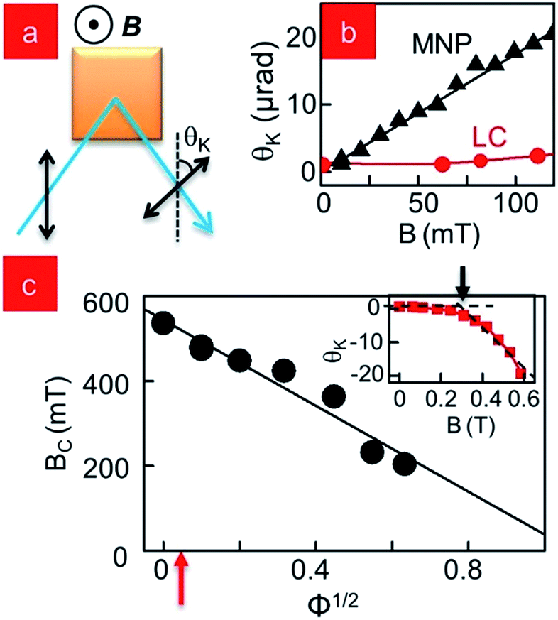 | ||
| Fig. 2 (a) Schematic of the technique of MOKE (b) Kerr angle θK for MNPs and LC molecules at low B (c) (inset) MOKE measurement showing LC switching with B. Arrow denotes the critical switching field Bc. (main) Bc as a function of MNP concentration Φ. Red arrow shows the MNP concentration used specifically for this study. | ||
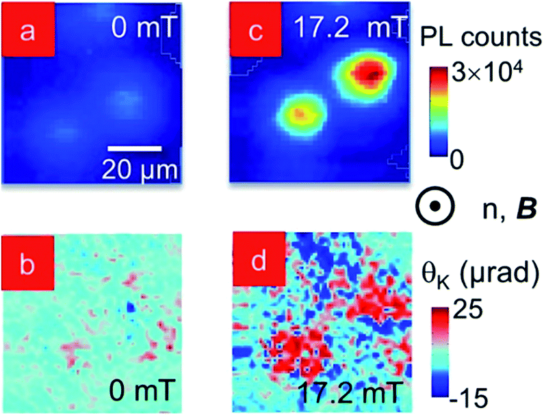 | ||
| Fig. 3 Spatially-resolved PL intensity scan of MNP–QD co-assembly in homeotropically aligned 5CB at (a) 0 and (c) 17.2 mT. Corresponding spatially-resolved MOKE images of the same assemblies at (b) 0 and (d) 17.2 mT. Scale bar in (a) refers to all images. | ||
Fig. 3a and c are spatially-resolved maps of the PL emission intensity and θK of a collection of two neighbouring clusters at B = 0 in a homeotropically aligned LC matrix. PL signal marks the location of QDs in the clusters in Fig. 3a and at positions that correlate to the centers of the PL spots, Fig. 3b shows localized high θK values, indicating the possibility of MNPs in those regions. The remaining area has θK ≠ 0, in spite of the induced homeotropic alignment of the LC, where the molecules should be pointing out-of-plane and not contribute to birefringence for light incident along the same direction. In fact, this is typical as the LC molecules are disordered around the co-assembled clusters and have an approximate radial arrangement in that region. The PL and MOKE scans are repeated over the same spatial region at B = 17.2 mT in Fig. 3c and d. The PL intensity (Fig. 3c) increases between two- to three-fold in the clusters compared to the B = 0 mT data and θK shows a two-fold increase in Fig. 3d. The spatial consistency between PL and MOKE images confirms for the first time that the QDs and MNPs do co-assemble in the clusters. This result is further supported by the SAXS results, validating our schematic in Fig. 1c. The MOKE map also shows areas surrounding the clusters where θK decreases on the application of B. This is the result of the spatial re-orientation of the disordered, and therefore, weakly anchored, LC molecules immediately surrounding the MNP clusters.
Systematic and reversible optical magnetic sensing
We track the PL enhancement with increasing B systematically and plot the PL intensity integrated over the entire scanned region of a cluster in Fig. 4a. The cluster is shown in the inset to the main figure. We observe an initial linear rise that approaches saturation around 80 mT. As a reference, M of the MNP clusters is linear in this regime (Fig. 2b) and do not approach saturation until B > 700 mT. Ensembles of QDs often exhibit spontaneous photo-induced brightening under constant illumination, and we rule out a similar effect by (a) ensuring the excitation power is always extremely low (<18 μW), (b) performing PL scans under identical conditions in control samples with only QDs in LC, and (c) reversing the direction of magnetic field change. We verify the reversibility of this effect in Fig. 4b by taking PL scans at 0, 41.2 mT and 82.5 mT (marked by open circles in Fig. 4a) while ramping the field up, and then again at 41.2 mT and 0 while ramping down. For each iteration of B we allow an equilibration time of 10 min. We note that the PL enhancement is reversible, although slightly hysteretic. | ||
| Fig. 4 (a) (inset) PL intensity map of QD–MNP cluster at 0 and 82.5 mT in planar aligned 5CB (main) spatially-integrated PL intensity of the cluster plotted as a function of increasing applied magnetic field (b) PL intensity maps at magnetic field value indicated by red circles in (a) while ramping up (green arrows, 0 → 82.5 mT) and down (red arrows, 82.5 mT → 0). | ||
This PL enhancement, observed in both homeotropic and planar aligned samples, is very intriguing, as there is no straightforward explanation for the two- to three-fold peak PL enhancement at such low B. We ruled out photo-induced QD brightening, and the only other instance of CdSe QDs exhibiting increased emission intensity with magnetic field occurs at very high B (∼10 T).25 For more information, we plot the peak emission wavelength λP of the QDs in this cluster in Fig. 5a. In an ensemble of densely packed QDs, the smaller dots transfer energy to the larger ones, causing a resultant red-shift of the emission spectrum. This mechanism, known as FRET (Forster resonant energy transfer) is well understood,26 and it allows λP to be used as a ruler to measure inter-dot separation, which in turn reflects the strength of inter-dot coupling. In solution, when the QDs are isolated with no inter-dot interactions, λP = 630 nm, but in Fig. 5a (B = 0) the emission is centered between 635–638 nm, suggesting the QDs are close-packed as evidenced in the SAXS measurement of Fig. 1c. Comparative λP map at B = 82.5 mT shows no significant increase in median λP distribution across the cluster, which suggests the average inter-dot spatial separation remains unchanged and the increased magnetic field does not alter any fundamental inter-particle coupling. SAXS results confirm this result as well. Since it is therefore unlikely that the emission from the individual QDs changes with the application of the field, the net increase in the integrated intensity seen in Fig. 4a over the field of view must come from a corresponding increase in the number of QDs within the imaging volume. A visual inspection of the λP maps does highlight an apparent change in the cluster size, and in Fig. 5b we plot line profiles from the corresponding PL intensity maps (Fig. 4a, inset), and the data confirm a symmetric spatial compression with increasing B. We estimate the percent increase in QDs in the imaging volume from this by evaluating n = 100d/((100 − d)) where d is the measured percent decrease of cluster diameter with B. In Fig. 5c we plot n as a function of B concurrently with the relative change in PL intensity, f, and find that they compare very favourably. By the maximum applied B, f shows a total change of almost 40% in integrated PL emission while the spatial compaction predicts an increase in QD density of 36%, off by a mere four percent. But while these estimates suggest the observed effect is related to a compaction of the clusters, the question that arises is how are the clusters shrinking without decreasing the average inter-dot separation?
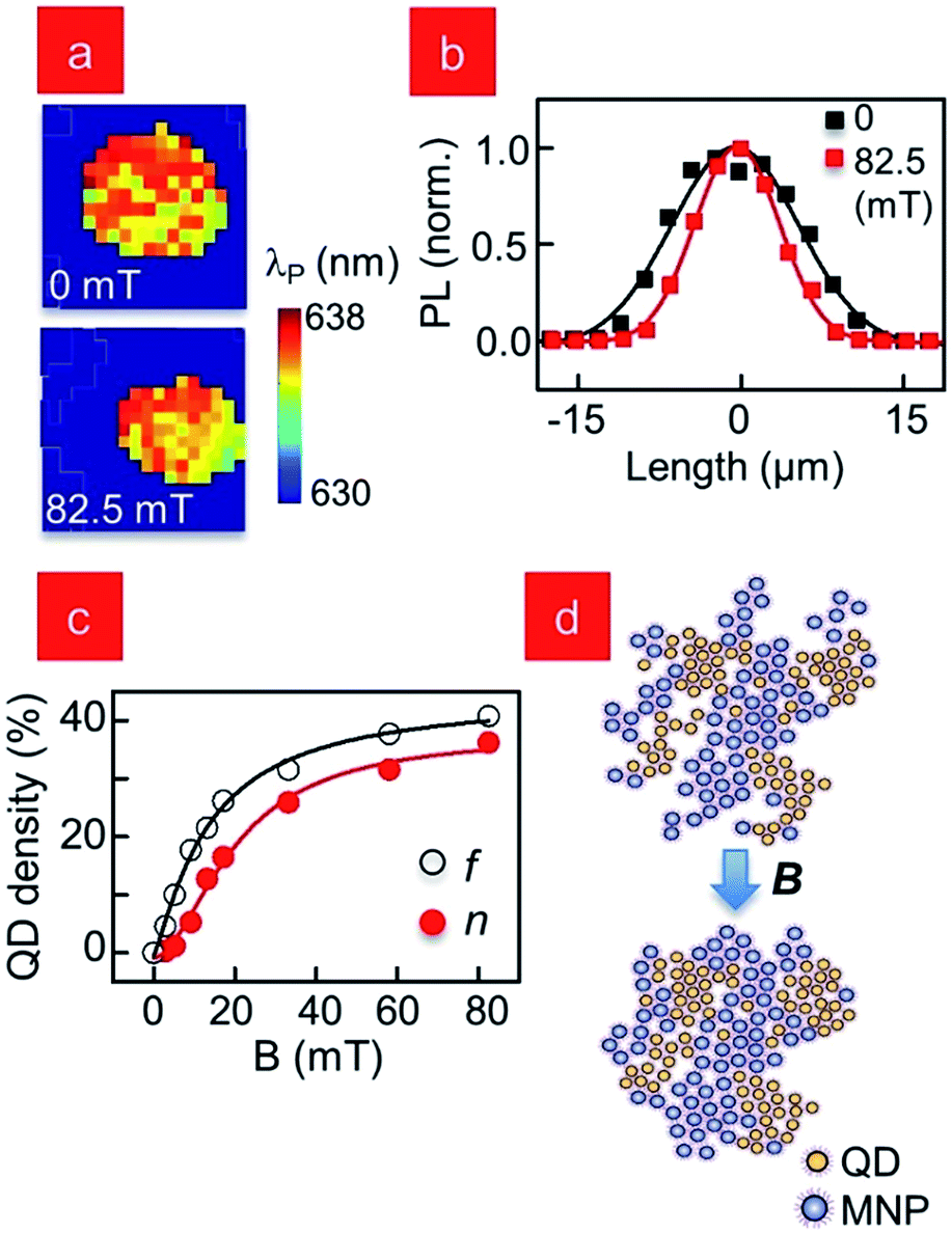 | ||
| Fig. 5 (a) Spatially-resolved map of peak wavelength λP for the cluster in Fig. 4a (b) profiles of the PL intensity of cluster in (b) for 0 (black) and 82.5 mT (red) (c) QD density increase estimated from PL intensity, f and spatial compaction measurements, n (d) schematic showing the compaction of the MNP–QD clusters with magnetic field. | ||
We schematically depict one possible mechanism in Fig. 5d. Prior to the application of B the internal structure of the cluster is an irregular and inter-connected network of aggregates with constant inter-particle spacing as typically seen for diffusion limited particle aggregation. Inter-particle separation is defined by partial interdigitation of surface ligands and the interstitial regions are occupied by the LC molecules. Initial LC orientation in and around the cluster should be approximately radial with local disorder, and this is detected in the θK map in Fig. 3b. The locally induced magnetic fields from the collective dipole moments of the MNPs within the cluster could cause the surrounding LC molecules and those inside the interstitial spaces to locally align along the externally applied B. In a feedback-like process this alignment induces compaction of the aggregates accompanied by expulsion of the voids, thus minimizing elastic deformation to the locally more aligned LC medium. The removal of the external B and subsequent thermal relaxation of the system, could then result in the LC molecules slowly returning to their original orientations, thus the clusters are released from their tighter packing arrangement and can open back out. This mechanism suggests that the LC-filled voids are an equilibrium feature at B = 0, whereas the less-packed cluster arrangement at B = 0 would seem to be a kinetically trapped arrangement. Another possible mechanism is in the “chaining” of the MNPs, aligned by B. Even in the case of superparamagnetic particles, the induced magnetic moments at very low fields could result in their lateral repulsion, and would likely induce their chaining along the field, as is the case in any magnetic fluid. This local ordering of the MNPs might result in a resultant brighter emission and also result in cluster compaction, as we have observed.
Conclusions
This spatial re-alignment and re-organization of the LC molecules in and around the clusters that leads to QD PL enhancement is a result of the cooperative behavior between the QDs, the MNPs and the LC material they are suspended in. We have suggested possible mechanisms that may be responsible for this observation, but at this juncture, we have to leave the final conclusion as an intriguing puzzle to the community. However, irrespective of the lack of absolute clarity regarding the driving process, given the very low external field required to produce the brightening we observe, and that the intensity change follows a well-defined function of the applied field and can be used to calibrate it, these clusters could be used as low magnetic field optical sensors. Our results demonstrate a truly synergistic, reversible, and an all-optical process to detect magnetic fields that is completely non-invasive and low loss, bypassing any need for electrical connections. As the nanoparticle clusters are self-assembled in a fluid medium and remain suspended in it, with future modifications, it would be possible for our sensors to be used in broad ranging fluid-based applications.Sample preparation
Nematic liquid crystal 4′-pentyl-4-biphenylcarbonitrile (5CB, Sigma Aldrich) is mixed with 2 mg ml−1 octadecylamine coated CdSe/ZnS core–shell QDs (NN Labs) and 5 mg ml−1 oleic acid coated iron-oxide MNPs (NN Labs) in toluene to a concentration of 0.02 to 0.05 wt% at QD:MNP ratios ranging between 2:1–1:10. The QD–MNP–LC mixture is bath sonicated at 50 °C so that the LC is in the isotropic phase for 6–18 hours to obtain even NP dispersion, verified by optical microscopy. For optical imaging, clean glass slides are dip coated with aqueous hexadecyltrimethylammonium bromide (CTAB) solution (5 μM) for one hour and dried under nitrogen to produce a homeotropic LC alignment layer. For a planar LC alignment layer, glass slides are spin-coated with aqueous polyvinyl alcohol (PVA) (1% by wt) and dried under nitrogen and then rubbed with a velvet cloth with uniform strokes. Samples are sealed with a similarly coated glass cover slip. To form the clusters, samples are cooled below the LC clearing temperature at 0.1 °C min−1 using a Linkham LTS350 hot-stage. The final samples are between 5–10 μm in thickness.
Spectroscopy and imaging
For QD PL measurements, a 532 nm continuous wave (cw) excitation laser is focused on the sample through a 100× Nikon objective to produce a diffraction-limited spot diameter of approximately 600 nm. Samples are mounted on a motorized high-resolution scanning stage, and spectra recorded with an Acton 300i Spectrometer which disperses the signal onto a thermo-electrically cooled CCD camera. For MNP imaging, magneto-optical Kerr effect (MOKE) measurements are taken with a cw He–Ne laser (632 nm). A photo-elastic modulator is used to modulate the signal at 50 kHz, and the Kerr rotation resolved using a standard lock-in amplifier technique with a resolution of 0.2 μrad.27 High-resolution PL spectroscopy and MOKE measurements are performed in the same setup with two collection paths, which allows simultaneous fluorescence and magnetic imaging of the NP co-assemblies.Small angle X-ray scattering (SAXS)
Measurements were carried out on Beamline 4-2 at Stanford Synchrotron Radiation Lightsource. Samples are prepared as for microscopy, and dispensed into 1.5 mm quartz X-ray capillaries for unaligned (powder) small angle scattering and exposed to an 11 KeV X-ray beam for 0.5 s in a custom-built mount with variable magnetic field. Diffraction patterns are recorded on a CCD detector, then plotted as integrated intensity as a function of q, the scattering vector using analysis software available at the beamline.Acknowledgements
This work was supported by funds from NSF DMR-1056860, and in part by the nanoBIO node of the National Science Foundation (ECC-1227034), the Material Research Laboratory (University of Illinois at Urbana-Champaign), and Professor Cathy Murphy's Laboratory (University of Illinois at Urbana-Champaign). We would also like to thank Prof. Ajay Gopinathan for helping us with the cluster compaction quantitative estimates.Notes and references
- Y. Sun, M. B. Salamon, K. Garnier and R. S. Averback, Phys. Rev. Lett., 2003, 91, 167206 CrossRef.
- M. De, P. S. Ghosh and V. M. Rotello, Adv. Mater., 2008, 20, 4225 CrossRef CAS.
- A. J. Nozik, M. C. Beard, J. M. Luther, M. Law, R. J. Ellingson and J. C. Johnson, Chem. Rev., 2010, 110, 6873 CrossRef CAS PubMed.
- S. A. Claridge, J. A. W. Castleman, S. N. Khanna, C. B. Murray, A. Sen and P. S. Weiss, ACS Nano, 2009, 3, 244 CrossRef CAS PubMed.
- M. Okuda, J.-C. Eloi, S. E. W. Jones, A. Sarua, R. M. Richardson and W. Schwarzacher, Nanotechnology, 2012, 23, 415601 CrossRef PubMed.
- Y. Zhang, S.-N. Wang, S. Ma, J.-J. Guan, D. Li, X.-D. Zhang and Z.-D. Zhang, J. Biomed. Mater. Res., Part A, 2008, 85A:3, 840 CrossRef PubMed.
- H. Kim, M. Achermann, L. P. Balet, J. A. Hollingsworth and V. I. Klimov, J. Am. Chem. Soc., 2005, 127, 544 CrossRef CAS PubMed.
- C. D. Cruz, O. Sandre and V. Cabuil, J. Phys. Chem. B, 2005, 109, 14292 CrossRef PubMed.
- B. M. Ross, L. Y. Wu and L. P. Lee, Nano Lett., 2011, 11, 2590 CrossRef CAS PubMed.
- V. Roullier, F. Grasset, F. Boulmedais, F. Artzner, O. Cador and V. Marchi-Artzner, Chem. Mater., 2008, 20, 6657 CrossRef CAS.
- A. Demortie`re, S. Buathong, B. P. Pichon, P. Panissod, D. Guillon, S. Beégin-Colin and B. Donnio, Small, 2010, 6, 1341 CrossRef PubMed.
- A. L. Rodarte, R. J. Pandolfi, S. Ghosh and L. S. Hirst, J. Mater. Chem. C, 2013, 1, 5527 RSC.
- A. Mertelj, D. Lisjak, M. Drofenik and M. Copic, Nature, 2013, 504, 237 CrossRef CAS PubMed.
- D. F. Gardner, J. S. Evans and I. I. Smalyukh, Mol. Cryst. Liq. Cryst., 2011, 545, 1227 Search PubMed.
- T. Dietl, Nat. Mater., 2010, 9, 965 CrossRef CAS PubMed.
- J. J. Vallooran, R. Negrini and R. Mezzenga, Langmuir, 2010, 29, 999 CrossRef PubMed.
- V. Salgueiriño-Maceira, M. A. Correa-Duarte, M. Spasova, L. M. Liz-Marzán and M. Farle, Adv. Funct. Mater., 2006, 16, 509 CrossRef.
- N. Insin, J. B. Tracy, H. Lee, J. P. Zimmer, R. M. Westervelt and M. Bawendi, ACS Nano, 2008, 2, 197 CrossRef CAS PubMed.
- S. P. Foy, R. L. Manthe, S. T. Foy, S. Dimitrijevic, N. Krishnamurthy and V. Labhasetwar, ACS Nano, 2010, 4, 5217 CrossRef CAS PubMed.
- J. Berezovsky, M. H. Mikkelsen, N. G. Stoltz, L. A. Coldren and D. D. Awschalom, Science, 2008, 320, 349 CrossRef CAS PubMed.
- F. Brochard and P. G. d. Gennes, J. Phys., 1970, 31, 691 CAS.
- S. V. Burylov and Y. L. Raikher, J. Magn. Magn. Mater., 1993, 122, 62 CrossRef CAS.
- K. I. Morozov, Phys. Rev. E: Stat., Nonlinear, Soft Matter Phys., 2002, 660, 11704 CrossRef.
- V. Berejnov, J.-C. Bacri, V. Cabuil, R. Perzynski and Y. Raikher, Europhys. Lett., 1998, 41, 507 CrossRef CAS.
- M. Goryca, P. Plochocka, T. Kazimierczuk, P. Wojnar, G. Karczewski, J. A. Gaj, M. Potemski and P. Kossacki, Phys. Rev. B: Condens. Matter Mater. Phys., 2010, 82, 165323 CrossRef.
- J. E. Tengood, I. S. Alferiev, K. Zhang, I. Fishbein, R. J. Levy and M. Chorny, Proc. Natl. Acad. Sci. U. S. A., 2014, 111, 4245 CrossRef CAS PubMed.
- K. Sato, Jpn. J. Appl. Phys., 1981, 20, 2403 CrossRef CAS.
| This journal is © The Royal Society of Chemistry 2015 |