 Open Access Article
 This Open Access Article is licensed under a
 Creative Commons Attribution 3.0 Unported Licence
Magnetically induced structural anisotropy in binary colloidal gels and its effect on diffusion and pressure driven permeability†
Christoffer
Abrahamsson
*ab,
Lars
Nordstierna
a,
Johan
Bergenholtz
c,
Annika
Altskär
d and
Magnus
Nydén
e
aDepartment of Chemical and Biological Engineering, Chalmers University of Technology, Kemivägen 10, 412 96, Gothenburg, Sweden. E-mail: abrahamc@chalmers.se
bSuMo Biomaterials, VINN Excellence Centre, Chalmers University of Technology, Gothenburg, 412 96, Sweden
cDepartment of Chemistry and Molecular Biology, University of Gothenburg, Kemivägen 10, 412 96, Gothenburg, Sweden
dStructure and Material Design, SIK – The Swedish Institute for Food and Biotechnology, SIK, PO Box 5401, 402 29 Gothenburg, Sweden
eIan Wark Research Institute, University of South Australia, Mawson Lakes Campus, Mawson Lakes, SA 5095, Australia
First published on 27th March 2014
Abstract
We report on the synthesis, microstructure and mass transport properties of a colloidal hydrogel self-assembled from a mixture of colloidal silica and nontronite clay plates at different particle concentrations. The gel-structure had uniaxial long-range anisotropy caused by alignment of the clay particles in a strong external magnetic field. After gelation the colloidal silica covered the clay particle network, fixing the orientation of the clay plates. Comparing gels with a clay concentration between 0 and 0.7 vol%, the magnetically oriented gels had a maximum water permeability and self-diffusion coefficient at 0.3 and 0.7 vol% clay, respectively. Hence the specific clay concentration resulting in the highest liquid flux was pressure dependent. This study gives new insight into the effect of anisotropy, particle concentration and bound water on mass transport properties in nano/microporous materials. Such findings merit consideration when designing porous composite materials for use in for example fuel cell, chromatography and membrane technology.
Introduction
A group of self-assembling nanostructures that has received much attention are the dispersions of binary combinations of colloidal spheres, rods or plates.1–3 Equilibrium phases of these mixtures often have rich phase behavior, displaying liquid crystal phases such as nematic or smectic. Onsager explained that isotropic phases of anisotropic colloids have a phase transition from isotropic to nematic at increased volume fractions of particles, resulting in particles having a higher degree of parallel alignment relative to each other.4 Orientational entropy decreases by the transition, but entropy is compensated by the gain of excluded volume interactions. Normally the phase behavior of colloidal plates is richer than spheres because of the extra orientational degree of freedom. By combining differently shaped colloids the addition of mixing entropy gives increasingly intricate phase behavior.5,6Nontronite clay is a naturally occurring aluminosilicate mineral that consists of 0.7 nm thick and typically 25–1000 nm wide crystalline plates that are built up of two tetrahedral layers of silica sandwiching an octahedral layer that hosts different ions (Al3+, Mg2+ and Fe3+). Being rich in Fe(III) ions, clays dispersed in liquids are able to align in moderate magnetic fields (around 1 Tesla)7–10 or electric fields.11,12 Clay plates in liquid dispersions are typically stacked face-to-face in larger aggregates, but can under certain conditions be dispersed into individual plates, forming exfoliated dispersions.7 Michot and co-workers found that equilibrium phases made up of exfoliated nontronite clay with a concentration below 0.6 vol% were isotropic and biphasic between 0.6 and 0.8 vol%. The phase separation took several months, resulting in an isotropic upper phase and a birefringent lower phase. Increasing the clay concentration further makes the two phase system evolve into a one-phase system by growth of the birefringent phase into a fully nematic state at 0.8 vol% and a nematic gel at ≥0.83 vol%. If enough salt is added to any of these phases a gel is formed or flocculation occurs, depending on the particle volume fraction and salt concentration.8 The samples are defined here as gels when they are in dynamic arrest which was determined by rheological methods described later in the paper.
Amorphous colloidal silica (SiO2) spheres form sols that can be destabilized by salts such as NH4HCO3, in which case stable gels have been shown to form at a salt level of 0.29 M for a 4.5 vol% silica sol.13
Within the geosciences, fluid permeability driven by pressure gradients have been studied in numerous systems of purified clays and clay soils.14–16 From these investigations it is clear that the salt concentration has a large impact on the structure and thereby the permeability of clay dispersions and gels. Generally, low salt concentrations result in clay gels adopting a “house of cards” structure, with the clay edges interacting with clay faces. At high salt concentrations clay face-to-face attraction causes stacking of clays, forming larger particles and in effect larger pores and higher permeability. Similarly, the presence of moderate salt levels has been theorized to reduce the interaction between water and the clay surfaces, effectively increasing the movement of water through the pores.15,16
Clay alignment, and in some cases its effect on mass transport properties has been the target of several studies in both pure clay dispersions and clay composites.17–21 Moreover, gas permeability in clay composites was studied by DeRocher and co-workers and they found that the permeability decreased noticeably when the clay particles were aligned perpendicular to the direction of the mass transport flux.22 Huang et al. compared the ion-conductivity, a property that has similarities to fluid permeability, between samples with aligned or non-aligned clays in polymer electrolytes at low clay concentration. They found that in the aligned material the conductivity was significantly increased in the direction parallel to the clay alignment.23,24
Colloidal systems with a combination of spherical and plate shaped particles are found in several everyday products and engineering applications, making their phase behavior and rheological properties of such systems a target for several studies.5,25,26 To the best of our knowledge, this is the first study of mass transport in binary colloidal gels with particles of different shapes.
This article is the first in a series of publications on the topic of mixed colloidal silica and nontronite clay gels. We start by examining the gelation and the gel microstructure and its effect on self-diffusion and the pressure driven flow rates (the latter from here on referred to as permeability), through a new type of aqueous binary sol–gel system consisting of colloidal silica spheres and nontronite clay plates. In particular we investigate how the self-diffusion and permeability depend on clay orientation and clay concentration.
Experimental section
Gel preparation and rheometry
In what follows, gels that formed in the presence and absence of a magnetic field, respectively, are referred to as magnetic and non-magnetic gels. Furthermore, gels that contain both colloidal silica and clay are referred to as mixed gels while gels with one component are referred to as pure silica gels or pure clay gels. Homogenous gelation from colloidal sols was achieved by in situ formation of the NH4HCO3 salt, through hydrolysis of urea (Sigma) by the enzyme urease (Sigma, Jack Bean-urease type IX, Specific activity ∼75![[thin space (1/6-em)]](https://www.rsc.org/images/entities/char_2009.gif) 000 U g−1).27 Sequential aggregation of clay first and subsequently of silica is expected as the latter aggregate around 0.3–0.4 M NH4HCO3, while the former is known to aggregate at between 10−5 and 10−2 M NaCl.7,13 The gradual build-up of salt concentration gave the clays time to align in the magnetic field before the clay particles aggregated and gelled. Colloidal silica increased the gel adherence to the sample glass tube walls and provided the aggregated clay network with extra mechanical support by adhering to the clay, in this way stabilizing the gels enough to withstand the gravitational pressure during the permeability experiments. A concentration of 4.1 vol% colloidal silica was selected as this is the minimum level of silica found to consistently achieve mechanically stable pure silica gels and at the same time has a relatively high permeability. Prior to each sample synthesis, an aqueous stock solution of the enzyme urease was prepared. Enzyme hydrolysis of 1 M urea was done at the reaction buffer pH of ∼9.2 and an enzyme concentration of 1.5 mg ml−1. Added amounts of urea were adjusted depending on the particle concentrations since these particles exclude salt ions from their volume. The salt production rate was monitored by conductivity over time, both with and without 4.1 vol% silica and was compared with a standard curve of known concentrations of NH4HCO3 with added ammonia to reach pH 9.2. Conductivity measurements showed that all urea had been hydrolyzed at the latest 7 days after the enzyme addition, resulting in 1 M NH4HCO3 concentration in the gels. Samples were prepared by mixing nontronite dispersion, silica sol, urea solution and MilliQ water (Millipore MilliQ, 18 MΩ cm) followed by the addition of the enzyme stock solution to initiate the gelation process. All samples were gelled at 25 °C with or without a NMR spectrometer of 11.7 Tesla magnetic field strength oriented along the length of the sample tube. The gelation was monitored over time through measurements of storage and loss moduli using a rotational rheometer (Paar Physica MCR 300), equipped with direct strain oscillation28 with a cone–plate geometry. Cone diameters of 50 (pure clay or mixed sol) and 75 mm (pure silica sol), both with a cone angle of 1°, were used. Frequency and strain were kept constant at 1 Hz and 0.01%, respectively. A standard solvent trap was used with a lid clad on the inside with a moistened cloth. The chamber was kept at 22 °C, as higher temperatures were found to cause disturbances due to water evaporation.
000 U g−1).27 Sequential aggregation of clay first and subsequently of silica is expected as the latter aggregate around 0.3–0.4 M NH4HCO3, while the former is known to aggregate at between 10−5 and 10−2 M NaCl.7,13 The gradual build-up of salt concentration gave the clays time to align in the magnetic field before the clay particles aggregated and gelled. Colloidal silica increased the gel adherence to the sample glass tube walls and provided the aggregated clay network with extra mechanical support by adhering to the clay, in this way stabilizing the gels enough to withstand the gravitational pressure during the permeability experiments. A concentration of 4.1 vol% colloidal silica was selected as this is the minimum level of silica found to consistently achieve mechanically stable pure silica gels and at the same time has a relatively high permeability. Prior to each sample synthesis, an aqueous stock solution of the enzyme urease was prepared. Enzyme hydrolysis of 1 M urea was done at the reaction buffer pH of ∼9.2 and an enzyme concentration of 1.5 mg ml−1. Added amounts of urea were adjusted depending on the particle concentrations since these particles exclude salt ions from their volume. The salt production rate was monitored by conductivity over time, both with and without 4.1 vol% silica and was compared with a standard curve of known concentrations of NH4HCO3 with added ammonia to reach pH 9.2. Conductivity measurements showed that all urea had been hydrolyzed at the latest 7 days after the enzyme addition, resulting in 1 M NH4HCO3 concentration in the gels. Samples were prepared by mixing nontronite dispersion, silica sol, urea solution and MilliQ water (Millipore MilliQ, 18 MΩ cm) followed by the addition of the enzyme stock solution to initiate the gelation process. All samples were gelled at 25 °C with or without a NMR spectrometer of 11.7 Tesla magnetic field strength oriented along the length of the sample tube. The gelation was monitored over time through measurements of storage and loss moduli using a rotational rheometer (Paar Physica MCR 300), equipped with direct strain oscillation28 with a cone–plate geometry. Cone diameters of 50 (pure clay or mixed sol) and 75 mm (pure silica sol), both with a cone angle of 1°, were used. Frequency and strain were kept constant at 1 Hz and 0.01%, respectively. A standard solvent trap was used with a lid clad on the inside with a moistened cloth. The chamber was kept at 22 °C, as higher temperatures were found to cause disturbances due to water evaporation.
Colloidal purification and characterization
The silica sol (Bindzil 40/130) with a pH of 9.10–9.20, consisting of a 18.2 vol% aqueous dispersion of silica spheres of density 2.2 g cm−3, was kindly provided by AkzoNobel Pulp and Performance Chemicals, Sweden. Before use, the sol was suction filtered with a Whatman 541 filter paper to remove any larger silica aggregates. Nontronite clay was purchased from Excalibur Mineral Corp., Peekskill, NY, from the source of Allentown, PA, having the following29 general formula [Na0.3Fe23+(Si, Al)4O10(OH)2·nH2O] and with an estimated unit cell density of 3 g cm−3. Clay dispersions were prepared by a modified standard protocol.7,8 In short, the clay was first ground, and subsequently dispersed in 1 M NaCl solution, followed by ultracentrifugation at 35000g, where the second step was repeated three times. Sample dialysis was done against deionized water until the conductivity remained constant, after which the dispersion was placed in Imhoff cones for 72 h to let mineral impurities sediment. Dispersions were size fractionated by centrifugation first at 6400g and then at 17000g. The clay fraction obtained after the last centrifugation was used in this study. X-ray diffraction and IR-spectroscopy were used to confirm mineral identity and purity. Transmission electron microscopy (JEOL 1200EX II microscope, JEOL, Tokyo, Japan) was used to visualize silica and nontronite particle appearance and nontronite size distribution at 120 kV. Imaging of particles was done by air-drying a drop of 0.01 vol% particle dispersion on a formvar and carbon-coated copper grid (Ted Pella Inc, Redding, CA, USA). Particle sizes were then measured in micrographs by the software ImageJ. The mean silica sphere diameter was found to be 22 nm with a standard deviation of 5 nm. All nontronite plates are assumed to have a thickness of 0.7 nm in accordance with the literature.7,8 The clay length and width were of comparable dimensions and followed a log–normal distribution pattern. Regression analysis of the log–normal distribution function on the histograms of experimentally determined clay dimensions resulted in a mean diameter, length and width of 228, 287 and 187 nm and standard deviations of 103, 161 and 93 nm, respectively. Each plates' diameter was defined as the (length + width)/2. Images of clays and their diameter size distribution, and the fitted log–normal function are shown in Fig. 1. Samples in NMR glass tubes (5 mm diameter) were photographed (Nikon D3200, Nikon Corp. with a Nikon AF-S 40 mm f/2.8 G objective) for birefringence between crossed polarizers one week after gelation.
 | ||
| Fig. 1 TEM micrographs of (A) exfoliated nontronite clay plates to the left and stacks of clays that are not fully exfoliated to the right and (B) histogram of nontronite plate size distribution with a fitted log–normal function (solid black line). | ||
Freeze drying and scanning electron microscopy
Gels were prepared in 1.5 ml Eppendorf tubes followed by freezing in liquid nitrogen, freeze drying, fracturing of the sample and sputtering with 10 nm of gold. Samples were imaged with a LEO Ultra 55 FEG scanning electron microscope (SEM) from Leo Electron Microscopy Ltd., Cambridge, England, operating at an acceleration voltage of 3 kV.Embedding and transmission electron microscopy
A detailed description for the sample preparation has been reported previously.30 In short, gel cubes of 1 mm edge length were cut from the inner parts of the samples, followed by exchange of the aqueous NH4HCO3 salt solution with salt solutions of increasing ethanol concentrations, ending with propylene oxide prior to infiltration in TLV resin (TAAB Low Viscosity Resin, TAAB Laboratories Equipment Ltd., England). Polymerization of resin took place at 60 °C and ultrathin sections ∼60 nm were cut with a diamond knife using an ultramicrotome (Powertome XL, RMC products, Boeckeler Instruments Inc, Tucson, AZ). The thin sections were placed on 400 mesh cupper grids and imaged using an accelerating voltage of 80 kV in a transmission electron microscope (TEM) of model LEO 906E made in LEO Electron Microscopy Ltd., Oberkochen, Germany. Distances between clay plates in embedded samples were measured in micrographs by the software ImageJ.NMR diffusion measurements
NMR experiments were carried out on a Bruker Avance 600 spectrometer (Bruker, Karlsruhe, Germany), equipped with a Diff30 diffusion probe with a maximum gradient strength of 1200 G cm−1 and with a 5 mm RF insert with 1H and 2H coils. Using the conventional stimulated echo sequence31 the gradient pulse length, δ, was set as short as possible (due to the presence of paramagnetic species): 0.3 ms. The gradient pulse was followed by a delay of 0.3 ms in order to suppress eddy currents. The longitudinal relaxation time was typically 150 ms which allowed for varying the diffusion time Δ = 10, 15, 20, 30, and 100 ms. In each experiment, the gradient strength g was linearly ramped in 32 steps and the maximum value was chosen to keep the variable kmax = (γgδ)2(Δ − δ/3) identical and independent of Δ for all experiments. All experiments were carried out at room temperature, with a sum of 8 acquisitions, and 2 s recycle delay time. The integral of the NMR signal was evaluated and normalized to the signal integral intensity of a standard 90°-experiment for each sample. The natural logarithm of the intensity was then plotted as a function of k. All measurements were performed within 2–3 weeks after sample gelation.The measurements were acquiring the diffusion coefficient along the same direction as the direction of the magnetic field during gelation. For all samples and experiments with varying diffusion times, a linear attenuation of the logarithmic intensity against k was noted at low k-values allowing for a simple fit to a one-component diffusion coefficient. The self-diffusion coefficient of water for each sample was given as the average value of the five experiments where Δ was varied. Non-linear attenuations were, however, noted at higher k-values but such details are outside the scope of this work.
Fluid permeability measurements
A simplified version of the “Falling head test” was used to measure permeability of the gels.32 The permeating liquid was a 1 M urea solution fully hydrolyzed by urease, from now on referred to as “salt solution”. To measure the permeability, each sample column was constructed by removing the bottom part of a 5 mm glass NMR tube, forming a glass tube to which a 210 micron polyester mesh was glued to one end as extra support for the gel. Parafilm was used to seal the meshed end, and the same end was filled with the sample sol up to 30 mm from the mesh. The other end was sealed with parafilm, and the sol was left to gel for 7 days. After removing the parafilm the column was fixed upright in a stand in a Petri dish with 8 mm deep salt solution and the column was filled with 90 mm of salt solution on top of the gel. The position of the top of the salt solution was recorded over time by marking the column with a marker pen 1–2 times a day for 21 days. Evaporation from the top of the column was minimized by sealing with parafilm that was slightly perforated to allow for constant atmospheric pressure. Tests confirmed that the evaporation from the top of the column was negligible within the timeframe of the experiment. Petri dishes were replenished by MilliQ water every day to compensate for water evaporation and all experiments were carried out at room temperature. The flow rate was deduced from the derivative of positions versus time, which was approximately linear for the first 7 days. Darcy's law was then used to calculate the permeability: | (1) |
In eqn (1), v (m s−1) is the flow speed of the liquid through the gel, κ (m2) is the permeability of the gel, μ (Pa s) is the dynamic viscosity of the salt solution, ΔP (Pa) is the pressure applied over the gel and Δz (m) the gel thickness. The gel synthesis and corresponding permeability measurements were repeated on two different occasions separated in time on one sample of each sample composition and on both occasions the permeability results were close to identical.
Results and discussion
Gelation, SEM and rheological characterization
Generally, a salt screens the charge of colloidal surfaces, reducing particle–particle repulsion, which may cause aggregation and gelation or flocculation.33 To achieve gelation, direct addition of all sodium chloride solution was attempted, but in the presence of clay this caused instant and inhomogeneous gelation with lumps of gel developing. To circumvent this an enzymatic route with in situ salt formation was utilized instead. Enzymatic salt generation has been explored in several colloidal systems, including colloidal silica.13,34 To the best of our knowledge, this is the first time it has been applied in gelation of mixed binary colloidal dispersions. Our gel synthesis also aimed to fix the orientation of the clays at the point of gelation after the gradual build up of the salt concentration, which allowed some time for magnetic alignment of the clays. In that context, rheology and visual observations of sample opacity was used to track the kinetics of the sol–gel transition. A “tilted tube test” was used to assess the gelation and it was found that all clay-containing samples formed transparent gels 10–20 minutes after adding the enzyme. Starting after ca. 1.5 hours, samples containing only silica became gradually more opaque as aggregates grew larger, resulting in a gel after ca. 2 h. Mixed samples with silica and clay showed a similar time dependence with regard to the appearance of sample opaqueness as the pure silica samples, independent of the clay concentration.Rheometry was used to get a more quantitative assessment of the gelation process. As shown in Fig. 2, the pure clay sample has a 30 times larger storage and loss modulus at the beginning of the experiment compared to the gelling pure silica dispersion or the mixed dispersion. Intuitively, the pure silica or mixed dispersion samples should display higher moduli due to the larger particle concentration compared with the pure clay sample. However, addition of colloidal spheres of silica to clay dispersions has been shown to reduce the modulus of clay dispersions. Kleshchanok and co-workers hypothesized that this was caused by silica binding to the clay edges,35 where the silica spheres provide both steric and electrostatic hindrance for the formation of a “house of cards” structure. As illustrated in Fig. 3, silica spheres prefer to bind to the edges of clays. In combination with our rheological results, it adds tentative support to the hypothesis of Kleshchanok et al.
 | ||
| Fig. 2 Development of storage (black lines) and loss (grey lines) moduli with time measured for the following colloidal dispersions/gels: 0.5 vol% pure clay (dashed lines), 4.1 vol% silica mixed with 0.5 vol% clay (dotted lines) and 4.1 vol% pure silica (solid lines). | ||
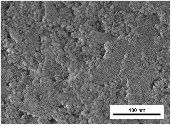 | ||
| Fig. 3 Scanning electron micrograph of the freeze dried and fractured mixed gel with 4.1 vol% silica and 0.5 vol% clay. The aggregated clay sheets are covered with silica particles that preferably bind to clay edges. | ||
Fig. 2 shows a rise in the moduli of the mixed particle dispersions starting at around 10 min, before leveling off after 2–3 hours. These observations are in agreement with visual observations of opacity, tilted tube test observations and rheometer measurements. In pure silica dispersions the increase starts after 2 hours and levels off after 3–4 hours.
Nontronite is known to gel at low ionic strength and as an example comparable nontronite dispersions with 0.5 vol% clay gelled below 0.01 M NaCl.7,8 NH4HCO3 being a monovalent salt below its pKa value of 10.3, is expected to cause gelation at roughly the same salt concentration as NaCl.36 Indeed, based on conductivity measurements a salt concentration of 0.01 M is reached within a few minutes after enzyme addition, at which time gelation also took place. This explains the comparably high starting modulus in the pure clay gels as it takes ca. 2–3 minutes before the first measurement can be performed due to the sample mounting procedure. Based on these observations it appears that the initial rheological response is dominated by clay–clay interactions. At the end of the rheometry measurements in Fig. 2 the mixed gel shows a slightly lower elastic modulus compared to pure clay gels, even though the particle concentration is higher. Comparable observations were made by Kleshchanok and co-workers and ten Brinke and colleagues on mixed systems with hectorite clay and colloidal silica.26,35
Rheometry measurements over longer time periods than presented in Fig. 2 were inaccurate, primarily due to water evaporation. The mechanical characteristics a week after gelation was therefore estimated simply by shaking gels in capped glass tubes. Based on such observations gels containing colloidal silica become substantially more mechanically robust than the pure clay gels. All samples containing colloidal silica proved to have enough mechanical strength and, importantly, enough adhesion to the column glass walls to withstand the pressure applied during permeability measurements that are described later in this paper. Pure clay gels on the other hand detached from the glass walls and collapsed during permeability measurements. This highlights the benefits of a supporting nanostructure, such as colloidal silica, when studying permeability through fragile low-density colloidal networks, such as clay gels.
Transmission electron microscopy
Fig. 4 reveals gel structures with finely dispersed colloidal networks of fractal-like appearance. Pure silica samples have a nanostructure consistent with previous reports, for instance by Iler.37 It should, however, be noted that the size of clay particles was not obtained from these images as the microtome section thickness is only 60 nm which effectively cuts the 200–300 nm sized clay particles into smaller entities. In the mixed gels the silica particles are typically associated with the clay surfaces, giving a distinctly different network structure compared to pure silica gels. Li and colleagues reported a similar network structure for mixed colloidal kaolinite clay and silica gels.38 Rheology, visually observed opacity and TEM results presented here support the mechanism proposed by Li et al. that the initial rise in moduli is caused mostly by clay–clay interactions while the later modulus increase is caused by silica network formation initiated at the clay surfaces.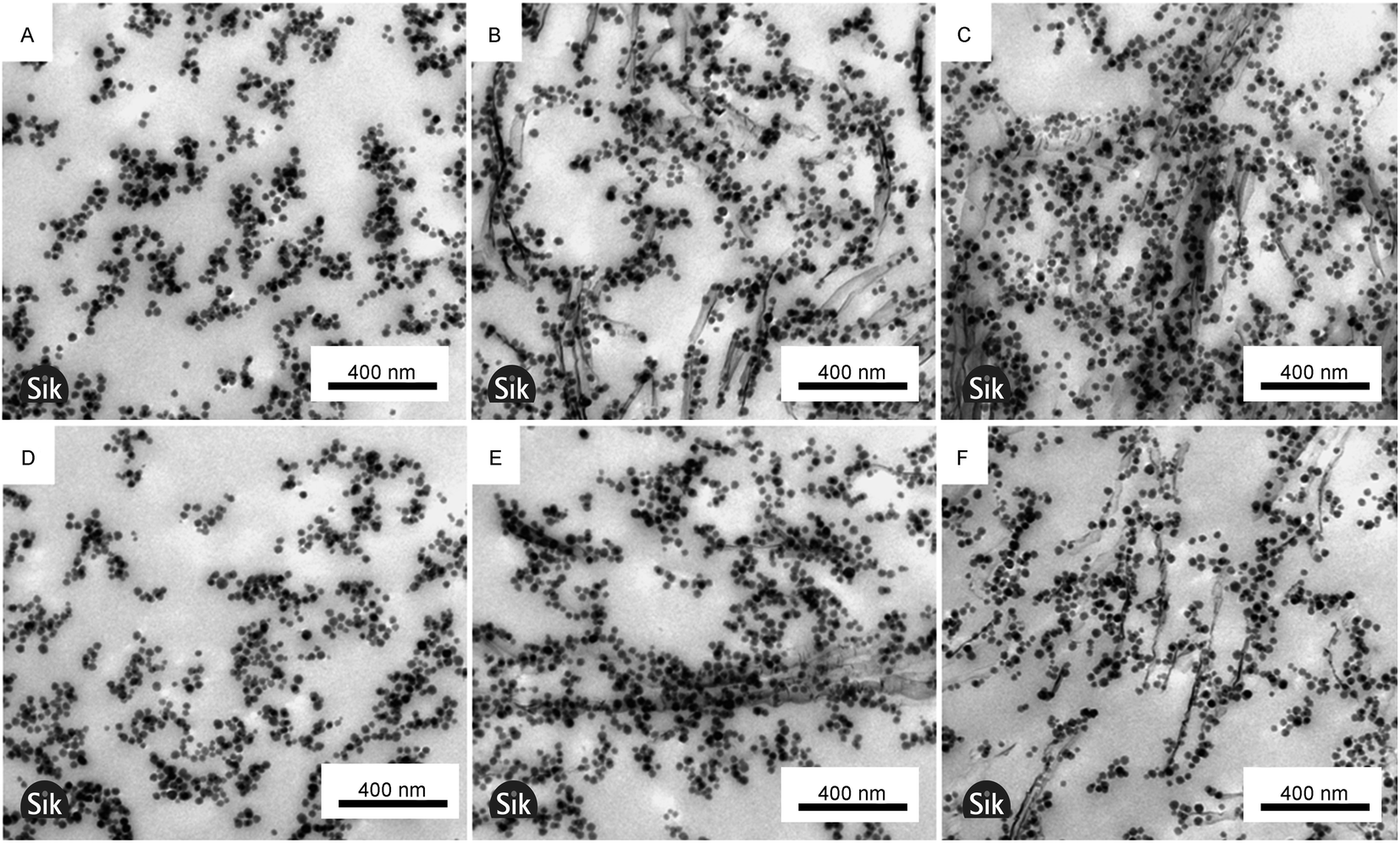 | ||
| Fig. 4 TEM micrographs of around 60 nm thick sections from resin embedded gels. The samples have the following content (A & D) 4.1 vol% silica, (B & E) 4.1 vol% silica with 0.3 vol% clay, and (C & F) 4.1 vol% silica with 0.7 vol% clay. A magnetic field was applied over the sample during gelation for samples A–C, but not for D–F. Note that the magnetic field direction at gelation is not known in micrographs. | ||
Mixed gels are more heterogeneous at a larger length scale than pure silica gels as illustrated in Fig. 4C and F, where Fig. 4C contains significantly more particles than Fig. 4F. To some extent the heterogeneity has its origin in aggregates of non-exfoliated clay plates, but the major cause of heterogeneity, as is exemplified by Fig. 4C and F, is local uneven spatial distribution of clay particles. As the silica particles associate with the clay surfaces the clay also determines the silica spatial distribution. Thus the relatively larger size of the clay compared to silica particles causes heterogeneity at a greater length scale in mixed gels compared to pure silica gels.
The TEM micrographs were used to estimate the distances between exfoliated adjacent clay plates and they were found to be 200 and 150 nm for 0.3 and 0.7 vol% clay, respectively, in the mixed gels. The corresponding standard deviations were 93 and 73 nm and the difference was therefore not statistically significant, indicating that the clays are more aggregated at a higher clay concentration. The values are significantly different from the clay spacing found in fully exfoliated pure nontronite dispersions found by Michot and colleagues. They found a spacing of 100 and 70 nm at 0.3 and 0.7 vol% clay, respectively.8 The high salt concentration and thereby increased clay aggregation in this work explain the difference. This conclusion is supported by birefringence observations and diffusion measurements discussed later. As exemplified by comparing Fig. 4A–C with Fig. 4D–F, the gelling of samples under the influence of magnetism has no noticeable effect on the local gel microstructure.
Optical observations and material anisotropy
Fig. 5 shows the effect of magnetic fields on the optical birefringence. The gels in Fig. 5A–L were gelled in the absence and presence of a magnetic field, respectively. In summary, gelation in a magnetic field always resulted in birefringence except for the pure silica gel that displays no birefringence in Fig. 5G. Given that the gels were imaged one week after preparation, the gelation maintains the magnetically induced anisotropy over time. Silica appears to reduce the birefringence in mixed gels as the pure clay gels in (F) and (L) are more birefringent than the mixed gels in (D) and (J). The effect is either due to less light passing through the gel caused by scattering or by a reduced clay alignment. Structural information from e.g. small-angle light scattering would be needed to make conclusive arguments. Interestingly the mixed gel with 0.7 vol% clay in Fig. 5E displays local regions of birefringence even though it gelled without applying a magnetic field, indicating local clay aggregation/alignment. This is further discussed below in the NMR diffusion section.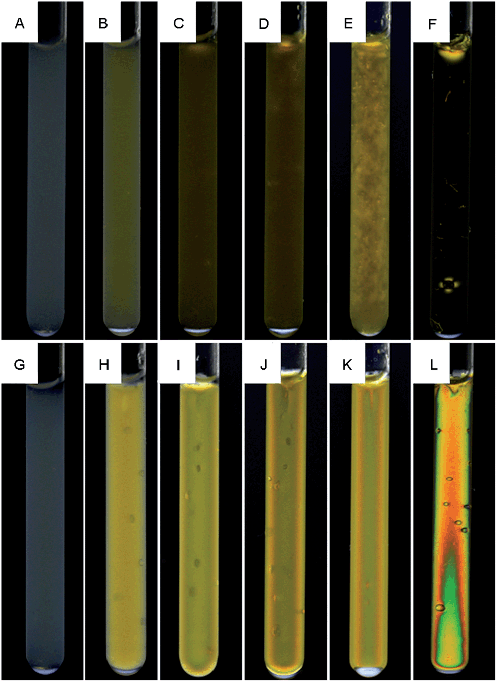 | ||
| Fig. 5 Birefringence in non-magnetic (A–F) and magnetic (G–L) gels for pure and mixed samples. Clay concentration from left to right in both rows: 0, 0.1, 0.3, 0.5, 0.7 and 0.5 vol%. (F) and (L) are pure clay gels, all other gels contain 4.1 vol% silica. The optical effect seen close to the bottom of the sample (F) is due to an air bubble. | ||
The long structural relaxation times of the gels are demonstrated in Fig. 5B–F. These non-magnetic gels gelled in the absence of a magnetic field and were a few weeks later exposed to a 14 T magnetic field for 6 hours after which they still displayed an isotropic optical behavior in both pure clay and mixed gels. This is in contrast with nontronite clay dispersions that orient readily even in moderate magnetic fields.8,10 A study of how the magnetic field strength and salt affect the structural relaxation time in low and high concentration clay gels is outside the scope of this work but seems warranted.
Self-diffusion measurements
Fig. 6 shows the ratio (D/D0,salt) between the self-diffusion coefficient of water in the gels and the self-diffusion coefficient of water in salt solution only, at different clay concentrations. In the following section, these results are evaluated in terms of obstruction, water binding to particle surfaces, and particle aggregation. Particle obstruction and bound water reduce the diffusion coefficient from its value in the neat solvent,18 while particle aggregation can explain an increase of the diffusion coefficient.39 In addition, the orientation of the clay plates is an important factor determining the water diffusion.40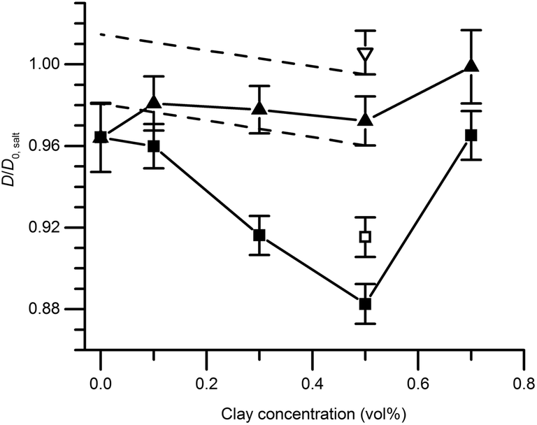 | ||
| Fig. 6 Relative self-diffusion of water measured with NMR spectroscopy in magnetic gels (triangles) or non-magnetic gels (squares). Gels are symbolized as follows: pure colloidal silica (4.1 vol%) and colloidal silica mixed with clay (filled symbols) and pure clay (open symbols). D0,salt is the self-diffusion in pure salt solution. The black dashed lines designate the limits of the decline in diffusion coefficient in the magnetic gels allowed for by the experimental error. Error bars depict the propagated standard deviation of the calculated diffusion coefficient described in the experimental section. | ||
The self-diffusion coefficients of water in the pure silica gels formed in the absence and presence of the magnetic field were identical, indicating that the gel formation was not affected by magnetic fields. This observation was also verified by the birefringence and TEM analyses. Diffusion obstruction in systems consisting of spherical particles that are at least one order of magnitude larger than the diffusant can be estimated by effective medium theory:39
 | (2) |
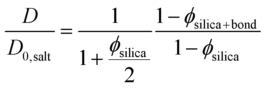 | (3) |
In eqn (3) the experimental D/D0,salt ratio was used to calculate the effective particle volume fraction ϕsilica+bound = 0.056. By subtracting the known volume fraction (ϕsilica) the thickness of the bound water layer was estimated to be 1.2 nm. This is in good agreement with what have previously been reported in the literature, indicating about 3 layers of bound water.42,43
Bharadwaj has presented a model that describes diffusion through composites with embedded thin plate shaped particles as a function of plate size, concentration, and orientation.40 With exchange between bound and free water taken into account (see eqn (3)), and by referring to the diffusion coefficient measured by NMR spectroscopy,44 the model can be rewritten as:
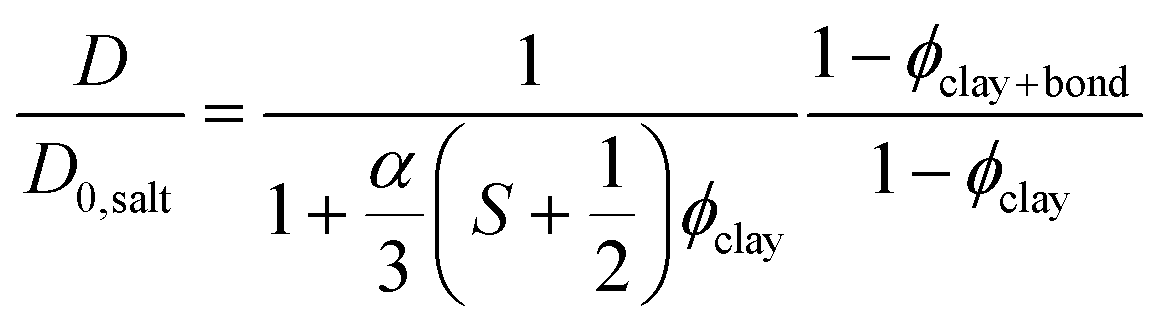 | (4) |
The experimentally determined self-diffusion coefficients of water are normalized to D0 and shown in Fig. 6. It is clear that the maximum diffusion coefficient difference (10%), for a magnetic relative to a non-magnetic mixed gel, appears at 0.5 vol% clay and not at the highest concentration 0.7 vol%. For this reason, the sample with 0.7 vol% is treated and analyzed separately at the end of this section.
There is no significant difference in water self-diffusion coefficient between 0 and 0.5 vol% clay in the magnetic gels with aligned clays. One interpretation is that there is no reduction in water mobility in the direction of the magnetic field. Tentatively, another explanation follows the maximum decline in diffusion coefficient allowed within the error bars as presented by the black dashed lines in Fig. 6. This decline yields, when used in eqn (4) with S = 0, a ϕclay+bound corresponding to a bound water layer thickness of 1.4 nm, which is in the same range previously reported for clay dispersions in the literature.42,45,46
The minor influence of bound water on the diffusion coefficient discussed in the previous paragraph, and the knowledge that the amount of bound and free water should be identical in the magnetic and non-magnetic gels, leads us to the following conclusion: the drastic reductions in diffusion at 0–0.5 vol% clay can only depend on the orientation of the clay plates. The ratio between the water self-diffusion coefficients in the magnetic and non-magnetic gels that contain clay as a function of clay volume fraction is described by the following equation:
 | (5) |
 | ||
| Fig. 7 The ratio Dmagnetic/Dnon-magneticversus clay concentration for pure silica and mixed gels (black squares) and pure clay gels (grey square). Error bars depict the propagated standard deviation of the calculated diffusion coefficient described in the experimental section. | ||
Excluding the 0.7 vol% sample, the trend strictly follows eqn (5) and a linear regression resulted in an aspect ratio α = 120 ± 4. An estimate of clay aggregation can be deduced by considering complete face-to-face packing of the aggregated clay plates. In this model, the clay diameter and thickness are 228 ± 8 nm (Fig. 1) and 0.7 nm respectively. Between the aggregated plates a 1.56 nm thick layer of non-exchangeable water is assumed.10,47 This results in 1.53 ± 0.9 plates in the average clay aggregate. Note that the number of plates in each aggregate is a characteristic of the whole clay gel network since the gels form one large aggregate. Comparing the pure clay and the mixed gel at 0.5 vol% clay, it is clear that silica has little influence on the number of clay plates in each aggregate, indicating that the presence of silica does not lead to depletion effects in these experiments, as this would have increased clay aggregation.3
Just as for the TEM and birefringence observations, the self-diffusion measurements point to increased aggregation in the mixed gels with 0.7 vol% clay compared to the other gels. Using eqn (5), the ratio between self-diffusion coefficients in the magnetic and non-aligned gels corresponded to 4.1 plates in each clay aggregate. Jointly these results indicate the 0.7 vol% clay samples already before the in situ formation of salt were birefringent gels that had with regions of comparably more closely spaced clays with local alignment.
Fluid permeability measurements
As seen in Fig. 8, the permeability is higher in magnetic gels compared to non-magnetic gels, with the exception of pure silica gels. The effect is attributed to the effect of clay alignment as discussed in the diffusion section above. Interestingly, permeability increased in mixed magnetic gels of low clay content compared to pure silica gels, even though the particle concentration is increased. Also, there is a permeability maximum at 0.3 vol% clay although the relative difference in permeability between magnetic and non-magnetic gels increases with clay concentration, reaching a factor of 2 at 0.7 vol%. | ||
| Fig. 8 Fluid permeability of the gel in column with salt solution on top (black curves), comparing permeability of magnetic gels (triangles) and non-magnetic gels (squares). The grey curve shows the relative percent increase in permeability for magnetic relative to non-magnetic gels. Gels are made of either pure colloid silica or silica mixed with varying amounts of clay. | ||
Fluid permeability bears similarities to ion conductivity, a material property that was studied in polymer composites with aligned or non-aligned clays by Huang and co-workers.23 Similarly to our liquid permeability results they found a maximum in the ion conductivity in aligned but not in non-aligned samples, when varying the clay concentration. The maximum was explained by an increased conductivity at low clay concentration caused by alignment of ion conducting channels formed in the clay/polymer interface. Furthermore, the ensuing decrease in ion conductivity was explained by increased clay aggregation at high clay concentration, resulting in fewer channels.
In analogy with the results of Huang and co-workers discussed above,23 we speculate that the increased permeability at low clay concentration observed in the mixed magnetic gels relative to the pure silica gels is caused by two mechanisms. Firstly channels of lower mass transport resistance are formed when clays are added to gels, and secondly these channels are aligned in magnetic fields. Fig. 4 illustrates that the channels form around the clays as the clay plates deplete the surrounding region of silica particles by adsorption. In the non-magnetic gels a similar but weaker effect is observed in the absence of clay alignment as the permeability remains unchanged even though the clay particle content is increased up to 0.3 vol%.
Above this concentration we propose that the increased clay concentration decreases the permeability due to the following. Adding more than 0.3 vol% clay does not result in further channel formation through the silica network as all silica already are associated with the clays. Instead an increasing clay concentration reduced the permeability by providing surfaces that bind water and thereby makes the effective volume available for flow smaller. The ratios between the clay plate and colloidal silica sphere total surface area in the mixed gels are estimated to be 0.26, 0.77 and 1.80 at 0.1, 0.3 and 0.7 vol% clay contents, respectively. This estimation assumed monodisperse particle size distributions equivalent to the measured average particle diameters with perfectly exfoliated round clay plates and silica spheres. Indeed the diffusion results discussed previously indicate that a substantial amount of water is associated with the colloidal surfaces.
TEM and birefringence results suggest that the clay particles are more heterogeneously distributed at higher clay concentrations. This also resulted in a larger water self-diffusion coefficient at 0.7 compared to 0.5 vol% clay content. However, the permeability is not affected in the same way as it decreases above a clay concentration of 0.3 vol% clay. The fact that the highest diffusivity in the mixed gels is observed at a clay content of 0.7 vol% and the largest permeability is observed at 0.3 vol% is notable. If we instead look for the largest relative difference in permeability, comparing magnetic and non-magnetic gels, it was found at 0.7 vol%. Similarly, a maximum water self-diffusion coefficient difference was found in the gels with 0.5 vol% clay. Hence the optimum clay concentration for either the maximum liquid flux or a maximum relative difference (fluxmagnetic/fluxnon-magnetic) in the flux through the gels, is pressure dependent for both diffusion and permeability. The results suggest that the mass transport observations have its origin in the colloidal phase behavior and the aggregation process prior to sample gelation. All in all these observations emphasize the benefits of measuring both diffusion and permeability when seeking to understand liquid mass transport in anisotropic microporous materials.
Few permeability studies have been made in colloidal gels15,48 and none of them have targeted the effect of gel network anisotropy or measured both diffusion and permeability of the solvent. Furthermore, differences in the mineral type, particle and salt concentration and general experimental design prevent us from making conclusive comparisons of our results with these studies.
Conclusion
In this study, we explored how the gel microstructure and water binding to surfaces affect water diffusion and permeability through gels made from colloidal silica and nontronite clay. Varying the clay concentration and comparing magnetic and non-magnetic gels, the specific clay concentration resulting in the highest liquid flux was pressure dependent as the largest relative difference in diffusion and permeability was found at 0.5 and 0.7 vol% clay, respectively. At this stage no detailed model has been constructed to fully explain the found microstructure/mass transport relationship and therefore the validity of our theories needs to be established by future mass transport simulations. Even so, the hydrogel system used in this study provides a well characterized model-material for investigation and understanding of liquid mass transport though microporous soft materials and the observations already made merit consideration when designing porous composite materials for use in for example fuel cell, chromatography and membrane technology. In particular this study highlights the benefits of exploring both diffusion and permeability to get a thorough understanding of the mass transport in the material. More studies of the microstructure in these gels are currently underway, aiming to further explain their intricate mass transport properties.Conflict of interest
The authors declare no competing financial interest.Acknowledgements
This work has been carried out with financial support from VINNOVA through the VINN Excellence Centre SuMo Biomaterials. The Swedish NMR Center is acknowledged for spectrometer time and Alexander Idström for his help with sample imaging. Jan-Erik Löfroth, Diana Bernin, Michael Persson, Kristin Sott and Tobias Gebäck are acknowledged for many valuable discussions.References
- M. Adams, Z. Dogic, S. L. Keller and S. Fraden, Nature, 1998, 393, 349–352 CrossRef CAS PubMed.
- H. N. W. Lekkerkerker and R. Tuinier, Colloids and the depletion interaction, Springer, 2011 Search PubMed.
- S. Oversteegen, C. Vonk, J. Wijnhoven and H. N. W. Lekkerkerker, Phys. Rev. E: Stat., Nonlinear, Soft Matter Phys., 2005, 71, 041406 CrossRef CAS.
- L. Onsager, Ann. N. Y. Acad. Sci., 1949, 51, 627–659 CrossRef CAS.
- D. de las Heras, N. Doshi, T. Cosgrove, J. Phipps, D. I. Gittins, J. S. van Duijneveldt and M. Schmidt, Sci. Rep., 2012, 2, 789 Search PubMed.
- H. N. W. Lekkerkerker and G. J. Vroege, Philos. Trans. R. Soc., A, 2013, 371, 20120263 CrossRef CAS PubMed.
- L. J. Michot, I. Bihannic, S. Maddi, C. Baravian, P. Levitz and P. Davidson, Langmuir, 2008, 24, 3127–3139 CrossRef CAS PubMed.
- L. J. Michot, I. Bihannic, S. Maddi, S. S. Funari, C. Baravian, P. Levitz and P. Davidson, Proc. Natl. Acad. Sci. U. S. A., 2006, 103, 16101–16104 CrossRef CAS PubMed.
- E. Paineau, K. Antonova, C. Baravian, I. Bihannic, P. Davidson, I. Dozov, M. Impéror-Clerc, P. Levitz, A. Madsen and F. Meneau, J. Phys. Chem. B, 2009, 113, 15858–15869 CrossRef CAS PubMed.
- P. Porion, A. M. Faugère, L. J. Michot, E. Paineau and A. Delville, J. Phys. Chem. C, 2011, 115, 14253–14263 CAS.
- E. Paineau, A. M. Philippe, K. Antonova, I. Bihannic, P. Davidson, I. Dozov, J. C. P. Gabriel, M. Impéror-Clerc, P. Levitz, F. Meneau and L. J. Michot, Liq. Cryst. Today, 2013, 1, 110–126 CrossRef CAS.
- R. Uhlhorn and O. Gaddy, Proc. IEEE, 1968, 56, 1140–1141 CrossRef.
- A. Schantz Zackrisson, A. Martinelli, A. Matic and J. Bergenholtz, J. Colloid Interface Sci., 2006, 301, 137–144 CrossRef CAS PubMed.
- R. P. Chapuis, Bull. Eng. Geol. Environ., 2012, 71, 401–434 CrossRef.
- G. Mesri, Clays Clay Miner., 1971, 19, 151–158 CAS.
- S. N. Rao and P. K. Mathew, Clays Clay Miner., 1995, 43, 433–437 CAS.
- E. De Azevedo, M. Engelsberg, J. Fossum and R. De Souza, Langmuir, 2007, 23, 5100–5105 CrossRef CAS PubMed.
- F. P. Duval, P. Porion and H. Van Damme, J. Phys. Chem. B, 1999, 103, 5730–5735 CrossRef CAS.
- D. M. Eitzman, R. Melkote and E. Cussler, AIChE J., 1996, 42, 2–9 CrossRef CAS.
- P. Porion, S. Rodts, M. Al-Mukhtar, A.-M. Faugère and A. Delville, Phys. Rev. Lett., 2001, 87, 208302 CrossRef CAS.
- C. Yang, W. Smyrl and E. Cussler, J. Membr. Sci., 2004, 231, 1–12 CrossRef CAS PubMed.
- J. P. DeRocher, B. T. Gettelfinger, J. Wang, E. E. Nuxoll and E. Cussler, J. Membr. Sci., 2005, 254, 21–30 CrossRef CAS PubMed.
- Y. Huang, M. Lee, M. Yang and C. Chen, Appl. Clay Sci., 2010, 49, 163–169 CrossRef CAS PubMed.
- S. Kitajima, M. Matsuda, M. Yamato and Y. Tominaga, Polym. J., 2012, 45, 738–743 CrossRef.
- J. C. Baird and J. Y. Walz, J. Colloid Interface Sci., 2006, 297, 161–169 CrossRef CAS PubMed.
- A. J. ten Brinke, L. Bailey, H. N. W. Lekkerkerker and G. C. Maitland, Soft Matter, 2007, 3, 1145–1162 RSC.
- Y. Qin and J. M. Cabral, Appl. Biochem. Biotechnol., 1994, 49, 217–240 CrossRef CAS.
- J. Läuger, K. Wollny and S. Huck, Rheol. Acta, 2002, 41, 356–361 CrossRef PubMed.
- E. Cloutis, Analytical data for mineral and rock samples, HOSERlab Mineral Database, accessed on: Jan 14 2014, http://psf.uwinnipeg.ca/Sample_Database_files/Mineral_database_latest.doc.
- M. Nordin, C. Abrahamsson, C. H. Blomqvist, H. Häbel, M. Röding, E. Olsson, M. Nydén and M. Rudemo, J. Microsc., 2014, 253, 166–170 CrossRef CAS PubMed.
- J. Tanner, J. Chem. Phys., 1970, 52, 2523 CrossRef CAS PubMed.
- F. Tavenas, P. Jean, P. Leblond and S. Leroueil, Can. Geotech. J., 1983, 20, 645–660 CrossRef.
- W. B. Russel, D. A. Saville and W. R. Schowalter, Colloidal dispersions, Cambridge Univ Press, 1989 Search PubMed.
- L. Gauckler, T. Graule and F. Baader, Mater. Chem. Phys., 1999, 61, 78–102 CrossRef CAS.
- D. Kleshchanok, V. Meester, C. E. Pompe, J. Hilhorst and H. N. W. Lekkerkerker, J. Phys. Chem. B, 2012, 116, 9532–9539 CrossRef CAS PubMed.
- D. D. Perrin, Ionisation constants of inorganic acids and bases in aqueous solution, Pergamon Press, NY, Oxford, Lond., Edinb., Paris, Frankfurt, 1982 Search PubMed.
- R. K. Iler, The chemistry of silica: solubility, polymerization, colloid and surface properties, and biochemistry, Wiley, New York, 1979 Search PubMed.
- W. Li, K. Lu and J. Y. Walz, J. Am. Ceram. Soc., 2011, 94, 1256–1264 CrossRef CAS.
- E. Cheever, F. D. Blum, K. R. Foster and R. A. Mackay, J. Colloid Interface Sci., 1985, 104, 121–129 CrossRef CAS.
- R. K. Bharadwaj, Macromolecules, 2001, 34, 9189–9192 CrossRef CAS.
- P. G. Nilsson and B. Lindman, J. Phys. Chem., 1983, 87, 4756–4761 CrossRef CAS.
- I. C. Bourg and G. Sposito, J. Colloid Interface Sci., 2011, 360, 701–715 CrossRef CAS PubMed.
- S. Kerisit and C. Liu, Environ. Sci. Technol., 2009, 43, 777–782 CrossRef CAS.
- F. Duval, P. Porion, A.-M. Faugère and H. Van Damme, J. Colloid Interface Sci., 2001, 242, 319–326 CrossRef CAS.
- C. T. Johnston, Clay Miner., 2010, 45, 245–279 CrossRef CAS PubMed.
- Y. Nakashima and F. Mitsumori, Appl. Clay Sci., 2005, 28, 209–221 CrossRef CAS PubMed.
- S. Karaborni, B. Smit, W. Heidug, J. Urai and E. Van Oort, Science, 1996, 271, 1102–1104 CAS.
- M. R. Noll, C. Bartlett and T. M. Dochat, Proc., Sixth National Outdoor Action Conf., 1992 Search PubMed.
Footnote |
| † Electronic supplementary information (ESI) available: A complete derivation of eqn (3) and details regarding the calculation of the adsorbed water layer thickness is available. See DOI: 10.1039/c4sm00315b |
| This journal is © The Royal Society of Chemistry 2014 |