Recent progress in Li-rich layered oxides as cathode materials for Li-ion batteries
Jianhua Yan
ab,
Xingbo Liu
b and
Bingyun Li
*a
aBiomaterials, Bioengineering & Nanotechnology Laboratory, Department of Orthopaedics, West Virginia University, 26506-9196, Morgantown, West Virginia, USA. E-mail: bili@hsc.wvu.edu; Web: http://medicine.hsc.wvu.edu/ortho-bli/ Fax: +1-304-293-7070; Tel: +1-304-293-1075
bDepartment of Mechanical and Aerospace Engineering, West Virginia University, Morgantown, West Virginia, USA 26506
First published on 11th November 2014
Abstract
The Li-ion battery represents one of the most important and most technically challenging components of electric vehicles. The cathode is one of the three key components (i.e., cathode, anode, and electrolyte) of the Li-ion battery and determines the battery quality. The demand for higher energy density, lower cost, and environmentally friendly batteries makes Li-rich layered oxides xLi2MnO3·(1 − x)LiMO2 (LR-NMC) among the most attractive candidates for future cathode materials. In this review, we discuss the state-of-the-art research activities related to LR-NMC materials, including their structures, mechanisms of high capacity and large voltage, challenges, and strategies that have been studied to improve their performances. Finally, we conclude with some personal perspectives for the future development of LR-NMC materials.
Introduction
The heavy carbonaceous emissions from vehicle engines and shortage of fossil fuels have attracted increased research interest in electric vehicles including plug-in hybrid electric vehicles (PHEVs), hybrid electric vehicles (HEVs), and electric vehicles (EVs).1 Battery-powered electric vehicles use an electric motor for propulsion with batteries for electricity storage. The energy in the batteries provides motive and auxiliary power onboard the vehicle. Electric vehicles offer the prospect of low air pollutants and relatively low cost of the electric motor, as well as very high efficiency. The main drawback is their reliance on batteries that presently have very low energy and power densities compared to oil fuels. In fact, HEVs are the only type which have been largely sold on the market in the past years, and Ni–metal-hydride (NiMH) batteries dominate the HEV industry. However, the NiMH batteries have low specific energy (1–2 kW h) and high cost that have limited their use in PHEV or EV applications.For PHEVs and EVs, Li-ion batteries (LIBs) seem to be promising2 and great progress has been made in developing their cathode materials, which are a key component of LIBs and determine the quality of LIBs. Among the LIB cathode materials studied, spinel oxides (LiM2O4), olivine phosphates (LiMPO4), and layered oxides (LiMO2) have attracted a significant amount of interest. LiMn2O4 is considered as a promising cathode material for LIBs due to its low cost, non-toxicity, and high thermal stability, and Ni-substitute LiNi0.5Mn1.5O4 has been found to have high power density with an active potential of 5 V.3 Olivine types of LiFePO4 and LiMnPO4 are of interest for use in large type LIBs due to their high intrinsic structural and chemical stability which have resulted in long cycle life batteries with low-cost and environmentally friendly properties.4 The layered LiMO2, in which M is a combination of Ni, Mn, and Co – so called NMC, is considered a potential next generation cathode material for LIBs since it has a moderate thermal stability and high rechargeable capacities (larger than 150 mA h g−1) at high rates.5
However, each kind of the above cathode materials has their limitations. The performance comparison for these materials is shown in Table 1. The battery system in the 40-mile PHEVs or EVs is expected to be designed with adequate cycle life and safety. Safety is a prerequisite for power LIBs and LIBs with high energy density must be able to sustain high operating temperatures and poor working conditions. Most of all, the battery systems should have sufficient energy capacity and adequate output peak power, both of which are often considered as two key criteria during material optimization and development. The demands of electric drive vehicles (EDV) for power LIBs are shown in Table 2.6
| Performance | LiCoO2 | NMC | LiMn2O4 | LiFePO4 |
|---|---|---|---|---|
| Cost/kW h | Higher | High | High | High |
| Safety | Poor | Poor | Average | Good |
| Cycle life | Average | Good | Average | Average |
| Power | Good | Good | Good | Average |
| Energy/W h kg−1 | Good | Good | Average | Poor |
| EDV type | Weight (max. kg) | Peak power (min. kW) | Power (min. W kg−1) | Capacity (min. kW h) | Energy (min. W h kg−1) |
|---|---|---|---|---|---|
| HEV | 50 | 40–60 | 800–1200 | 1.5–3 | 30–60 |
| PHEV | 120 | 50–65 | 400–540 | 6–12 | 50–75 |
| EV | 250 | 50–100 | 200–400 | 25–40 | 100–160 |
In the near-term, the above cathode materials, and a few other types, will be optimized and used in PHEVs and EVs. In the longer-term, new battery chemistries with significantly higher energy densities need to be developed to enable the development and use of PHEVs and EVs with a longer all-electric range. The United States Department of Energy is currently supporting exploratory research on LR-NMC cathode materials because of their high reversible capacities (>200 mA h g−1) and high operating voltages (∼4.8 V vs. Li/Li+). The energy density of LIBs is determined by the material's reversible capacity and operating voltage, which are determined by the material intrinsic chemistry. Therefore, understanding their intrinsic chemistry is very important. In this regard, we will focus on the intrinsic chemistry of this family of materials in this review.7,8
In this review, we will highlight LR-NMC materials with complex structures and mechanisms in detail, and will present their recent breakthroughs. Then, we will conclude with a summary of current and future research efforts and opportunities in the development of such cathode materials.
LR-NMC
A few years ago, Thackeray et al.9 proposed a new sophisticated strategy to increase the stability and improve the electrochemical characteristics of lithiated Ni–Mn–Co-oxides. Structurally compatible units like Li2MnO3 were used as partial substituents in lithiated transition metal oxides. Li2MnO3 is considered the best stabilized component for the Li[MnxNiyCoz]O2 electrode because it is electrochemically inactive over a wide potential window of 2.0–4.4 V and electrochemically active over 4.5 V.10–13 With excess Li ions introduced beyond the limitation of one Li ion per MO2 formula, exceptionally high reversible capacities and energy densities (>300 mA h g−1 and 900 W h kg−1) of these series of materials can be achieved when cycled between 2.0 and 4.8 V; besides, with the support of the stable structure of LiMn2O3, these materials have good capacity retention and thermal stability.14–17 There is a high probability that such materials with a higher capacity utilization and lower running costs could be further developed. In this regard, LR-NMC has been proposed as one of the most promising candidates.18,19 In the following section, we will highlight the progress and challenges of LR-NMC cathode materials.Structures
LR-NMC is represented by the general formula xLi2MnO3·(1 − x)LiMO2. Various design equations have been proposed to synthesize the materials, and high capacities can be obtained if x > 0.3.20–23 Park et al.22 designed a phase diagram consisting of LiNi1/2Mn1/2O2, LiCoO2, and Li2MnO3, as shown in Fig. 1a. The compositions located on the phase diagram can be expressed as Li[Cox(Li1/3Mn2/3)y(Ni1/2Mn1/2)1−x−y]O2. The Mn oxidation state of the solid solutions would be +4 in the triangular phase. The four samples shown in Fig. 1a were characterized by X-ray diffraction (XRD), as shown in Fig. 1b. All the patterns can be indexed to a single phase of the α-NaFeO2 type with space group R3m. The splitting peaks of 104 and 018 were considered as evidence for the degree of ordering layered structures.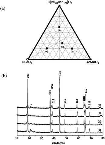 | ||
| Fig. 1 (a) A new triangle phase diagram of Li[Ni1/2Mn1/2]O2–LiCoO2–Li2MnO3 system. (b) XRD patterns for samples (a–d).22 Reprinted with permission from © 2005 Elsevier B.V. | ||
Structures made of these series of materials are hard to characterize and the reason for the complex structures may lie in the solid-solute phases formed by Li2MnO3 and LiMO2; both Li and transition metal ions coexist in the transition metal layer. There has been a significant amount of work on understanding the highly complex structures.24–34 First, Pan et al.24 analyzed Li[Li0.2Cr0.4Mn0.4]O2 using X-ray absorption spectroscopy (XAS) and nuclear magnetic resonance (NMR), and provided evidence for the formation of Cr- or Mn-rich regions; in other words, there are different metal clusters in different areas. Then, by calculating the lattice parameters existing in the superstructures, Lu et al.25 showed that the structural properties of these materials vary with composition. They believed that a solid solution was formed with an ordering of Li ions and transition metal ions in the transition metal layer due to the differences in the oxidation states. Lei et al.26 and Jarvis et al.27 supported Lu et al.'s findings by examining Li1.2Ni0.2Mn0.6O2 with XRD, high resolution transmission electron microscope (HRTEM), scanning transmission electron microscope (STEM), energy dispersive X-ray spectroscopy (EDS), and electron energy loss spectroscope (EELS). Li1.2Ni0.2Mn0.6O2 was found to be composed of a solid solution with C2/m monoclinic symmetry and an ordering of Li-ions and transition metal ions in the transition metal layer due to differences in the oxidation states. Thackeray et al.9 proposed a theory of a “composite” mixture with Li2MnO3-like and LiMO2-like domains which was formed by structurally integrating Li2MnO3 into LiMn0.5Ni0.5O2. As shown in Fig. 2a, these “composite” structures have domains with short-range order, rather than true solid solutions in which the cations are uniformly distributed within discrete layers. The Li2MnO3 component was activated to form a MnO2 component within a charged electrode structure, making these materials extremely versatile for tailoring and optimizing their composition, structure, and electrochemical properties. Yang et al. observed the two composites in Li1.2Ni0.15Co0.1Mn0.55O2 by in situ XRD as shown in Fig. 2b.32 The disappearance of the (020) reflection peaks upon charging to the voltage plateau above 4.5 V is indicative of the disappearance of Li/Mn ordering within the Li2MnO3 component, which indicates that the Li1.2Ni0.15Co0.1Mn0.55O2 material is a composite formed by conventional layered LiMO2 (M = Ni, Co, Mn) and Li2MnO3 components. Yu et al.33 illustrated the relationship between the electrochemical performance of this composite material and its composite components at room temperature. Kikkawa et al.34 further supported this theory by observing two independent Fe- and Mn-rich nanodomains in Li1.2Mn0.4Fe0.4O2 with STEM and EELS. They found that Li ions were first depleted from Fe-rich nanodomains and subsequently extracted from the whole region.
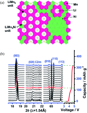 | ||
| Fig. 2 (a) Schematic structural illustrations corresponding to Li1+x(Mn0.5Ni0.5)1−xO2 (ref. 10) and (b) in situ XRD patterns collected during the first charge for Li1.2Ni0.15Co0.1Mn0.55O2 material.32 Reprinted with permission from © 2011 American Chemical Society10 and © 2013 WILEY-VCH Verlag GmbH & Co. KGaA, Weinheim.32 | ||
As yet, there are no definitive conclusions about the complex structures for this family of materials. However, the integrated composite theory seems to be well accepted. Due to the isostructure of Li2MnO3 and LiMO2, the composite forms and layers of Li+ ions alternate with layers containing a mixture of Li+, Mn4+, and M3+ ions in a cubic close-packed oxygen array. The presence of both Li+ and Mn4+ in the transition metal layer reduces the symmetry of Li2MnO3 from the R3m group to C2/m. Composites of two layered components of Li2MnO3 and LiMO2 are particularly attractive for designing electrodes in which Li is cycled in and out of the layered LiMO2 component while using the structurally compatible and, from a capacity standpoint, electrochemically inert Li2MnO3 component to provide stability to the electrode at a high voltage.28,33
Mechanisms of high voltage and large capacity
The capacity of the LR-NMC family of materials is commonly larger than 200 mA h g−1 with a high voltage plateau of ∼4.8 V. Many studies have been initiated in an attempt to determine the underlying mechanism(s) for the high capacity delivered by these materials.31,35–41 Two distinct regions are exhibited during the first charge as shown in Fig. 3.38 The initial sloping region A corresponds to the oxidation of the transition metal ions to M4+. In this stage, Li2MnO3 cannot be oxidized because of the high oxidation state of Mn4+. The plateau region B, ∼4.5 V, corresponds to a quick capacity increase due to the extraction of Li+ from Li2MnO3,39,40 which in turn leads to the formation of the MnO2 host structure in the compound which can then reversibly intercalate Li-ions. However, the initial discharge profile presents a large irreversible capacity. After the first cycle, this material still has a high capacity and capacity retention. Some researchers19,34,35,41 believe that a transformation from a layered structure to a spinel-like and layered mixed structure takes place after a deep delithiation–lithiation during the initial charge, and this transformation leads to the initial capacity fade. The transformed spinel-like nanodomain structure may offer excellent capacity retention as well as good rate capability in the subsequent long-term cycles. Additionally, other researchers found the initial capacity fade was also associated with Ni dissolution accompanied by an increase in oxidation states of remaining transition metals at surface regions of particles.28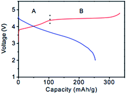 | ||
| Fig. 3 Schematic charge–discharge profiles of xLi2MnO3·(1 − x) LiMO2.38 Reprinted with permission from © 2007 Journal of Electrochemical Society. | ||
In general, two major mechanisms concerning the initial charge–discharge processes have been discussed. The first theory is the oxygen ejection mechanism proposed by Lu and his colleagues.19 They found that the capacity loss corresponded to the simultaneous removal of Li and O from the structure at the 4.5 V plateau. After the plateau, the cell could deliver stable reversible capacity between 2.0 and 4.6 V. Oxygen evolution was observed during the first charge process by in situ electrochemical mass spectroscopy measurements by Armstrong et al.42 The irreversible capacity loss was due to the extraction of Li as “Li2O” on charging beyond the oxidation of the transition metal ions above the 4+ state and the inability to insert all the Li-ions back into the lattice during discharge. The elimination of oxide ion vacancies at the end of the first charge led to a decrease in the number of Li-ion sites, resulting in a difference between the first charge and discharge capacity values. Additionally, after the initial charge, the transition metal moved into the Li layer to form a skeleton structure. Koyama et al.39 and Xiao et al.43 further supported this theory by calculating the oxygen stability with density functional theory (DFT + U) electronic structure calculations. Recently, Arunkumar and Wu44 identified factors that control the amount of oxygen loss and capacity fading. The amount of oxygen loss, which in turn influences the reversible capacity values in subsequent cycles, was determined by the amount of Li in the transition metal layer of the solid solution before charge. The tendency of Ni3+ to be reduced to Ni2+ and the consequent volatilization of Li during synthesis altered the Li content in the transition metal layer thereby influencing the degree of oxygen loss and reversible capacity values. A high Mn4+ content contributed to a decrease in oxygen mobility and loss during the initial charge.
A second major theory is the H+ exchange mechanism proposed by Robertson and Bruce.45 According to their work, the electrochemical activity of Li2MnO3 was found to involve the exchange of Li+ by H+ that leads to the formation of Li0.62H1.29MnO2.95. At discharge, Li0.62H1.29MnO2.95 goes back to Li1.28H0.66MnO2.97. Armstrong et al.46 supported this mechanism, and found a lot of H generation whose content corresponded to the amount of extracted Li+ ions at the plateau above 4.5 V. In addition, Johnson et al.47 and Li et al.48 found that some electrodes might deliver initial discharge capacities that exceed their theoretical values; proton exchange might have contributed to such an anomalous phenomenon.
In fact, both mechanisms may occur after electrochemical activation to 4.6 or 4.8 V. A typical schematic compositional phase diagram showing the electrochemical reaction pathways for xLi2MnO3·(1 − x)LiMO2 is shown in Fig. 4a.49 The initial charge process on a Li2MnO3–LiMO2–MO2 phase diagram of 0.3Li2MnO3–0.7LiMn1/3Ni1/3Co1/3O2 was used as the composition of a parent reference electrode. Li was initially extracted from the LiMO2 component of the electrode structure, typically at potentials <4.4 V vs. Li0, with concomitant oxidation of the transition metal ions to M4+. Thereafter, Li was extracted from the Li2MnO3 component (>4.4 V) accompanying irreversible loss of oxygen from the lattice as confirmed by in situ XRD25 and differential electrochemical mass spectrometry studies42 or from the proton exchange. At the same time, activation of the transition metal ions, such as Ni2+/Ni4+ and Co3+/Co4+, also increased and resulted in a high capacity.9,50,51 The Li extraction accompanying the oxygen loss facilitated the lowering of the oxidation states of the transition metal ions at the end of the first discharge thereby leading to a high reversible capacity in the subsequent charge–discharge cycles. If all the Li was to be removed from the electrode, Johnson et al.9,47 described that the two-step process during charge could be expressed by the following reactions:
| xLi2MnO3·(1 − x)LiMO2 → xLi2MnO3·(1 − x)MO2 + (1 − x)Li | (1) |
| xLi2MnO3·(1 − x)LiMO2 → xMnO2·(1 − x)MO2 + xLi2O | (2) |
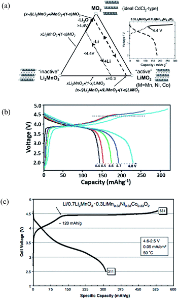 | ||
| Fig. 4 Electrochemical performance of xLi2MnO3–(1 − x)LiMn1/3Ni1/3Co1/3O2. (a) Li2MnO3–LiMO2–MO2 compositional phase diagram; (b) the charge–discharge curves for the 1st cycle of 0.3Li2MnO3–0.7LiMn1/3Ni1/3Co1/3O2; (c) initial charge–discharge profiles at 50 °C of a Li/0.7Li2MnO3–0.3LiMn0.33Ni0.33Co0.33O2 cell (0.05 mA cm−2).47,49,50 Reprinted with permission from © 2007 (ref. 49) and 2012,50 Royal Society of Chemistry. Reprinted with permission from © 2007 Elsevier Ltd.47 | ||
In addition to the Mn redox reactions, the charge compensation of oxygen may also contribute to high capacity. When increasing the potential in excess of 4.8 V, the charge–discharge cycling properties decrease. It is believed that changes in material structures have occurred due to the charge compensation of oxygen.9 Since it was effective to embed the inactive Li2MnO3 component within a LiMO2 structure to stabilize electrodes at high potentials, there are two strategies to generate high-energy batteries with the conventional layered cathode materials. There are changes that occur to the compositional, structural, and electrochemical properties of the electrodes and the importance of using a relatively high Mn content and a high charging potential (>4.4 V) to generate high capacity electrodes.10,47
The profiles of the initial charge–discharge cycles of a Li/0.3Li2MnO3–0.7LiMn1/3Ni1/3Co1/3O2 cell are presented in Fig. 4b.50 During the initial charge of the cell to approximately 4.4 V, Li was extracted from the LiMO2 component with a concomitant oxidation of the Ni and Co ions, while the Mn ions remained tetravalent until the Li2MnO3–MO2 tie-line was reached. During this reaction, depletion of Li ions from the Li layer was compensated for by the diffusion of Li from octahedral sites in the Mn layer of the Li2MnO3 component to tetrahedral sites in the Li-depleted layer thereby providing the additional binding energy necessary to maintain structural stability. Therefore, the Li2MnO3 component acted as a reservoir of surplus Li that could be used to stabilize the electrode structure at low Li loadings. If the electrochemical potential of the cell was raised above 4.4–4.8 V during charge, Li could be further extracted from the electrode as indicated by the solid line in the compositional phase diagram, and the capacity increased from 145 mA h g−1 to 235 mA h g−1. The initial charge capacity was therefore related to the voltage applied. Continuing to increase the voltage may further increase the initial discharge capacity. As shown in Fig. 4c,47 an anomalous discharge capacity of 311 mA h g−1, exceeding the theoretical values [242 mA h g−1, calculated from reactions (1) and (2)] for lithiation back to the rocksalt stoichiometry, has been observed for 0.7Li2MnO3–0.3LiMn0.33Ni0.33Co0.33O2. A possible explanation for the higher-than-expected capacity was possible side reactions involving electrolyte oxidation and proton exchange.47,51
Challenges
LR-NMC can provide high capacity and seem to be an attractive candidate for LIB applications. However, LR-NMC has two well-known limitations: a large irreversible initial capacity loss (40–100 mA h g−1) and poor rate performance. The irreversible capacity loss is associated with the elimination of oxide ion vacancies from the layered lattice at the end of the first charge, which will quickly react with carbonate-based solvent thus generating inactive by-products at high operating voltages (e.g., 4.8 V). The poor rate performance is associated with the insulating Li2MnO3 component and the thick solid/electrolyte interfacial (SEI) layer formed by a reaction of the cathode surface with electrolytes.A third concern with LR-NMC is its fast energy fade with cycling. There are three major contributors to energy fade: (i) impedance rise which may be because Li atoms occupy different oxide sites during charge and discharge for the same voltage and/or capacity. The pulse discharge–charge behavior, characterized by an empirical parameter called the area specific impedance (ASI), is influenced by electrode thickness. It serves as a quick and simple means to estimate the impedance of cells under given conditions. (ii) Voltage fade and hysteresis which arises from crystal structural transformation in the oxide. (iii) Capacity fade because of the difficulty for Li+ trapping in negative SEI film caused by the crystal structural changes during cycling. Among these three factors, voltage and capacity fade contributes ∼90% to the energy fade and this implies that there is still room for improvement with electrode/electrolyte optimization.52
The voltage fade and capacity fade are associated with internal phase transitions. Some preliminary results53–55 indicated that voltage fade was unaffected by coatings, additives, cation doping, and substitution, whereas, the cut-off voltage and cation ordering in the crystal structure substantially influenced voltage fade. First, the lower the cycling cut-off voltage, the less voltage fades. No voltage fades occur when an upper cut-off voltage of 4.3 V is used as cycling voltage. Secondly, improving Li mobility at the top charge and controlling cation disorder for all states of charge could mitigate voltage fade. In addition, Croy et al.56 presented that the voltage fade and hysteresis were both increasing with increasing Li2MnO3 content. However, the structural change during cycling was not clearly understood. On the other hand, although the initial cycle treatment is useful for capacity retention, the “activation” leads to irreversible structural changes, surface damage, voltage fade, and hysteresis. Voltage fade and capacity fade are critical for energy fade, thus the structural change and corresponding mechanisms must be further studied. For example, what are the possible structural changes of the electrode materials during the initial charge–discharge processes of the Li-extraction and upon prolonged cycling? How do the electrodes' performances correlate with structure, morphology, and thermal behavior of LR-NMC materials? In addition, the reaction mechanism, which may lead to structural changes, is also not clearly understood. Questions remain related to the abnormal phenomenon of excess capacity beyond the theoretical values57,58 and where oxygen goes during the initial charge and discharge. Although the two well-known mechanisms have been proposed and discussed above, there are still many concerns. For instance, in the oxygen evolution mechanism, where does the oxygen go after its removal from the cathode structure? If it goes to the electrolyte, it could threaten the safety of the battery. Hong et al.37 even argued that there was not any oxygen ejection from the structure and the oxygen formed a π bonding with transition metal at the 4.5 V plateau. In the H+ exchange mechanism, the H+ is generated in the electrolyte, but does this influence the stability of the cathode structures? Assuming both of these mechanisms about the initial cycle are correct, how about subsequent cycles? There is very little literature addressing these issues.
In addition, it is difficult to find other battery components (i.e., anode and electrolyte) that can match the wide-range of voltage of the LR-NMC class of materials to assemble a battery. To achieve a high capacity, generally the charge–discharge potentials applied to the cells are between 2.0 and 4.8 V. Different discharge cut-off potentials give different capacities as shown in Fig. 4b. To achieve optimal performance, the batteries generally operate below a specific working potential, above which the electrochemical performance suffers. Therefore, chemists must find suitable anode materials and novel electrolytes; electrolyte erosion at high voltage is a major concern. Also, chemists must control side effects such as poor cycle life, safety issues, and poor rate capability with the increasing voltage plateau. Recently, for example, Envia-System reported a layered-layered Li2MnO3·LiMO2 composite based battery with high energy density of 400 W h kg−1. This battery used nano Si–C composite as an anode material and a high-voltage new electrolyte with additives. However, there are some limitations. The high irreversible capacity loss is undesirable, oxygen loss leads to gassing in pouch cells, and fade in average voltage upon cycling and high Mn dissolution lead to poor cycle life and calendar life.7
Improvement strategies
To overcome performance degradation and to decrease the cost of LR-NMC materials, efforts, such as optimizing synthesis methods, surface modification, elemental doping, use of composites and nanosized materials, and others, have been investigated.Synthesis technology
While the search for high performance LR-NMC for LIBs remains a primary objective, cost associated with producing these materials is now becoming another overriding factor. Sustainability, renewability, and green chemistry concepts must be taken into consideration when selecting cathode materials and processing methods for LR-NMC based batteries, especially for high volume applications. Synthesizing technology has a great impact on atomic order and subsequently affects the crystallinity degree, micro morphology, and distribution of material components. The electrochemical properties were also found to depend on the cooling rate used during material synthesis.59,60 Thus, selecting suitable processing methods is of importance.The common processing methods for LR-NMC include coprecipitation,61,62 spray pyrolysis,63,64 simple solid-phase,65 combustion,66 molten salt,67 sol–gel,68,69 hydrothermal,70,71 ball-milling–annealing,72 carbon-thermal reduction,73 and others.74–76 Generally speaking, the hydrothermal process has the lowest cost and it can be easily tuned to obtain nanostructures using different solvents, co-solvents, or surfactants. The co-precipitation process depends on the precipitation and crystallization of the targeted compounds under normal temperature and pressure conditions. The secondary particles prepared by this method are spherical with uniform sizes, which ensure a more stable performance. For example, Li et al.62 synthesized a high-voltage layered Li[Li0.2Mn0.56Ni0.16Co0.08]O2 cathode material by the co-precipitation method. After the initial decay, no obvious capacity fading was observed when cycling the material at different rates. Steady-state reversible capacities of 220 mA h g−1 at 0.2 C, 190 mA h g−1 at 1 C, 155 mA h g−1 at 5 C, and 110 mA h g−1 at 20 C were achieved in long-term cycle tests within the voltage cut-off limits of 2.5 and 4.8 V at 20 C. The spray pyrolysis is a versatile process with regard to the powder synthesis of inorganic and metal materials. The advantages of spray pyrolysis are that control of particle size, particle size distribution, and morphology is possible. The electrochemical performance of 0.3Li2MnO3–0.7LiNi0.5Mn0.5O2 cycled between 2.0 and 4.8 V at room temperature and 30 mA g−1 is shown in Fig. 5.64 The initial charge capacity of the cell was 290 mA h g−1, in which 144 mA h g−1 was delivered by LiNi0.5Mn0.5O2 and 130 mA h g−1 by Li2MnO3. The high first-cycle irreversible capacity loss of the cell was typical of a double-layered composite electrode. However, in subsequent cycles, the coulombic efficiency remained at nearly 100% and the discharge capacity of the cell decreased from 215 mA h g−1 to 205 mA h g−1 by the 40th cycle with capacity retention of 95%.
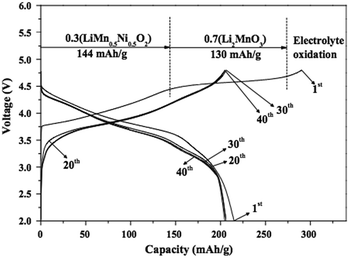 | ||
| Fig. 5 Cycling properties of the cathode powders with post-treated at 800 °C.64 Reprinted with permission from © 2012 Elsevier Ltd. | ||
Surface modification
Surface modification is an important method to improve the electrochemical performance by means of providing a protection layer to minimize the direct contact of the active material with electrolyte or modifying surface chemistry.77 LR-NMC materials have certain problems such as first-cycle irreversible capacity loss and inferior rate capability. What's more, structural and compositional stability under electrochemical cycling limits the useful capacity of the oxides for practical applications, because material degradation could result in declining performance and safety concerns. Any side reactions that consume or produce Li-ions change the capacity balance between anode and cathode. Such changes are irreversible and can be accumulated throughout the cycling processes, and may eventually lead to a significant capacity fade.78,79 Optimizing the surface region of layered oxide grains is of particular importance since the surface not only experiences Li insertion/extraction as the bulk, but also serves as the interface between cathode and electrolyte.Surface coating has proven to be effective in improving capacity retention, rate capability, and even thermal stability of LR-NMC materials. The main mechanisms for the positive effect of surface coatings on the performance of this family of materials include: (1) forming a physical protection barrier that reduces possible side reactions between cathode and electrolyte. The surface coatings may stabilize the surface and interface of the cathode active materials, decrease oxygen loss, and suppress phase transition. (2) Acting as a hydrogen fluoride (HF) scavenger to reduce the acidity of non-aqueous electrolyte and suppress Mn3+ dissolution from cathode. (3) Modifying cathode surface chemistry to improve rate capability.78
One possible way to extend cathode life and enhance rate capability of LR-NMC materials is to coat particle surfaces with carbon or metal oxides. A variety of materials such as C,80 ZrO2,81 TiO2,82 Al2O3,81,83 MgO,84,85 and Ni and Mn composite oxides86 have been used for surface coating and shown improved performance. For example, Zhao et al.85 prepared MnO-coated Li[Li0.2Ni0.2Mn0.6]O2 and obtained high reversible capacities of 211 and 210 mA h g−1 at high discharge rates of 1 C and 2 C, respectively, after 50 cycles. Myung et al.81 reported that Al2O3-coated Li[Li0.05Ni0.4Co0.15Mn0.4]O2 had good cyclic performance with a discharge capacity of 175 mA h g−1 under 30 mA g−1. In these materials, the coated metal oxide layer was transformed into a metal fluoride layer during cycling, as proved by secondary ion mass spectroscopy. The newly formed metal fluoride layer was quite effective against HF attack during cycling. AlF3 (ref. 87–90) was also widely studied as a coating layer due to its effectiveness against HF attack during cycling and high active energy to destroy Al–F bonds. Fig. 6a88 shows the initial charge and discharge curves of the uncoated and AlF3-coated Li(Li0.17Ni0.25Mn0.58)O2 with a cut-off potential of 2.0–4.8 V. The initial charge capacities of the uncoated and AlF3-coated samples had the same value of 275 mA h g−1, while the discharge capacities were 210 and 246 mA h g−1, respectively. The Coulombic efficiencies for the initial charge and discharge capacities of the uncoated and AlF3-coated samples were 76.4% and 89.5%, respectively. The polarization in the high potential region was lower for the AlF3-coated sample (inset in Fig. 6a), resulting in the effective Li extraction and subsequent Li insertion. Apparently, the decomposition of electrolytes at the end of the initial charge was greatly suppressed in the AlF3-coated samples. Fig. 6b compares the discharge capacities of the uncoated and AlF3-coated samples. Clearly, the AlF3-coated sample delivered a discharge capacity about 20% higher than the uncoated one. After 49 cycles, the discharge capacity of 232 mA h g−1 still remained for the AlF3-coated samples, indicating that the cyclic stability can be improved by AlF3 surface coatings.
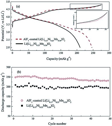 | ||
| Fig. 6 (a) The first charge–discharge curves and (b) cycle performance of the as-prepared and AlF3-coated Li(Li0.17Ni0.25Mn0.58)O2 at 0.2 C rate.88 Reprinted with permission from © 2012 Elsevier Ltd. | ||
Besides carbon and metal oxides and fluorides, a variety of hydroxides and inert phosphates with host structures for Li+ insertion/de-insertion such as AlPO4 and Co3(PO4)2,91,92 LiCoPO4,93 LiNiPO4,94 LiMnPO4,95 and Al(OH)96 have been used as coating materials and shown to be effective in improving initial capacity retention and rate capability. For example, Kang and Thackeray94 coated 0.5Li2MnO3·0.5LiNi0.44Co0.25Mn0.31O2 with LiNiPO4 and achieved an initial discharge capacity of 200 mA h g−1 under 1 C in comparison with ∼170 mA h g−1 without coating. Wang et al.92 fabricated double-coated layers: an inner layer of 2 wt% AlPO4 or 2 wt% CoPO4 and an outer layer of 2–3.5 wt% Al2O3 on Li[Li0.2Mn0.54Ni0.13Co0.13]O2. The capacity of their modified material was above 215 mA h g−1 at 2 C and, at low discharge rate, was up to 295 mA h g−1 with only 26 mA h g−1 capacity loss.
In addition to surface coating, changing surface chemistry is another effective way to improve structural and thermal stability and therefore performance of LR-NMC materials. For instance, some transition metal ions can enter the lattice matrix of cathode materials during annealing and stabilize the cathode structure. As a result, electrode resistance, side reactions, and heat generation during cycling can be reduced, and improved cycle life, rate capability, reversible capacity, coulomb efficiency, and overcharge tolerance can be obtained.77,97 Kim et al.98 reported that HNO3-treatment of 0.3Li2MnO3·0.7LiMn0.5Ni0.5O2 electrodes significantly improved the coulombic efficiency of the initial charge–discharge reaction but unfortunately decreased the initial discharge capacity from 259 to 205 mA h g−1. Denis et al.99 treated Li[Li0.2Mn0.54Ni0.13Co0.13]O2 cathode with (NH4)2SO4 solution and achieved a capacity of 230 mA h g−1 at 1.2 C discharge rate. The high capacity was attributed to the surface transformation from a layered structure into a spinel structure along with part of the Li ions de-insertion.34,41 Materials with spinel structures have three-dimensional diffusion channels for Li-ions which may lead to good rate performances. Abouimrane et al.100 treated Li1.12Mn0.55Ni0.145Co0.1O2 using a thermal reduction method, and obtained capacities of 231 and 196 mA h g−1, respectively, under 0.8 C and 1.6 C discharge rates. Zhang et al.101 prepared surface nitrided Li[Li0.17Ni0.25Mn0.58]O2 cathodes. The discharge capacity, high-rate capability, and cyclic stability of the nitrided samples improved dramatically in comparison with the untreated samples (Fig. 7). The high-rate discharge capabilities of the nitrided and untreated samples were investigated at different rates (0.1, 0.2, 0.5, 1, 3, and 5 C with 1 C = 300 mA g−1), as illustrated in Fig. 7a and b. The discharge capacities of the untreated sample were 126.7 mA h g−1 at 5 C, while for the nitrided sample, the discharge capacity at the 5 C rate was 164.7 mA h g−1. The improved high-rate capability of the nitrided sample was probably due to fast charge-transfer kinetics arising from the surface nitridation treatment. The cyclic properties for the nitride and untreated samples were shown in Fig. 7c and d. At a low current density of 0.1 C, the cyclic stability of the nitride sample was improved and, after 60 cycles, the discharge capacity of the nitrided samples was 256 mA h g−1, demonstrating a good capacity retention. By contrast, the discharge capacity of the untreated samples quickly decreased from 224 mA h g−1 to 141 mA h g−1 after 57 cycles. At a higher discharge rate of 1 C, the nitrided samples still showed a better performance than the untreated samples. Zheng et al.102 reported the effects of persulfate treatment on Li[Li0.2Mn0.54Ni0.13Co0.13]O2, and found that Na2S2O8 treatment greatly improved the first cycle efficiency of the active material to nearly 100%, and the rate performance was also increased to > 200 mA h g−1 at 1 C rate. The reason for the improved rate performance following Na2S2O8 treatment was probably attributed to the formation of the spinel phase on the material surface and the extraction of Li and oxygen, which may result in decreased electrochemical resistance.
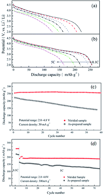 | ||
| Fig. 7 Rate capabilities of the (a) as-prepared and (b) nitrided Li[Li0.17Ni0.25Mn0.58]O2 at 0.1, 0.2, 0.5, 1, 3, and 5 C rates (1 C = 300 mA g−1). Cycle performances of the (c) as-prepared and (d) nitrided Li[Li0.17Ni0.25Mn0.58]O2 electrodes.101 Reprinted with permission from © 2012, Royal Society of Chemistry. | ||
In summary, surface modifications seem to be effective in improving the performance of LR-NMC materials. However, there are still some concerns. For instance, AlF3 is an insulator to both electrons and Li ions, and a thicker coating would lower the kinetics of the charge-transfer reaction at the coating/active material interface. Therefore, careful control of layer thickness must be achieved for such coatings. Also, how to combine excellent electronic conductivity with inert physical protection from the same coating layer still needs more investigation. In addition, achieving uniform coatings could be challenging,77,78,103 and the correlation between surface chemistry and material performance has not been systematically investigated.
Elemental doping
As previously discussed, the poor rate capability of LR-NMC materials is related to the inferior electronic conductivity in conjunction with Mn4+ ions.10 Moreover, part of the Li2MnO3 component is likely to transform from a layered structure to a spinel-like region at the end of the first discharge process and the amount of transformed component may increase upon further extraction/reinsertion of Li.77,97 An elemental doping strategy is considered to assist in the transferred spinel-like regions to enhance electron and ion flows in local phases. The performance, including rate and cyclic capability, can be improved by elemental doping, through either affecting the microstructure or morphology or stabilizing the layered crystal structures.In general, the elemental doping technology includes cation doping and anion doping. Cation doping like doping Ti,73 Co,104,105 Al,71,106,107 Fe,71,73 Ru,108 Cr,63,109 or Mg110,111 can improve conductivity, enlarge lattice constants, and form a stronger M–O bond (M = Ti, Co, etc.), all of which are favorable for the migration of Li ions and maintenance of a stable crystal structure.112 Tang et al.104 compared the electrochemical performances of Li[LixMn0.65(1−x)Ni0.35(1−x)]O2 with and without Co doping. Results showed that the Co-doped Li[Li0.0909Mn0.588Ni0.3166Co0.0045]O2 had a higher initial efficiency of 78.8% and a higher energy density of 858.4 W h kg−1 compared to 56.5% and 590.1 W h kg−1 for the un-doped ones. Kim et al.105 found a Co doped Li-rich layered cathode had a lower impedance value during cycling with improved capacity and rate capability comparing to an un-doped one. It is considered that the higher capacity and superior rate capability of the Co-doped samples, especially for the Li[Li0.1Ni0.3Co0.1Mn0.5]O2, were associated with reduced resistance of the electrode during cycling. Jiao et al.109 prepared Li[Li0.2Ni0.2−x/2Mn0.6−x/2Crx]O2 (x = 0, 0.02, 0.04, 0.06, 0.08) by doping Cr using a sol–gel method. Doping Cr could reduce the electrochemical impedance of such materials and improve their capacities and rate capabilities; the best electrochemical property was achieved when the amount of Cr was 0.04. Similarly, Park et al.107 reported that doping Al could reduce the electrochemical impedance and improve performance. Song et al.108 reported significant improvements in the 0.55Li2MnO3·0.45LiNi1/3Co1/3Mn1/3O2 cathode by doping Ru. The initial discharge capacity and cyclic capability at a high discharge current density of 1 C or 2 C varied substantially between the Ru-doped and non-Ru-doped cathodes, although there was not a big difference in the performances for the Ru-doped and non-Ru-doped cathodes at a low current of 0.05 C or 0.2 C as shown in Fig. 8a and b. In addition, from Fig. 8c, the average columbic efficiency of the Ru-doped cathode was 99.7% and the capacity fade was as small as 0.06% per cycle in comparison with 0.13% per cycle for the un-doped; these findings implied good capacity retention at a high charge–discharge rate. The significant improvements could be due to the increase in Li inter-slab distance upon Ru doping, which lowers the activation barrier for Li diffusion in both compounds of LiNi1/3Co1/3Mn1/3O2 and LiMn2O3 and hence forms more Li reinsertion/extraction in the structures.
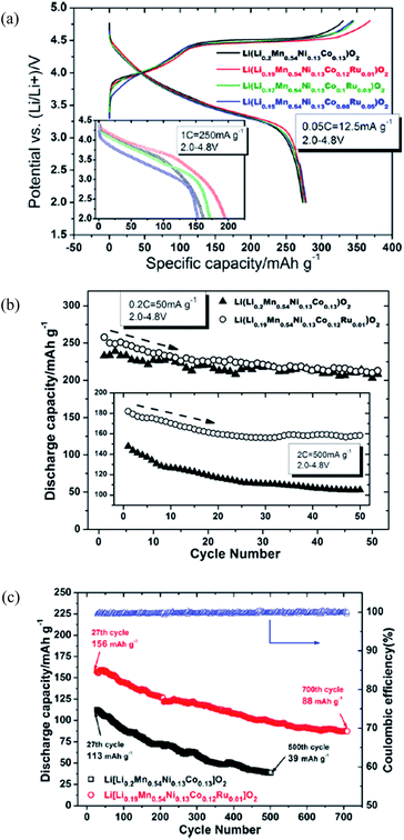 | ||
| Fig. 8 (a) The 1st charge and discharge profiles vs. voltage of Li(Li0.2–xMn0.54Ni0.13Co0.13−xRux)O2 (x = 0, 0.01, 0.03, and 0.05) at 0.05 C rate where inset shows the performance at a high rate of 1 C. (b) Cycling performance of Li(Li0.2Mn0.54Ni0.13Co0.13)O2 and Li(Li0.19Mn0.54Ni0.13Co0.12Ru0.01)O2 at different rates of 0.2 C and 2 C. Testing mode of cycling for inset is 0.05 C for a first cycle followed by 2 C cycles in sequence. T = 25 °C. (c) Cycling performance comparison between pristine Li(Li0.2Mn0.54Ni0.13Co0.13)O2 and modified Li(Li0.19Mn0.54Ni0.13Co0.12Ru0.01)O2 as cathode materials. Testing conditions: 2 C, 2.0–4.8 V, 25 °C.108 Reprinted with permission from © 2012 Elsevier Ltd. | ||
In addition to cation doping, there is some research relative to the substitution of a small amount of F− for O2− anion.106,113 The doped compounds, like Li1+xMyO2−zFz, had a smaller lattice parameter than Li1+xMyO2 because the fluorine substitution changes the oxidation state of transition metal components and more Mn3+ ions with larger ionic radius replace Mn4+ ions for electro-neutrality. The content of fluorine had influence on the electrochemical properties of the doped compounds. On one hand, strong Li–F bonding may hinder Li+ extraction and lead to a low reversible capacity. On the other hand, fluorine doping makes the spinel structure more stable due to the strong M–F bonding, and this is favorable for the cyclic stability. Fig. 9a113 compares the discharge capacity with cycle numbers of Li[Li0.2Ni0.15+0.5zCo0.10Mn0.55−0.5z]O2−zFz materials with different contents of fluorine dopant. The initial discharge capacity slightly decreased with increasing content of fluorine dopant. However, cycling performance was greatly improved, and the capacity retention after 40 cycles of the un-doped material was 79% whereas almost no capacity fade was observed in the F-doped materials. Also, cell impedance was significantly reduced by fluorine doping as shown in Fig. 9b. When adding 10% Co to Li[Li0.2Ni0.2Mn0.6]O2, the ASI dropped significantly from 290 to 150 Ω cm2. The fluorine doping further lowered the impedance of the material to as low as 65 Ω cm2 for Li(Li0.2Ni0.175Co0.1Mn0.525)O1.95F0.05.
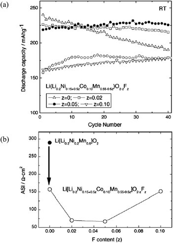 | ||
| Fig. 9 (a) Discharge capacity of Li[Li0.2Ni0.15+0.5zCo0.10Mn0.55−0.5z]O2−zFz cells cycled in the voltage range of 2.0–4.6 V at room temperature. Discharge capacity of Li/Li[Li0.2Ni0.2Mn0.6]O2 (open circles [○]) is also shown for comparison. (b) Average area specific impedance (ASI) at 60–80% state of charge (SOC) measured with graphite/Li[Li0.2Ni0.15+0.5zCo0.10Mn0.55−0.5z]O2−zFz cells as a function of fluorine content. (●) ASI measured with graphite/Li[Li0.2Ni0.2Mn0.6]O2 cell.113 Reprinted with permission from © 2005 Elsevier B.V. | ||
Composites
Physically blending two or more materials may reduce irreversible capacity and increase cathode life and rate performance.114,115 Blending of layered-oxides with spinel materials has been reported extensively and modeling of the improved rate capability of batteries from blended cathodes has also been conducted.114 Blending of LR-NMC materials with intercalation structure materials showed improved pulse power capability, cyclic capability, and capacity retention.116,117 For example, Gallagher et al.116 prepared one composite cathode by blending LiFePO4 with xLi2MnO3·(1 − x)LiMO2 and achieved improved performances, as shown in Fig. 10. The capacity of the blended electrodes was ∼40% higher than that without blending at a high discharge current density of 1.5 A g−1. The capacity value of the blended electrodes was a little lower than the un-blended one in low discharge current density as shown in Fig. 10a, and the coulombic cycle efficiency was 98.1% as shown in Fig. 10b. The improved rate capability was a result of the facile intercalation of Li-ions in the LiFePO4, which showed a stable cycling performance. The stability of LiFePO4 improved the cyclic property of xLi2MnO3·(1 − x)LiMO2. Owing to its low impedance, the LiFePO4 carries the current demanded if the starting potential was low enough or the polarization of the electrode was large enough, which improved the pulse power capability of xLi2MnO3·(1 − x)LiMO2 (Fig. 10c).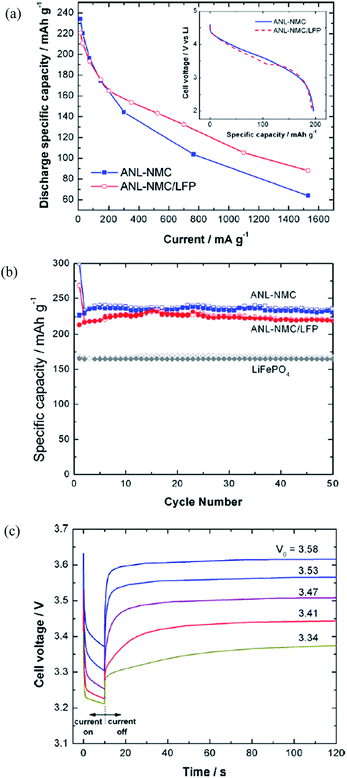 | ||
| Fig. 10 (a) Rate capability for half cells of ANL-NMC and a blended active material configuration of 20 wt% LiFePO4 (LFP) and 80 wt% ANL-NMC. (Inset) C/3 discharge rate at 75 mA g−1; (b) half cell cycling results of LFP, ANL-NMC, and 80 wt% ANL-NMC 20 wt% LFP; (c) 3 C discharge pulses of ANL-NMC/LFP full cells from open-circuit voltages of 3.58, 3.53, 3.47, 3.41, and 3.34 V.116 Reprinted with permission from © 2011 Elsevier B.V. Published by Elsevier B.V. | ||
Gao et al.117 successfully suppressed irreversible capacity loss and increased cycle life by mixing various V2O5 contents with Li[Li0.2Mn0.54Ni0.13Co0.13]O2. In these composites, the Li-free V2O5, with a capacity of about 400 mA h g−1, served as an insertion host to accommodate the Li ions that could not be inserted back into the layered lattice after the first charge as shown in Fig. 11a. The mechanism is: V2O5 + xLi+ + xe− → Li2V2O5. Fig. 11a compares the initial voltage profiles of the Li[Li0.2Mn0.54Ni0.13Co0.13]O2–V2O5 composites with those of Li[Li0.2Mn0.54Ni0.13Co0.13]O2 and V2O5 that were recorded at 12.5 mA g−1. The charge capacity decreased while the discharge capacity increased with increasing V2O5 content; the irreversible capacity loss in the first cycle decreased from 68 mA h g−1 with increasing V2O5 content and reached zero around 11 wt% V2O5. The decrease in irreversible capacity loss was due to the fact that V2O5 served as a host to insert back the Li ions that could not be accommodated into the layered lattice because of the elimination of some of the oxide ion vacancies and Li ion sites at the end of the first charge. The cyclic properties of this composite are shown in Fig. 11b. The irreversible capacity loss decreased from 68 mA h g−1 at 100% Li[Li0.2Mn0.54Ni0.13Co0.13]O2 to 0 around 89 wt% Li[Li0.2Mn0.54Ni0.13Co0.13]O2–11 wt% V2O5. The composite samples exhibited slightly higher capacity fade than the non-blended layered oxide samples and the capacity fade increased with increasing V2O5 content. The composite cathodes with about 10–12 wt% V2O5 exhibited an attractive discharge capacity of close to 300 mA h g−1 with little irreversible capacity loss and good cyclic capability.
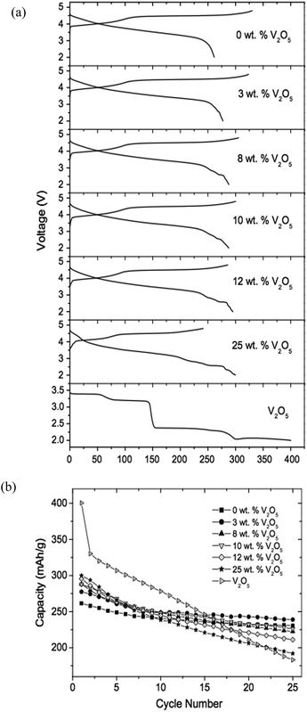 | ||
| Fig. 11 (a) The first charge–discharge profiles of layered Li[Li0.2Mn0.54Ni0.13Co0.13]O2, Li[Li0.2Mn0.54Ni0.13Co0.13]O2–V2O5 composite with various V2O5 contents and V2O5; (b) comparison of the cycleabilities of layered Li[Li0.2Mn0.54Ni0.13Co0.13]O2, V2O5, and Li[Li0.2Mn0.54Ni0.13Co0.13]O2–V2O5 composites with various V2O5 contents.117 Reprinted with permission from © 2008 Elsevier B.V. | ||
Nanostructured materials
In general, LR-NMC materials have large particle sizes, and this may lead to poor rate capabilities. Nanostructured materials have been recently investigated in order to improve the electric performance of LR-NMC materials.30,37 For instance, nanostructured materials may decrease the diffusion length of Li-ion in the insertion/extraction process, which may result in high capacities at high charge–discharge rates. Nanostructured materials may also increase surface/interface storage due to the large contact interface between electrode material and electrolyte. In addition, nanostructured materials may buffer the stresses caused by volume variation occurring during charge–discharge processes, and may alleviate capacity fade and poor rate capability associated with material breaking away into electrolytes.118 However, nanostructured materials may reduce interface stability due to their high specific surface energy. Therefore, how to build nanostructural cathode materials with high energy density and a stable interface with electrolytes is a key issue for current research on LR-NMC nanostructured materials. Recent observations in nanosized insertion materials for LIBs have led to more insight into the impact of the nanosizing. However, it remains difficult to construct a coherent picture.119–121In 2004, Hong et al.37 fabricated a nanocrystalline Li[Li0.2Ni0.2Mn0.6]O2 cathode with mixed particle sizes of 80–200 nm and 1–20 um. The initial discharge capacity was about 288 mA h g−1 when it was cycled in the voltage range of 4.8–2.0 V with a specific current of 20 mA g−1. It showed 43% capacity retention when the current increased from 20 mA g−1 to 900 mA g−1. In 2007, Kim et al.30 prepared nanoplates like Li0.93[Li0.21Co0.28Mn0.51]O2 with a size of 100 nm and a thickness of 20 nm by ion-exchange reaction. The great improvement of the Li0.93[Li0.21Co0.28Mn0.51]O2 cathode was due to its nanoplate-like morphology with a thickness of 20 nm that may achieve short Li diffusion length. Later, Hong's group synthesized nanowire Li[Ni0.25Li0.15Mn0.6]O2 with a diameter of about 30 nm and obtained a first discharge capacity of 311 mA h g−1 at 4 C.122 Wei et al.119 synthesized a crystal habit-tuned nanoplate Li(Li0.17Ni0.25Mn0.58)O2 with a size of 5–9 nm as a cathode using the hydrothermal method. The habit-tuned nanoplate crystal structure parallels the (010) plane and is perpendicular to both [001] and [100] directions. In this structure, the proportion of (010) nanoplates was significantly increased. As shown in Fig. 12, the initial discharge capacity was 200 mA h g−1 under discharge potentials between 2.0 and 4.8 V at 6 C, and retained 80% of the capacity at 0.1 C. After 50 cycles, its capacity was 186 mA h g−1, which showed great cyclic properties and excellent rate capability. At 6 C discharge, the crystal habit-tuned nanoplate material of Li(Li0.17Ni0.25Mn0.58)O2 (HTN-LNMO) has a capacity of 186 mA h g−1 in comparison with 106 mA h g−1 for the conventional thermodynamic equilibrium nanoplate material of Li(Li0.15Ni0.25Mn0.6)O2 (CN-LNMO) and 40 mA h g−1 for Li(Li0.17Ni0.25Mn0.58)O2 (LNMO) big particles. It was obvious that the excellent rate-capability of HTN-LNMO originated from the nanometer-size effect and its unique crystal structure.
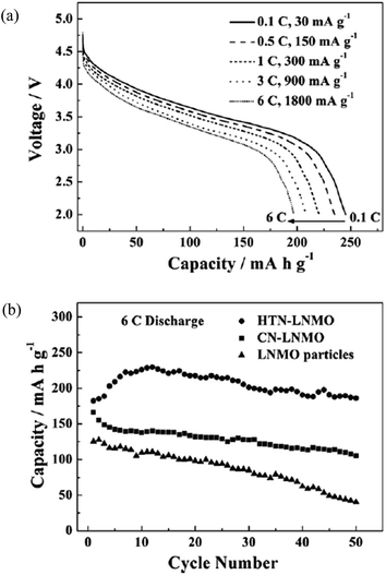 | ||
| Fig. 12 Cycleability and rate capability of HTN-LNMO. (a) Stabilized discharge voltage profiles of HTN-LNMO cycled at different rates: 6, 3, 1, 0.5, and 0.1 C from bottom to top. (b) Discharge capacity at a 6 C rate and cycleability of HTN-LNMO compared with CN-LNMO and LNMO particles.119 Reprinted with permission from © 2010 WILEY-VCH Verlag GmbH & Co. KGaA, Weinheim. | ||
It seems that nanostructured materials, especially single-phase nanostructured materials, may not be an ideal solution to meet the requirements of cathodes for power LIBs. One of the primary reasons is that some of the intrinsic material properties of bulk phase, such as low conductivities, low energy densities at high charge–discharge rates, and weak mechanical stabilities, cannot be simply altered or improved by just transforming them into nanostructured materials. Without surface protection, nanostructured materials may also have more safety concerns due to their high surface reactivity, and may aggravate capacity fade due to aggregation.123,124
Other methods
One new method involves the development of heterogeneous nanostructured materials that are composed of multi-nanocomponents, each of which is tailored to address a specific demand (high Li-ion/electric conductivity, high capacity and structural stability). Potential synergistic effects may be achieved by the interplay between particle shape, properties, and possible association of the individual components, which can be regulated to explore the full potential of the materials in terms of performance.125,126 For instance, the construction of composition gradient from surface to bulk to form core–shell structured particles; a high-capacity Li- and Co-rich cathode material Li1.15[Ni1/3Co1/3Mn1/3]0.85O2 can be used as the core and a Li-rich and Co-free composition Li1.15[Ni1/4Mn3/4]0.85O2 can be used as the shell126 as shown in Fig. 13a. By introducing composition gradient, the performance of core active materials can be maintained, while the less active shell materials can act as a buffer layer and help to improve the material performance at the surface. A synergistic effect of the two materials was reported by the formation of the core–shell architecture. Of note, the core–shell structured cathode material presented improved Li intercalation stability compared to the core, and improved rate capability compared to the shell as shown in Fig. 13b and c. The core–shell cathode had a smaller capacity than that of the shell cathode, but a bigger capacity than that of the core cathode (Fig. 13b). The resistance of the core–shell cell was much smaller than that of the shell cell because of Co, which resulted in improved electric conductivity (Fig. 13c). This result showed that the construction of the core–shell architecture, using Co-containing compounds as the core, was effective at improving rate capability.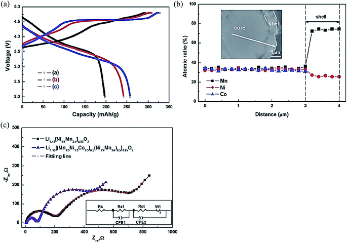 | ||
| Fig. 13 (a) Electron probe microanalyzer (EPMA) compositional change from the cross-section of the core–shell structured Li1.15[(Mn1/3Ni1/3Co1/3)0.5(Ni1/4Mn3/4)0.5]0.85O2 particle. (b) The initial charge–discharge curves of [a] Li1.15[Ni1/3Co1/3Mn1/3]0.85O2, [b] core–shell structured Li1.15[(Mn1/3Ni1/3Co1/3)0.5(Ni1/4Mn3/4)0.5]0.85O2 and [c] Li1.15[Ni1/4Mn3/4]0.85O2 in the voltage range of 2.0–4.8 V at a rate of 0.1 C. (c) Impedance spectra of Li/Li1.15[(Mn1/3Ni1/3Co1/3)0.5(Ni1/4Mn3/4)0.5]0.85O2 cells and Li/Li1.15[Ni1/4Mn3/4]0.85O2 cells.126 Reprinted with permission from © 2012, Royal Society of Chemistry. | ||
Another new approach to improve performance of LR-NMC materials is called pre-cycling treatment.127–129 In 2010, Ito et al.129 studied Li-rich layered cathode Li[Ni0.17Li0.2Co0.07Mn0.56]O2 material with and without pre-cycling treatment; the pre-cycling treatment included increasing the upper potential limit by 0.1 V every two cycles from 4.5 V to 4.8 V. Results showed that the pre-cycling treatment effectively depressed the formation of micro-cracks on the surface of the crystals and the lattice distortion in the crystals. Similarly, in 2012, Nakahara et al.127 fabricated an Fe-containing Li-rich layered oxide Li1.26Mn0.52Fe0.22O2 and evaluated graphite/Li1.26Mn0.52Fe0.22O2 cells after a stepwise pre-cycling treatment. The pre-cycling treatment drastically increased the specific capacity of the Li1.26Mn0.52Fe0.22O2 from 167 to 236 mA h g−1. Other properties such as operation voltage, discharge rate capability, and cycleability also improved with this treatment.
Conclusions and outlook
In this review, the problems with Li-rich layered LR-NMC materials have been reviewed. Some key questions of LR-NMC need to be addressed for this family of materials before their wide application: voltage fade and hysteresis represent significant challenges to the commercialization of these oxides. Mitigating voltage fade will enable the use of these high-energy materials for PHEV and EV applications. In addition, the charge–discharge mechanism of such materials is still not clear. Moreover, the problems of large initial irreversible capacity loss and inferior rate and cyclic capabilities still exist and need to be further studied. Lastly, these materials have low tap density and it is difficult to obtain dense materials. Therefore, researchers need to find ways to increase energy density and, at the same time, reduce production cost.However, the conventional strategies discussed in this paper have limited effects for improving the whole performance of such materials. For example, the mechanisms of voltage fade and hysteresis are still not clear and there are no effective ways to control them. The following ideas, which may lead to better understanding and improvements of LMR-NMC, may be considered:
(1) Solve structural and electrochemical performance problems from structural designing and electrochemical characterization. For instance, develop an atomic-level model to capture the essential electrochemical observations associated with voltage fade and hysteresis to understand the following questions: (a) what are the effects of domains and domain size? (b) How does the transition metal and Li ordering influence the electrochemical performance? (c) How can the transition metal and Li return to the octahedral positions in LMR-NMC? (d) How do the transition metal and Li migrate to a new octahedral position? (e) How can the transition metal and Li be trapped in the octahedral positions thereby increasing cell impedance? (f) Does the H+ insert into the lattice of the structure during discharge?
(2) Understand oxygen loss mechanism and corresponding formation of defect sites. For example, develop a kind of redox shuttle electrolyte additive to stabilize SEI and to capture the intermediate oxygen anions released from LR-NMC lattice during discharge. Oxygen release is one of the biggest safety issues because of the high voltage applied. Overcharge of LR-NMC based batteries can lead to side reactions, rapid temperature elevation, and even explosion. On the overcharged cathode surface, the redox shuttle molecule is oxidized to its cation form which, via diffusion across the electrolyte, would be reduced back to its original or reduced state on the surface of the anode. The reduced form would then diffuse back to the cathode and oxidize again. The “oxidation–diffusion–reduction–diffusion” cycle can be repeated continuously due to the reversible nature of the redox shuttle to shunt the overcharge current. On the other hand, these additives should capture the intermediate oxygen anions or radicals before forming oxygen.
(3) Form unique nano-layered porous cathodes using electrostatic layer-by-layer self-assembly to enhance energy/power densities and pulse power densities. Nano-layered cathodes can be fabricated on aluminum current collectors by alternate adsorption of oppositely charged active materials and highly conductive additive materials. Based on our previous studies130–134, we expect electrostatic layer-by-layer self-assembly will allow tuning of the interface properties between cathode active particles and additive polymers, and cathode active particles and electrolyte. Their porous structure may act as reservoirs for liquid electrolytes capable of fast Li-ion conduction, and their highly intertwined component materials may facilitate electric conductivity and Li-ion transport. Such nano-layered structures may also provide large reactive interfacial areas that allow convenient incorporation and manipulation of active materials into specific nano-layers. The nano-layer/electrolyte interfaces can be tuned to enhance electronic and ionic conduction across the interfaces therefore leading to maximized efficiency of active materials. What's more, the energy density may be improved without binder and the pulse power may be improved by tuning the thickness of cathode nano-layers.
Acknowledgements
The authors wish to acknowledge the financial support of the West Virginia Higher Education Policy Commission Division of Science Research Challenge Grant program. The authors thank Suzanne Danley for proofreading.References
- J. B. Goodenough and K. S. Park, J. Am. Chem. Soc., 2013, 135, 1167 CrossRef CAS PubMed.
- M. Armand and J. M. Tarascon, Nature, 2008, 451, 652 CrossRef CAS PubMed.
- S. Akao, M. Yamada, T. Kodera, K. Myoujin and T. Ogihara, Adv. Mater. Sci. Eng., 2011, 2011, 1 CrossRef PubMed.
- J. B. Goodenough and Y. Kim, Chem. Mater., 2010, 22, 587 CrossRef CAS.
- M. S. Whittingham, Chem. Rev., 2004, 104, 4271 CrossRef CAS.
- T. Watabe and M. Mori, LIBs materials industry, 2011, 26 January, p. 22 Search PubMed.
- http://www.greencarcongress.com/2012/02/envia-20120227.html, 2013.
- Working Document of the NPC Future Transportation Fuels Study, 2012.
- M. M. Thackeray, C. S. Johnson, J. T. Vaughey, N. Li and S. A. Hackne, J. Mater. Chem., 2005, 15, 2257 RSC.
- M. N. Ates, Q. Jia, A. Shah, A. Busnaina, S. Mukerjee and K. M. Abraham, J. Electrochem. Soc., 2014, 161, A290 CrossRef CAS PubMed.
- C. S. Johnson, N. Li, C. Lefief, J. T. Vaughey and M. M. Thackeray, Chem. Mater., 2008, 20, 6095 CrossRef CAS.
- K. Jarvis, Z. Deng, L. Allard, A. Manthiram and P. Ferreira, Microsc. Microanal., 2011, 17, 1578 CrossRef.
- C. S. Johnson, S. D. Korte and J. T. Vaughey, et al., J. Power Sources, 1999, 81–82, 491 CrossRef CAS.
- A. Boulineau, L. Croguennec, C. Delmas and F. Weill, Chem. Mater., 2009, 21, 4216 CrossRef CAS.
- G. Yang, H. Ji, P. Gao, A. Hong, H. Ding, S. Roy, J. Pinto and X. Jiang, J. Electrochem. Soc., 2011, 158, A1071 CrossRef CAS PubMed.
- J. Jiang and J. R. Dahn, Electrochim. Acta, 2005, 50, 4778 CrossRef CAS PubMed.
- J. Jiang and J. R. Dahn, Electrochim. Acta, 2006, 51, 3413 CrossRef CAS PubMed.
- Z. H. Lu, D. D. MacNeil and J. R. Dahn, Electrochem. Solid-State Lett., 2001, 4, A191 CrossRef CAS PubMed.
- Z. H. Lu, L. Y. Beaulieu, R. A. Donaberger, C. L. Thomas and J. R. Dahn, J. Electrochem. Soc., 2002, 149, A778 CrossRef CAS PubMed.
- R. Santhanam, P. Jones, A. Sumana and B. Rambabu, J. Power Sources, 2010, 195, 7391 CrossRef CAS PubMed.
- S.-H. Kang, J. Kim, D. Abraham, M. E. Stoll, Y.-K. Sun and K. Amine, J. Power Sources, 2002, 112, 41 CrossRef CAS.
- K.-S. Park, M. H. Cho, S. J. Jin, C. H. Song and K. S. Nahm, J. Power Sources, 2005, 146, 281 CrossRef CAS PubMed.
- M. Tabuchi, Y. Nabeshima, K. Ado, M. Shikano, H. Kageyama and K. Tatsumi, J. Power Sources, 2007, 174, 554 CrossRef CAS PubMed.
- C. Pan, Y. J. Lee, B. Ammundsen and C. P. Grey, Chem. Mater., 2002, 14, 2289 CrossRef CAS.
- Z. H. Lu, Z. H. Chen and J. R. Dahn, Chem. Mater., 2003, 15, 3214 CrossRef CAS.
- C. H. Lei, J. Bareno, J. G. Wen, I. Petrov, S.-H. Kang and D. P. Abraham, J. Power Sources, 2008, 178, 422 CrossRef CAS PubMed.
- K. A. Jarvis, Z. Deng, L. F. Allard, A. Manthiram and P. J. Ferreira, Chem. Mater., 2011, 23, 3614 CrossRef CAS.
- J.-S. Kim, C. S. Johnson, J. T. Vaughey and M. M. Thackeray, Chem. Mater., 2004, 16, 1996 CrossRef CAS.
- J. Bareno, M. Balasubramanian, S. H. Kang, J. G. Wen, C. H. Lei, S. V. Pol, I. Petrov and D. P. Abraham, Chem. Mater., 2011, 23, 2039 CrossRef CAS.
- Y.-J. Kim, Y. Hong, M. G. Kim and J. Cho, Electrochem. Commun., 2007, 9, 1041 CrossRef CAS PubMed.
- H. Yu, H. Kim, Y. Wang, P. He, D. Asakura, Y. Nakamura and H. Zhou, Phys. Chem. Chem. Phys., 2012, 14, 6584 RSC.
- X. Yu, Y. Lyu, L. Gu, H. Wu, S. Bak, Y. Zhou, K. Amine, S. N. Ehrlich, H. Li, K. Nam and X. Yang, Adv. Energy Mater., 2014, 4, 1300950 Search PubMed.
- S.-H. Yu, T. Yoon, J. Mun, S. Park, Y.-S. Kang, J.-H. Park, S. M. Oh and Y.-E. Sung, J. Mater. Chem. A, 2013, 1, 2833 CAS.
- J. Kikkawa, T. Akita, M. Tabuchi, M. Shikano, K. Tatsumi and M. Kohyama, Electrochem. Solid-State Lett., 2008, 11, A183 CrossRef CAS PubMed.
- B. Song, Z. Liu, M. Lai and L. Lu, Phys. Chem. Chem. Phys., 2012, 14, 12875 RSC.
- N. Yabuuchi, K. Yoshii, S.-T. Myung, I. Nakai and S. Komaba, J. Am. Chem. Soc., 2011, 133, 4404 CrossRef CAS PubMed.
- Y.-S. Hong, Y. J. Park, K. S. Ryu, S. H. Chang and M. G. Kim, J. Mater. Chem., 2004, 14, 1424 RSC.
- Y. Wu and A. Manthiram, Electrochem. Solid-State Lett., 2007, 10, A151 CrossRef CAS PubMed.
- Y. Koyama, I. Tanakaa, M. Nagao and R. Kanno, J. Power Sources, 2009, 189, 798 CrossRef CAS PubMed.
- L. Yu, W. Qiu, F. Lian, J. Huang and X. Kang, J. Alloys Compd., 2009, 471, 317 CrossRef CAS PubMed.
- M. Gu, I. Belharouak, J. Zheng, H. Wu, J. Xiao, A. Genc, K. Amine, S. Thevuthasan, D. R. Baer, J. Zhang, N. D. Browning, J. Liu and C. Wang, ACS Nano, 2013, 7, 760 CrossRef CAS PubMed.
- A. R. Armstrong, M. Holzapfel, P. Novák, C. S. Johnson, S. H. Kang, M. M. Thackeray and P. G. Bruce, J. Am. Chem. Soc., 2006, 128, 8694 CrossRef CAS PubMed.
- P. Xiao, Z. Q. Deng, A. Manthiram and G. Henkelman, J. Phys. Chem. C, 2012, 116, 23201 CAS.
- T. A. Arunkumar, Y. Wu and A. Manthiram, Chem. Mater., 2007, 19, 3067 CrossRef CAS.
- A. D. Robertson and P. G. Bruce, Chem. Commun., 2002, 2790 RSC.
- A. R. Armstrong, A. D. Robertson and P. G. Bruce, J. Power Sources, 2005, 146, 2275 Search PubMed.
- C. S. Johnson, N. Li, C. Lefief and M. M. Thackeray, Electrochem. Commun., 2007, 9, 787 CrossRef CAS PubMed.
- B. Li, Q. Wang, Y. Zhang, Z. Song and D. Yang, Int. J. Electrochem. Sci., 2013, 8, 5396 CAS.
- M. M. Thackeray, S.-H. Kang, C. S. Johnson, J. T. Vaughey, R. Benedeka and S. A. Hackney, J. Mater. Chem., 2007, 17, 3112 RSC.
- C. Yu, G. Li, X. Guan, J. Zheng, D. Luo and L. Li, Phys. Chem. Chem. Phys., 2012, 14, 12368 RSC.
- A. D. Robertson and P. G. Bruce, Electrochem. Solid-State Lett., 2004, 7, A294 CrossRef CAS PubMed.
- S. E. Trask, Y. Li, J. J. Kubai, M. Bettge, B. J. Polzin, Y. Zhu, A. N. Jansen and D. P. Abraham, J. Power Sources, 2014, 259, 233 CrossRef CAS PubMed.
- K. G. Gallagher, J. R. Croy, M. Balasubramanian, M. Bettge, D. P. Abraham, A. K. Burrell and M. M. Thackeray, Electrochem. Commun., 2013, 33, 96 CrossRef CAS PubMed.
- M. Bettge, Y. Li, K. G. Gallagher, Y. Zhu, Q. Wu, W. Lu, I. Bloom and D. P. Abraham, J. Electrochem. Sci. Technol., 2013, 160, A2046 CrossRef CAS PubMed.
- I. Bloom, L. Trahey, A. Abouimrane, I. Belharouak, H. Wu, W. Lu, D. P. Abraham, M. Bettge, J. Elam, X. Meng and A. Burrell, J. Power Sources, 2013, 249, 509 CrossRef PubMed.
- J. R. Croy, et al., J. Electrochem. Sci. Technol., 2014, 161, A318 CrossRef CAS PubMed.
- Y.-S. Hong, Y. J. Park, X. Wu, K. S. Ryu and S. H. Chang, Electrochem. Solid-State Lett., 2003, 6, A166 CrossRef CAS PubMed.
- S.-H. Kang, Y.-K. Sun and K. Amine, Electrochem. Solid-State Lett., 2003, 6, A183 CrossRef CAS PubMed.
- Y. Liu and S. Liu, Ionics, 2013, 19, 477 CrossRef CAS.
- S. H. Kang and K. Amine, J. Power Sources, 2003, 124, 533 CrossRef CAS.
- K. Ozawa, Y. Nakao, T. Mochiku, Z. Cheng, L. Wang, H. Iwai, Y. Tsuchiya, H. Fujii and N. Igawa, J. Electrochem. Soc., 2012, 159, A300 CrossRef CAS PubMed.
- J. Li, R. Klöpsch, M. C. Stan, S. Nowak, M. Kunze, M. Winter and S. Passerini, J. Power Sources, 2011, 196, 4821 CrossRef CAS PubMed.
- Y. N. Ko, J.-H. Kim, J.-K. Lee, Y. C. Kanga and J.-H. Lee, Electrochim. Acta, 2012, 69, 345 CrossRef CAS PubMed.
- Y.-J. Hong, J.-H. Kim, M.-H. Kim and Y.-C. Kang, Mater. Res. Bull., 2012, 47, 2022 CrossRef CAS PubMed.
- X. Zhang, C. Yu, X. Huang, J. Zheng, X. Guan, D. Luo and L. Li, Electrochim. Acta, 2012, 81, 233 CrossRef CAS PubMed.
- S. J. Shi, J. P. Tu, Y. Y. Tang, Y. X. Yu, Y. Q. Zhang, X. L. Wang and C. D. Gu, J. Power Sources, 2013, 228, 14 CrossRef CAS PubMed.
- C. Yu, G. Li, X. Guan, J. Zheng, L. Li and T. Chen, Electrochim. Acta, 2012, 81, 283 CrossRef CAS PubMed.
- Z. Li, K. Zhu, Y. H. Wang, C. Z. Wang, G. Chen and Y. J. Wei, Sci. Adv. Mater., 2012, 4, 843 CrossRef CAS PubMed.
- R. Santhanam and B. Rambabu, Int. J. Electrochem. Sci., 2009, 4, 1770 CAS.
- X. Huang, Q. Zhang, H. Chang, J. Gan, H. Yue and Y. Yang, J. Electrochem. Soc., 2009, 156, A162 CrossRef CAS PubMed.
- M. Tabuchi, Y. Nabeshimaa, T. Takeuchia, H. Kageyamaa, K. Tatsumia, J. Akimotob, H. Shibuyac and J. Imaizumi, J. Power Sources, 2011, 196, 3611 CrossRef CAS PubMed.
- W. C. West, J. Soler and B. V. Ratnakumar, J. Power Sources, 2012, 204, 200 CrossRef CAS PubMed.
- M. Tabuchi, Y. Nabeshima, T. Takeuchi, H. Kageyama, J. Imaizumi, H. Shibuya and J. Akimoto, J. Power Sources, 2013, 221, 427 CrossRef CAS PubMed.
- J. R. Croy, S. H. Kang, M. Balasubramanian and M. M. Thackeray, Electrochem. Commun., 2011, 13, 1063 CrossRef CAS PubMed.
- J. Lin, D. Mu, Y. Jin, B. Wu, Y. Ma and F. Wu, J. Power Sources, 2013, 230, 76 CrossRef CAS PubMed.
- F. Wu, H. Lu, Y. Su, N. Li, L. Bao and S. Chen, J. Appl. Electrochem., 2010, 40, 783 CrossRef CAS PubMed.
- Z. Chen, Y. Qin, K. Amine and Y.-K. Sun, J. Mater. Chem., 2010, 20, 7606 RSC.
- J.-H. Ryu, B.-G. Park, S.-B. Kim and Y.-J. Park, J. Appl. Electrochem., 2009, 39, 1059 CrossRef CAS.
- Y. Wu and A. Manthiram, Solid State Ionics, 2009, 180, 50 CrossRef CAS PubMed.
- Y. Deng, S. Liu and X. Liang, J. Solid State Electrochem., 2013, 17, 1067 CrossRef CAS PubMed.
- S. T. Myung, K. Izumi and S. Komaba, et al., J. Phys. Chem. C, 2007, 111, 4061 CAS.
- J. M. Zheng, J. Li, Z. R. Zhang, X. J. Guo and Y. Yang, Solid State Ionics, 2008, 179, 1794 CrossRef CAS PubMed.
- Y. Wu and A. Manthiram, Electrochem. Solid-State Lett., 2006, 9, A221 CrossRef CAS PubMed.
- S. J. Shi, J. P. Tu, Y. Y. Tang, X. Y. Liu, Y. Q. Zhang, X. L. Wang and C. D. Gu, Electrochim. Acta, 2013, 88, 671 CrossRef CAS PubMed.
- Y. Zhao, C. Zhao, H. Feng, Z. Sun and D. Xia, Electrochem. Solid-State Lett., 2011, 14, A1 CrossRef CAS PubMed.
- X. Guan, B. Ding, X. Liu, J. Zhu, C. Mi and X. Zhang, J. Solid State Electrochem., 2013, 17, 2087 CrossRef CAS.
- K.-J. Rosina, M. Jiang, D. Zeng, E. Salager, A.-S. Best and C.-P. Grey, J. Mater. Chem., 2012, 22, 20602 RSC.
- G. R. Li, X. Feng, Y. Ding, S. H. Ye and X. P. Gao, Electrochim. Acta, 2012, 78, 308 CrossRef CAS PubMed.
- K. Yang, L. Fan, J. Guo and X. Qu, Electrochim. Acta, 2012, 63, 363 CrossRef CAS PubMed.
- H. Deng, I. Belharouak, C. S. Yoon, Y. K. Sun and K. Amine, J. Electrochem. Soc., 2010, 157, A1035 CrossRef CAS PubMed.
- S.-H. Lee, B.-K. Koo, J.-C. Kim and K.-M. Kim, J. Power Sources, 2008, 184, 276 CrossRef CAS PubMed.
- Q. Y. Wang, J. Liu and A. V. Murugan, et al., J. Mater. Chem., 2009, 19, 4965 RSC.
- B. Liu, Q. Zhang, S. He, Y. Sato, J. Zheng and D. Li, Electrochim. Acta, 2011, 56, 6748 CrossRef CAS PubMed.
- S. H. Kang and M. M. Thackeray, Electrochem. Commun., 2009, 11, 748 CrossRef CAS PubMed.
- Q. Q. Qiao, H. Z. Zhang, G. R. Li, S. H. Ye, C. W. Wang and X. P. Gao, J. Mater. Chem. A, 2013, 1, 5262 CAS.
- Y. J. Kang, J. H. Kim and S. W. Lee, et al., Electrochim. Acta, 2005, 50, 4784 CrossRef CAS PubMed.
- S. Myung, K. Amine and Y. Sun, J. Mater. Chem., 2010, 20, 7074 RSC.
- J. S. Kim, C. S. Johnson, J. T. Vaughey and M. M. Thackeray, J. Power Sources, 2006, 153, 258 CrossRef CAS PubMed.
- Y. W. Y. Denis, Y. Katsunori and N. Hiroshi, J. Electrochem. Soc., 2010, 157, A1177 CrossRef PubMed.
- A. Abouimrane, O. C. Compton and H. Deng, et al., Electrochem. Solid-State Lett., 2011, 14, A126 CrossRef CAS PubMed.
- H. Z. Zhang, Q. Q. Qiao, G. R. Li, S. H. Ye and X. P. Gao, J. Mater. Chem., 2012, 22, 13104 RSC.
- J. Zheng, S. Deng, Z. Shi, H. Xu, H. Xu, Y. Deng, Z. Zhang and G. Chen, J. Power Sources, 2013, 221, 108 CrossRef CAS PubMed.
- M. Chi, C. Fell, B. Xu and S. Meng, Microsc. Microanal., 2011, 17, 1574 CrossRef.
- Z. Tang, Z. Wang, X. Li and W. Peng, J. Power Sources, 2012, 204, 187 CrossRef CAS PubMed.
- J. H. Kim, C. W. Park and Y. K. Sun, Solid State Ionics, 2003, 164, 43 CrossRef CAS PubMed.
- O. Sha, Z. Tang, S. Wang, W. Yuan, Z. Qiao, Q. Xu and L. Ma, Electrochim. Acta, 2012, 77, 250 CrossRef CAS PubMed.
- S. H. Park and Y. K. Sun, J. Power Sources, 2003, 119–121, 161 CrossRef CAS.
- B. Song, M. Lai and L. Lu, Electrochim. Acta, 2012, 80, 187 CrossRef CAS PubMed.
- L. Jiao, M. Zhang, H. Yuan, M. Zhao, J. Guo, W. Wang, X. Zhou and Y. Wang, J. Power Sources, 2007, 167, 178 CrossRef CAS PubMed.
- Q. Liu, K. Du, G. Hu, Z. Peng, Y. Cao and W. Liu, Solid State Ionics, 2012, 227, 23 CrossRef CAS PubMed.
- A. Boulineau, L. Simonin, J. Colin, E. Canévet, L. Daniel and S. Patoux, Chem. Mater., 2012, 24, 3558 CrossRef CAS.
- M.-K. Song, S. Park, F. M. Alamgir, J. Cho and M. Liu, Mater. Sci. Eng., R, 2011, 72, 203 CrossRef PubMed.
- S. H. Kang and K. J. Amine, J. Power Sources, 2005, 146, 654–656 CrossRef CAS PubMed.
- P. M. Gomadam, D. R. Merritt, E. R. Scott, C. L. Schmidt, P. M. Skarstad and J. W. Weidner, J. Power Sources, 2007, 174, 872 CrossRef CAS PubMed.
- A. Manthiram and W. Choi, Electrochem. Solid-State Lett., 2007, 10, A228 CrossRef CAS PubMed.
- K. G. Gallagher, S.-H. Kang, S. Park and S.-Y. Han, J. Power Sources, 2011, 196, 9702 CrossRef CAS PubMed.
- J. Gao, J. Kim and A. Manthiram, Electrochem. Commun., 2009, 11, 84 CrossRef CAS PubMed.
- R. Liu, J. Duay and S. Lee, Chem. Commun., 2010, 47, 1384 RSC.
- G. Wei, X. Lu, F. Ke, L. Huang, J. Li, Z. Wang, Z. Zhou and S. Sun, Adv. Mater., 2010, 22, 4364 CrossRef CAS PubMed.
- Y. J. Wei, K. Nikolowski, S. Y. Zhan, H. Ehrenberg, S. Oswald, G. Chen, C. Z. Wang and H. Chen, Electrochem. Commun., 2009, 11, 2008 CrossRef CAS PubMed.
- C. Zhao, W. Kang, Q. Xue and Q. Shen, J. Nanopart. Res., 2012, 14, 1240 CrossRef.
- M. G. Kim, M. Jo and Y. S. Hong, et al., Chem. Commun., 2009, 218 RSC.
- R. Liu, J. Duay and S. Lee, Chem. Commun., 2011, 47, 1384 RSC.
- Y. Sun, S. Myung, B. Park, J. Prakash, I. Belharouak and K. Amine, Nat. Mater., 2009, 8, 320 CrossRef CAS PubMed.
- Z. Chen, D.-J. Lee, Y.-K. Sun and K. Amine, MRS Bull., 2011, 36, 498 CrossRef.
- X. Yang, X. Wang, Q. Wei, H. Shu, L. Liu, S. Yang, B. Hu, Y. Song, G. Zou, L. Hu and L. Yi, J. Mater. Chem., 2012, 22, 19666 RSC.
- K. Nakahara, M. Tabuchi, S. Kuroshima, A. Toda, K. Tanimoto and K. Nakano, J. Electrochem. Soc., 2012, 159, A1398 CrossRef CAS PubMed.
- A. Watanabe, F. Matsumoto, M. Fukunishi, G. Kobayashi, A. Ito, M. Hatano, Y. Ohsawa and Y. Sato, J. Electrochem. Sci. Technol., 2011, 80, 561 Search PubMed.
- A. Ito, D. Li, Y. Sato, M. Arao, M. Watanabe, M. Hatano, H. Horie and Y. Ohsawa, J. Power Sources, 2010, 195, 567 CrossRef CAS PubMed.
- B. Li, B. Jiang, D. J. Fauth, M. L. Gray, H. W. Pennline and G. A. Richards, Chem. Commun., 2011, 47, 1719 RSC.
- B. Jiang, V. Kish, D. J. Fauth, M. L. Gray, H. W. Pennline and B. Li, Int. J. Greenhouse Gas Control, 2011, 5, 1170 CrossRef CAS PubMed.
- Q. Zhao, H. Li and B. Li, J. Mater. Res., 2011, 26, 347 CrossRef CAS PubMed.
- Q. Zhao and B. Li, J. Nanomed. Nanotechnol., 2008, 4, 302 CrossRef CAS PubMed.
- F. Likibi, B. Jiang and B. Li, J. Mater. Res., 2008, 23, 3222 CrossRef CAS.
| This journal is © The Royal Society of Chemistry 2014 |


