One pot green synthesis of polyaniline coated gold nanorods and its applications†
Sanjoy Mondala,
Utpal Ranaa,
Rama Ranjan Bhattacharjeeb and
Sudip Malik*a
aPolymer Science Unit, Indian Association for the Cultivation of Science, 2A and 2B Raja S. C. Mullick Road, Jadavpur, Kolkata 700032, India. E-mail: psusm2@iacs.res.in
bPSG Institute of Advanced Studies, Avinashi Road, Peelamedu, Coimbatore, Tamil Nadu 641004, India
First published on 15th October 2014
Abstract
Morphology controlled high aspect ratio worm-like polyaniline (PANI) layer coated Au-nanostructures (Au/PANI) have been successively synthesized by in situ polymerisation techniques using aniline as a monomer with HAuCl4 as an oxidising agent in the absence and presence of citric acid (CA). Synthesized composites were characterized by HRTEM, FESEM, XRD, XPS, UV-vis and FTIR study. Spherical morphologies are seen in the absence of CA and Au nanoparticles are coated by a PANI thin layer with ∼30 nm thickness. In the presence of CA, as well as depending upon the CA to aniline molar ratio, morphology varies from irregular assembly to regular fiber to spherical-like nanostructures. The nanostructures show fibrous morphology with an average diameter of ∼100 nm and lengths of more than 5 μm when CA to aniline molar ratios are 1.0 and 0.2. When the ratios are 2.0 and 0.1, the nanostructure represents the granular-like morphology. Nanofiber formation takes place by the assembly of the CA capped tiny Au-nanorods in the presence of aniline during the polymerisation, and all Au-nanorods are finely coated by a PANI thin layer of ∼5 nm thickness. Importantly, fibrous Au/PANI nanostructures show superior catalytic activity compared to spherical/irregular Au/PANI nanostructures towards the reduction of toxic aromatic nitro compounds like 4-nitrophenol (4-NP), 4-nitroaniline (4-NA), 2,4-dinitrophenol (2,4-DNP) and 2,4,6-trinitrophenol (2,4,6-TNP). This is because of the coating thickness of PANI over Au-nanoparticles in fibrous Au/PANI nanostructures as well as enhanced surface area.
Introduction
In recent years, the fabrication of nanostructures with controlled morphology is challenging to scientists because dimensionality plays an important role for determining material properties. One-dimensional (1D) nanostructure, including nanorods, fibers, wires and tubes, have attracted more attention due to their unique optical, electronic properties, resulting in great attention in many potential applications like field effect transistors,1,2 quantum wire lasers,3 electronic memory devises,4,5 and catalysts.6,7 Making nanostructure materials containing electrically conducting polymers and metal nanoparticles are attractive fields of research nowadays due to their important physical properties and potential applications in molecular memory devices, batteries, display devices, and bio-chemistry.8 Among all conductive polymers, PANI is the most popular conductive polymeric material9,10 because of its easy synthesis, good environmental stability,11 low cost of the raw/starting materials, large range of conductivity, and high thermal stability. Among the metal nanoparticles, Au-nanoparticles have been extensively studied in the scientific community because of its exclusive catalytic12–14 and unique optical properties.13 The in situ technique is one of the best techniques for synthesis because (a) single step reaction, (b) high percentage of yield and (c) no need for step by step purification.15Formation of Au/PANI nanostructures by the soft template method17–19 involves going through a series of steps such as chemical reactions, nucleation and precipitation. Each and every step is influenced by many experimental parameters like external materials (additives/dopants), concentration of starting and any externally applied materials, reaction temperature, and reaction time. Actually, the nucleation step has a vital role for formation of nanospheres and nanofibers of PANI in the solution state.20,21 Homogeneous nucleation reveals the nanofiber morphology of PANI in bulk solutions while heterogeneous nucleation leads to irregular or/and nanosphere-like morphology of PANI.20 The aspect ratio of Au/PANI nanostructures also depends on the concentration of controlling agent, reaction temperature, pH and reaction time.10,16
Here we report a simple solution mixing in situ method for Au/PANI nanostructure synthesis at room temperature using HAuCl4, CA and aniline. HAuCl4 acts as an oxidising agent, as well as proton donor to PANI, and CA acts as a capping agent for Au-nanoparticles synthesis as well as a secondary dopant for PANI (ES). The morphology of the nanostructure is tuned by changing the molar ratio of CA to aniline. Nanostructures have regular nanofiber-like (worm) morphology when the CA to aniline molar ratio is 1.0 to 0.2 and irregular agglomerated morphology when 2.0 to 0.1. The mechanism of the nanostructure formation was also established from HRTEM studies and results showed that CA plays an important role for worm-like nanostructure formation. Optimisation of the reaction conditions for nanofiber formation was performed by time dependent UV-vis and HRTEM studies. The synthesized nanostructure showed good catalytic efficiency and recyclability in the reduction of several nitro compounds in an aqueous medium. In addition, the catalytic efficiency of worm-like nanofibers is much more than that of the agglomerated structures under identical conditions.
Experimental details
Materials
Aniline was distilled under reduced pressure and stored at 5 °C in a dark place and sodium borohydride (NaBH4) was purchased from Merck chemicals. Au(III) chloride trihydrate (HAuCl4·3H2O, ACS reagent, ≥49.0% Au basis) and citric acid (ACS reagent, ≥99.5%) were purchased from Sigma-Aldrich and used without further purification. The nitro aromatics compounds (4-nitrophenol, 2,4-dinitrophenol, 2,4,6-trinitrophenol and 4-nitroaniline) were purchased from Loba Chemicals, Mumbai. All solutions were prepared in deionised water (18 MΩ cm, Millipore Milli Q water).Instruments
To observe the surface morphology of composites, small amounts of prepared composites were dispersed in Milli Q water then drop casted on a glass cover slip and dried at room temperature. We used a JEOL, JSM 6700F instrument operating at 5 kV. To reduce the surface potential, samples were coated with platinum for 90 s due to the accumulation of electrostatic charge.The electron microscopy of Au/PANI nanostructures was carried out using HRTEM (JEOL, 2010EX), and images were taken using a CCD at an accelerating voltage of 200 kV. Samples were spread over a 200 mesh Cu-grid coated with a holey carbon support film.
UV-vis spectra of Au/PANI samples were recorded using a Hewlett–Packard UV-vis spectrophotometer (model 8453) in a 1.0 cm path length quartz cell.
XRD measurements were performed using a Bruker AXS diffractometer (D8 advance) using CuKα radiation (λ = 1.54 Å), a generator voltage of 40 kV and a current of 40 mA. The scanning range of the samples 2θ = 15–85°, and the scan rate was 1 s per step with a step width of 0.02°.
The FTIR spectra were obtained in a FTIR-8400S instrument (Shimadzu) using KBr pellets of the samples.
XPS was performed using a focused monochromatized Mg-Kα X-ray source (1253.6 eV) in an Omicron Nano-Technology 0571 XPS instrument.
Synthesis of Au/PANI@0.0 composite
To an aqueous solution of HAuCl4 (1 mM, 10 mL) in a culture tube, 100 μL of distilled aniline was added (to maintain a HAuCl4 to aniline molar ratio = 1![[thin space (1/6-em)]](https://www.rsc.org/images/entities/char_2009.gif) :
:![[thin space (1/6-em)]](https://www.rsc.org/images/entities/char_2009.gif) 1) and stirred constantly for 30 min, and then maintained in a dark place without stirring for 12 h to obtain a spherical-like composite called Au/PANI@0.0 composite.
1) and stirred constantly for 30 min, and then maintained in a dark place without stirring for 12 h to obtain a spherical-like composite called Au/PANI@0.0 composite.
Synthesis of CA stabilized Au seed solution
In a typical experiment, 10 mL of 1 mM CA aqueous solution was mixed with 1 mM HAuCl4 aqueous solution (v/v = 1![[thin space (1/6-em)]](https://www.rsc.org/images/entities/char_2009.gif) :
:![[thin space (1/6-em)]](https://www.rsc.org/images/entities/char_2009.gif) 1) in a culture tube equipped with a magnetic stirrer at room temperature (25 °C). After 1 h, the solution colour changed from greenish yellow to transparent pinkish violate, and this solution (Au-60) was considered as an active seed solution for Au/PANI formation.
1) in a culture tube equipped with a magnetic stirrer at room temperature (25 °C). After 1 h, the solution colour changed from greenish yellow to transparent pinkish violate, and this solution (Au-60) was considered as an active seed solution for Au/PANI formation.
Synthesis of Au/PANI@2.0, Au/PANI@1.0, Au/PANI@0.2 and Au/PANI@0.1 composite
To make Au/PANI nanofiber, 20 mL Au-60 aqueous solution was taken in a culture tube, and then different amounts (in μL) of distilled aniline monomer were added (Table S1†) to the Au-60 aqueous solution with constant stirring until the dissolution of the aniline at room temperature (25 °C). After adding aniline, the solution colour changed from pinkish violate to deep blue to black immediately, indicating that the Au/PANI composite started to form. The reaction mixture was kept in a dark place without stirring for 12 h. Finally products were collected by centrifugation at 8000 rpm, washed with water several times, and finally dried under vacuum at 60 °C to obtain a dark powder of Au/PANI-composites.Catalytic activity towards nitro compound reduction
For monitoring the reduction process, yellow aqueous solutions of aromatic nitro phenol compounds (4-nitrophenol, 4-nitroaniline, 2,4-di-nitrophenol, 2,4,6-tri-nitrophenols) of 1 mM and 3 mM concentration of ice cold NaBH4 solution were prepared. To a diluted solution of nitrophenol (100 μL of 4-nitrophenol and 2 mL water) taken in a quartz UV cell, water dispersed Au/PANI composite (0.3 wt%) was subsequently added and immediately 100 μL of 3 mM NaBH4 solution was poured. Solutions were quickly subjected to UV-vis measurement for monitoring the reduction processes.6,7,22 Same procedure were followed for 4-NA, 2,4-DNP and 2,4,6-TNP.Results and discussion
Morphological studies
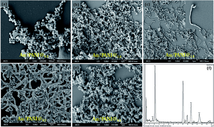
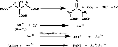
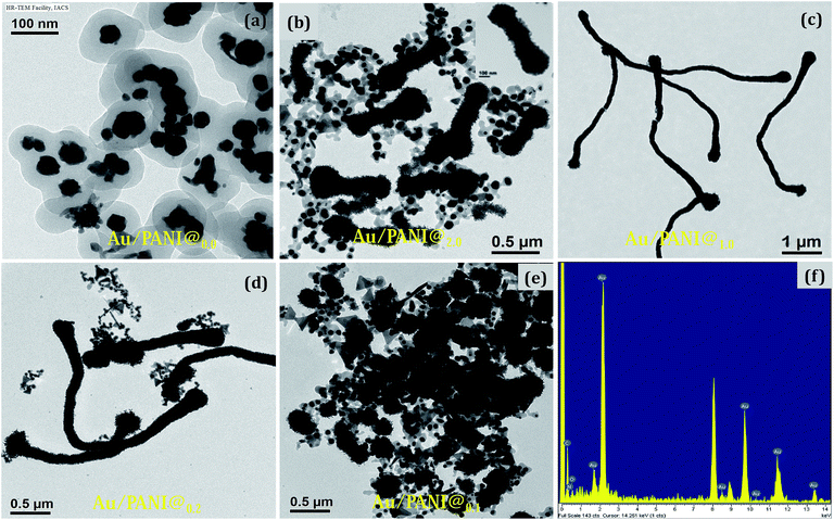
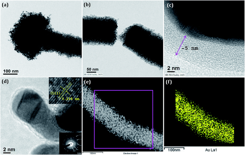
Nanostructures of Au/PANI were prepared with different molar ratio of HAuCl4 to aniline and were checked by FESEM observations (Fig. 1). Spherical morphology of Au/PANI@0.0 (in absence of CA) was clearly seen in Fig. 1a at equal molar ratio of HAuCl4 to aniline, whereas in the presence of CA and at the equal molar ratio of HAuCl4 to aniline, worm-like nanofiber morphology was observed. These important observations signified that there were tremendous effects of CA on the formation of Au/PANI nanostructures. It was also seen that the morphology of Au/PANI depended on the molar ratio of CA to aniline. Fibrous networks of Au/PANI were formed at the molar ratio of 1.0 and 0.20 (Fig. 1c and d) and spherical aggregates with irregular aggregates were observed at the molar ratio of 2.0 and 0.10 (Fig. 1b and e). Without CA, aniline was directly added to HAuCl4 aqueous solution at the identical reaction condition (Table S1†) where Au3+ oxidised aniline to PANI and itself was reduced to Au1+ ions that disproportionated to Au-nanoparticle and Au3+ ions (Scheme 1).23,24 HAuCl4 in the presence of CA starts to form the CA capped Au-nanoparticle (Fig. S1†). The surface of the Au-nano contains numerous –COOH groups that interact with aniline monomer to form anilinium ions, which were polymerised in the presence of Au3+ ions that originated from the disproportion reaction. To minimise surface energy, the PANI formed thus arranges one dimensionally to form worm-like nanofibers (Fig. 1c and 2c).Subsequent HRTEM images (Fig. 2) unanimously support the earlier observations made by FESEM results. Au/PANI nanofibers with uniform diameter of 100–110 nm and lengths of more than 5 μm were formed when the CA to aniline molar ratio was 1.0. The nanofibers were worm-like and growth of the fibers started from a spherical head (Fig. 3a). The aspect ratio of the nanofibers decreased by changing the molar ratio from 0.2 to 0.1 and finally small Au-nanoparticles covered with PANI layers were noticed. From the microscopic studies, we can infer that a 1![[thin space (1/6-em)]](https://www.rsc.org/images/entities/char_2009.gif) :
:![[thin space (1/6-em)]](https://www.rsc.org/images/entities/char_2009.gif) 1 molar ratio of CA to aniline was a required condition to prepare the high aspect ratio Au/PANI nanofibers. A typical high magnified image (Fig. 3b and c) showed that tiny shaped Au-nanoparticles were assembled together to form a high and uniformly dispersed Au-nanofibers, which were coated by a thin PANI layer. EDX studies from FESEM (Fig. 1f) and from HRTEM (Fig. 2f) indicated the presence of carbon, oxygen, nitrogen and a higher content of Au in the Au/PANI@1.00 nanofibers. By considering the contrast differences between Au-nanoparticle and coated PANI, the thickness of the PANI layer on Au was measured. It was found that in the absence of CA, the thickness of the PANI layer over Au-nanoparticles was ∼30 nm and in the presence of CA it was ∼5 nm. A dark field image (Fig. 3e) and mapping image (Fig. 3f) of the nanofibers cited the presence of dispersed Au-nanoparticles into Au/PANI nanostructures. Careful observation revealed that there are small Au nanorods (Fig. S4c†) present instead of spherical shaped Au-nanoparticles. The FFT image produced a lattice of 2.38 Å distance that was exactly matched with the (111)-plane of Au (Fig. 5) and a selected area electron diffraction (SAED) also confirmed the presence of another plane of Au.
1 molar ratio of CA to aniline was a required condition to prepare the high aspect ratio Au/PANI nanofibers. A typical high magnified image (Fig. 3b and c) showed that tiny shaped Au-nanoparticles were assembled together to form a high and uniformly dispersed Au-nanofibers, which were coated by a thin PANI layer. EDX studies from FESEM (Fig. 1f) and from HRTEM (Fig. 2f) indicated the presence of carbon, oxygen, nitrogen and a higher content of Au in the Au/PANI@1.00 nanofibers. By considering the contrast differences between Au-nanoparticle and coated PANI, the thickness of the PANI layer on Au was measured. It was found that in the absence of CA, the thickness of the PANI layer over Au-nanoparticles was ∼30 nm and in the presence of CA it was ∼5 nm. A dark field image (Fig. 3e) and mapping image (Fig. 3f) of the nanofibers cited the presence of dispersed Au-nanoparticles into Au/PANI nanostructures. Careful observation revealed that there are small Au nanorods (Fig. S4c†) present instead of spherical shaped Au-nanoparticles. The FFT image produced a lattice of 2.38 Å distance that was exactly matched with the (111)-plane of Au (Fig. 5) and a selected area electron diffraction (SAED) also confirmed the presence of another plane of Au.
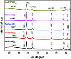 | ||
| Fig. 5 Powdered XRD pattern of Au/PANI@0.0, Au/PANI@2.0, Au/PANI@1.0, Au/PAN@0.2 and Au/PANI@0.1 composites. | ||
UV-vis study
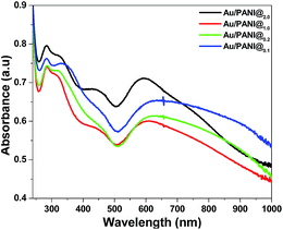
UV-vis spectra of Au/PANI composites (Fig. 4) have three absorption peaks centered at 284, 450, ∼600 and a broad peak ∼750 nm having extended tails in the NIR region. Three peaks are assigned to π–π* transitions of benzenoid ring, polaron–π* and the π–polaron transition of PANI, respectively.10,16 The surface plasmon resonance band of the Au nanoparticles appeared at ∼600 nm in the Au/PANI composites,25,26 whereas CA stabilized Au nanoparticles produces a band at 545 nm with spherical particles size ∼200 nm (Fig. S1†). Red shift (∼55 nm) of plasmon resonance band of Au in the Au/PANI composite primarily indicates the presence of small Au-nanorods (Fig. S4c†), already supported by HRTEM observation (Fig. 3d).25XRD study
The in situ synthesis of Au/PANI composites and the presence of Au in PANI matrix are further characterized by X-ray diffraction (XRD) study (Fig. 5). XRD patterns of Au/PANI composites show the presence of four well-known characteristic peaks of Au-nano at 38.2°, 44.3°, 64.7°, 77.7°, 81.8°, including a PANI peak at 25°. A broad peak centered at 25° is indicative of the amorphous nature of PANI. Five sharp peaks centred at 38.2°, 44.3°, 64.7°, 77.7° and 81.8° corresponds to the (111), (200), (220), (311) and (222) crystal planes of Au, indicating the presence of fcc Au in the Au/PANI composites.27,28,31XPS study
X-ray photoelectron spectroscopy (XPS) was used to study Au-NP formation (Fig. 6). The Au/PANI composite (Fig. 6a) shows XPS signals at ∼59, 85.6, 89.3, 110, 337.5, 355 and 547.5 eV, respectively, for Au (5p3/2, 4f7/2, 4f5/2, 5s, 4d5/2, 4d3/2 and 4p3/2), carbon (at 287.5 eV, 1s), nitrogen (at 502.5 eV, 1s) and oxygen (at 535 eV, 1s).29,30 The binding energies for the Au doublet are 85.6 eV (4f7/2) and 89.3 eV (4f5/2), peak to peak distance is ∼3.7 eV.31 The presence of Au 4f doublet (4f7/2 and 4f5/2) has confirmed that Au-nanoparticles are formed and present in the metallic (Au0) state. The absence of a 2p3/2 electron signal at 197–200 eV indicates that Au is present in the metallic state (Au0), and there is no possibility of the presence of AuCl4− (Au3+), AuCl2− (Au1+) in the Au/PANI composite.31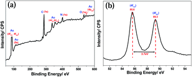 | ||
| Fig. 6 (a) X-ray photoelectron spectra for Au/PANI@1.0 composite synthesized by Scheme 1 and (b) represent Au0 4f doublet (4f7/2 and 4f5/2) of Au-nano produce in Scheme 1. | ||
FTIR study
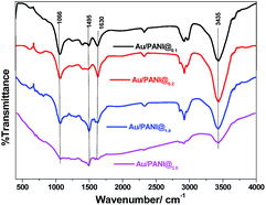
The Au/PANI composites were further characterized by FTIR spectroscopy (Fig. 7). FTIR spectra show characteristic bands of PANI at ∼3435 cm−1 (N–H stretching), 1630 cm−1 (attributed to the C![[double bond, length as m-dash]](https://www.rsc.org/images/entities/char_e001.gif) C stretching of the quinoid rings), 1480 cm−1 (C
C stretching of the quinoid rings), 1480 cm−1 (C![[double bond, length as m-dash]](https://www.rsc.org/images/entities/char_e001.gif) C stretching of benzenoid rings), 1306 cm−1 (C–N stretching mode), and 1143 cm−1 (N
C stretching of benzenoid rings), 1306 cm−1 (C–N stretching mode), and 1143 cm−1 (N![[double bond, length as m-dash]](https://www.rsc.org/images/entities/char_e001.gif) Q
Q![[double bond, length as m-dash]](https://www.rsc.org/images/entities/char_e001.gif) N, Q representing the quinoid ring).10,16
N, Q representing the quinoid ring).10,16
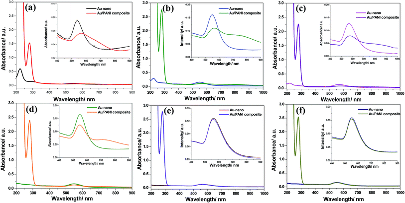
To further obtain insight into the mechanism of formation of nanofiber, a series of time dependent UV-vis experiments were performed with seed solution (CA to HAuCl4 molar ratio was 1.0). 1 mM aniline was added to the seed solution at different time intervals (1 h, 2 h, 3 h, 4 h, 5 h and 12 h) and spectra were recorded. In the absence of aniline (i.e. seed solution only), UV-vis spectra (Fig. 8) have two absorption bands at 220 nm for Au3+ species and 545 nm for surface plasmon resonance (SPR) peak of Au0. Subsequent HRTEM study showed the presence of CA stabilised Au-nanoparticles (Fig. S1a†). With time, the plasmon resonance peak is not shifted, but intensity enhances, indicating the gradual increase of Au0 in the solution. The intensity of the Au3+ peak (at 220 nm) decreases with time, and after 4 h, the peak of Au3+ vanishes (Fig. S5†), showing that the formation of Au-nanoparticles completes within 4 h. In other words, it indicates that the Au3+ ion, which is essential for the oxidation of aniline to PANI, is available for up to 4 h (Fig. 8a–d). In the presence of aniline and up to 4 h, the formation of PANI is taking place as it is evidenced from the presence of π–polaron transition of PANI at ∼750 nm as well as the SPR peak of Au0 at 575 nm. Significantly, it is shifted to higher wavelength with respect to the 545 nm peak in the seed solution. After 4 h (Fig. 8e and f), the peak of the π–polaron transition of PANI is absent, i.e., no polymerisation occurs after 4 h due to the absence of Au3+ ions in the solution (Fig. S5†). To achieve a nanofibre of higher aspect ratio, a seed solution (Au-60) was chosen. This is performed to eradicate the unwanted structures of Au (hexagonal, triangle, irregular Au-nanoparticle, Fig. S2a and S3b†).
Application of Au/PANI as hetero-catalysts for toxic aromatic nitro-compounds reduction
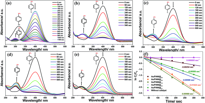
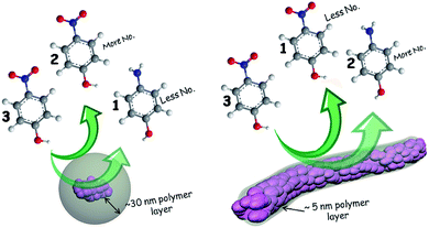
The catalytic reduction of toxic aromatic nitro-compounds to the corresponding amino-compound derivatives by NaBH4 in the presence of heterogeneous Au/PANI catalyst was selected as a model reaction to examine the catalytic activity as well as recyclability of Au/PANI composites.UV-vis spectra and the change of concentration of 4-nitrophenol compounds with time in the presence of different Au/PANI nanostructures as a heterogeneous catalyst and NaBH4 as a reducing agent is illustrated in Fig. 9. The absorption peak of 4-nitrophenol is centred at 317 nm, and after the addition of freshly prepared ice cold NaBH4 solution, the absorption peak is shifted to 400 nm. This indicates the formation of 4-nitrophenolate ions in the solution (Fig. S6†). The peak centred at 400 nm for 4-nitrophenolate ion is gradually decreased as the reduction proceeds in the presence of the catalyst (Au/PANI composites).6,22 With different Au/PANI nanostructures, the reaction rate depends upon the thickness of PANI layer on the Au-nanoparticles (Fig. 9f). In addition, the new absorption peak at 300 nm emerges and the intensity gradually increases owing to the formation of 4-aminophenol in the medium. Au/PANI@1.0 and Au/PANI@0.2 have excellent rate of the reduction compared to Au/PANI@0.0 nanostructures. This is possibly because of the thinner layer of PANI (∼5 nm) in Au/PANI@1.0 and Au/PANI@0.2 than that of Au/PANI@0.0 (∼30 nm).
A thinner coating of PANI over on Au-nano in Au/PANI@1.0 nanostructures facilitates the diffusion of nitrophenols that get easy contact to the Au-nano surface (Fig. 10), which enhances the rate of reduction.
Among the 5 different composites Au/PANI@1.0 has better catalytic activity compared to other composites towards 4-nitrophenol reduction. Reduction of three other aromatic nitro compounds, 2,4-dinitrophenol (2,4-DNP) and 2,4,6-trinitrophenol (2,4,6-TNP),32,33 has been also achieved by Au/PANI@1.0 as a catalyst and NaBH4 as a reducing agent (Fig. S7–S9†).
Conclusions
We successfully synthesized PANI coated Au-nano with spherical and worm-like morphology by changing the CA to aniline molar ratio. Polymer (PANI) layer thickness on Au-nanoparticles also varies with the presence and absence of CA. Intense morphological observation indicates that CA plays a critical role in the formation of worm-like Au/PANI nanostructures. The length of nanofiber also depends on the CA to aniline ratio. Prepared composites act as a catalyst for reduction of different aromatic nitrophenols. Catalytic activity varies according to the thickness of the PANI layer on Au-nano. The rate of reaction changes from 0.00254 s−1 to 0.00988 s−1 when PANI thickness changes from ∼30 nm to ∼5 nm.Acknowledgements
Dr Malik acknowledges CSIR, INDIA (Project no.: 02(0161)/13/EMR-II) for the financial support. S.M. and U.R. are indebted to CSIR, New Delhi, India, for their fellowship. The authors are thankful to the Unit of Nanoscience (DST, Govt. of India) at IACS for HRTEM and FESEM.References
- L. J. Lauhon, M. S. Gudiksen, D. Wang and C. M. Lieber, Nature, 2002, 420, 57 CrossRef CAS PubMed.
- A. Babel, D. Li, Y. Xia and S. A. Jenekhe, Macromolecules, 2005, 38, 4705 CrossRef CAS.
- (a) B. Hua, J. Motohisa, Y. Kobayashi, S. Hara and T. Fukui, Nano Lett., 2009, 9, 112 CrossRef CAS PubMed; (b) H. J. Choi, J. C. Johnson, R. He, S. K Lee, F. Kim, P. Pauzauskie, J. Goldberger, R. J. Saykally and P. Yang, J. Phys. Chem. B, 2003, 107, 8721 CrossRef CAS.
- (a) C. O. Baker, B. Shedd, R. J. Tseng, A. A. Martinez-Morales, C. S. Ozkan, M. Ozkan, Y. Yang and R. B. Kaner, ACS Nano, 2011, 5, 3469 CrossRef CAS PubMed; (b) R. J. Tseng, J. Huang, J. Ouyang, R. B. Kaner and Y. Yang, Nano Lett., 2005, 5, 1077 CrossRef CAS PubMed.
- (a) J. C. Scott, Science, 2004, 304, 62 CrossRef CAS PubMed; (b) J. Ouyang, C. W. Chu, C. R. Szmanda, L. Mal and Y. Yang, Nat. Mater., 2004, 3, 918 CrossRef CAS PubMed.
- (a) B. Baruah, G. J. Gabriel, M. J. Akbashev and M. E. Booher, Langmuir, 2013, 29, 4225 CrossRef CAS PubMed; (b) X. Z. Li, K. L. Wu, Y. Yea and X. W. Wei, Nanoscale, 2013, 5, 3648 RSC.
- (a) F. Lin and R. Doong, J. Phys. Chem. C, 2011, 115, 6591 CrossRef CAS; (b) Q. An, M. Yu, Y. Zhang, W. Ma, J. Guo and C. Wang, J. Phys. Chem. C, 2012, 116, 22432 CrossRef CAS.
- B. C. Sih and M. O. Wolf, Chem. Commun., 2005, 3375 RSC.
- (a) H. S. Kolla, S. P. Surwade, X. Zhang, A. G. MacDiarmid and S. K. Manohar, J. Am. Chem. Soc., 2005, 127, 16770 CrossRef CAS PubMed; (b) D. Li, J. Huang and R. B. Kaner, Acc. Chem. Res., 2009, 42, 135 CrossRef CAS PubMed; (c) E. Marie, R. Rothe, M. Antonietti and K. Landfester, Macromolecules, 2003, 36, 3967 CrossRef CAS.
- (a) U. Rana, K. Chakrabarti and S. Malik, J. Mater. Chem., 2012, 22, 15665 RSC; (b) U. Rana and S. Malik, Chem. Commun., 2012, 48, 10862 RSC.
- (a) S. Virji, R. B. Kaner and B. H. Weiller, Chem. Mater., 2005, 17, 1257 CrossRef; (b) S. Virji, J. Huang, R. B. Kaner and B. H. Weiller, Nano Lett., 2004, 4, 491 CrossRef CAS.
- (a) J. Chen, P. Xiao, J. Gu, D. Han, J. Zhang, A. Sun, W. Wang and T. Chen, Chem. Commun., 2014, 50, 1212 RSC; (b) Y. S. Bao, M. Baiyin, B. Agula, M. Jia and B. Zhaorigetu, J. Org. Chem., 2014, 79, 6715–6719 CrossRef CAS PubMed.
- M. C. Daniel and D. Astruc, Chem. Rev., 2004, 104, 293 CrossRef CAS PubMed.
- (a) B. L. V. Prasad, S. I. Stoeva, C. M. Sorensen, V. Zaikovski and K. J. Klabunde, J. Am. Chem. Soc., 2003, 125, 10488 CrossRef CAS PubMed; (b) Z. F. Zhang, H. Cui, C. Z. Lai and L. J. Liu, Anal. Chem., 2005, 77, 3324 CrossRef CAS PubMed.
- (a) H. Sun, Y. Luo, Y. Zhang, D. Li, Z. Yu, K. Li and Q. Meng, J. Phys. Chem. C, 2010, 114, 11673 CrossRef CAS; (b) D. W. Wang, F. Li, J. Zhao, W. Ren, Z. G. Chen, J. Tan, Z. S. Wu, I. Gentle, G. Q. Lu and H. M. Cheng, ACS Nano, 2009, 7, 1745 CrossRef PubMed.
- (a) U. Rana, K. Chakrabarti and S. Malik, J. Mater. Chem., 2011, 21, 11098 RSC; (b) U. Rana, S. Mondal, J. Sannigrahi, P. K. Sukul, M. A. Amin, S. Majumdar and S. Malik, J. Mater. Chem. C, 2014, 2, 3382 RSC.
- (a) Z. Wei, Z. Zhang and M. Wan, Langmuir, 2002, 18, 917 CrossRef CAS; (b) Y. Yang and M. Wan, J. Mater. Chem., 2002, 12, 897 RSC; (c) J. Huang, S. Virji, B. H. Weiller and R. B. Kaner, J. Am. Chem. Soc., 2003, 125, 314 CrossRef CAS PubMed.
- (a) T. Xue, X. Wang, S. K. Kwak and J. M. Lee, Ind. Eng. Chem. Res., 2013, 52, 5072 CrossRef CAS; (b) Z. Peng, L. Guo, Z. Zhang, B. Tesche, T. Wilke, D. Ogermann, S. Hu and K. Kleinermanns, Langmuir, 2006, 22, 10915 CrossRef CAS PubMed.
- J. M. Liua and S. C. Yang, Chem. Commun., 1991, 1529 RSC.
- (a) D. Li and R. B. Kaner, J. Mater. Chem., 2007, 17, 2279 RSC; (b) B. Zhao, S. Huang, R. Zhang, P. Xu and H. L. Wang, CrystEngComm, 2012, 14, 1542 RSC.
- D. Li and R. B. Kaner, J. Am. Chem. Soc., 2006, 128, 968 CrossRef CAS PubMed.
- S. Wunder, F. Polzer, Y. Lu, Y. Mei and M. Ballauff, J. Phys. Chem. C, 2010, 114, 8814 CAS.
- S. Kumar, K. S. Gandhi and R. Kumar, Ind. Eng. Chem. Res., 2007, 46, 3128 CrossRef CAS.
- C. H. Gammons, Y. Yu and A. E. Williams-Jones, Geochim. Cosmochim. Acta, 1997, 61, 1971 CrossRef CAS.
- (a) S. E. Lohse, J. R. Eller, S. T. Sivapalan, M. R. Plews and C. J. Murphy, ACS Nano, 2013, 7, 4135 CrossRef CAS PubMed; (b) A. F. Zedan, S. Moussa, J. Terner, G. Atkinson and M. S. El-Shall, ACS Nano, 2013, 7, 627 CrossRef CAS PubMed; (c) E. Hutter, S. Boridy, S. Labrecque, M. L. Hebert, J. Kriz, F. M. Winnik and D. Maysinger, ACS Nano, 2010, 4, 2595 CrossRef CAS PubMed; (d) T. K. Sau and C. J. Murphy, J. Am. Chem. Soc., 2004, 126, 8648 CrossRef CAS PubMed; (e) N. R. Jana, L. Gearheart and C. J. Murphy, J. Phys. Chem. B, 2001, 105, 4065 CrossRef CAS.
- (a) I. O. Jimenez, X. Lopez, J. Arbiol and V. Puntes, ACS Nano, 2012, 6, 2253 CrossRef PubMed; (b) K. Huang, H. Ma, J. Liu, S. Huo, A. Kumar, T. Wei, X. Zhang, S. Jin, Y. Gan, P. C. Wang, S. He, X. Zhang and X. J. Liang, ACS Nano, 2012, 6, 4483 CrossRef CAS PubMed; (c) C. J. Murphy, T. K. Sau, A. M. Gole, C. J. Orendorff, J. Gao, L. Gou, S. E. Hunyadi and T. Li, J. Phys. Chem. B, 2005, 109, 13857 CrossRef CAS PubMed; (d) J. Gao, C. M. Bender and C. J. Murphy, Langmuir, 2003, 19, 9065 CrossRef CAS; (e) B. D. Busbee, S. O. Obare and C. J. Murphy, Adv. Mater., 2003, 15, 414 CrossRef CAS.
- T. Zhang, W. Wang, D. Zhang, X. Zhang, Y. Ma, Y. Zhou and L. Qi, Adv. Funct. Mater., 2010, 20, 1152 CrossRef CAS.
- K. Huang, Y. Zhang, Y. Long, J. Yuan, D. Han, Z. Wang, L. Niu and Z. Chen, Chem.–Eur. J., 2006, 12, 5314 CrossRef CAS PubMed.
- (a) A. Kumar, S. Mandal, P. R. Selvakannan, R. Pasricha, A. B. Mandale and M. Sastry, Langmuir, 2003, 19, 6277 CrossRef CAS; (b) C. Jin, T. C. Nagaiah, W. Xia, B. Spliethoff, S. Wang, M. Bron, W. Schuhmann and M. Muhler, Nanoscale, 2010, 2, 981 RSC.
- (a) W. Luo, C. Zhu, S. Su, D. Li, Y. He, Q. Huang and C. Fan, ACS Nano, 2010, 4, 7451 CrossRef CAS PubMed; (b) X. R. Li, X. L. Li, M. C. Xu, J. J. Xu and H. Y. Chen, J. Mater. Chem. A, 2014, 2, 1697 RSC.
- D. V. Leff, L. Brandt and J. R. Heath, Langmuir, 1996, 12, 4723 CrossRef CAS.
- B. Xu, X. Wu, H. Li, H. Tong and L. Wang, Macromolecules, 2011, 44, 5089 CrossRef CAS.
- M. Megharaj, H. W. Pearson and K. Venkateswarlu, Arch. Environ. Contam. Toxicol., 1991, 21, 578 CrossRef CAS.
Footnote |
| † Electronic supplementary information (ESI) available: Preparation of Au/PANI composite (Table 1), TEM image and UV-vis spectra of synthesized Au-60 seed solution and Au-240 seed solution, synthesis of Au/PANI composite from different Au seed solution. Aspect ratio of a single Au-nano formation kinetics, UV-vis spectra of 4-NP reduction by NaBH4 without catalyst, UV-vis spectra and rate calculation of 4-NA, 2,4-DNP and 2,4,6-TNP reduction. See DOI: 10.1039/c4ra12080a |
| This journal is © The Royal Society of Chemistry 2014 |

