
A tensiometric study of magnetorheological suspensions' stability
M. Sedlacik* and
V. Pavlinek
Centre of Polymer Systems, University Institute, Tomas Bata University in Zlin, Nad Ovcirnou 3685, 760 01, Zlin, Czech Republic. E-mail: msedlacik@ft.utb.cz; Fax: +420 57 603 1444; Tel: +420 57 603 8027
First published on 30th October 2014
Abstract
A thin (3-aminopropyl)triethoxysilane (3APTS) layer with a grafting density around 50 groups per nm2 was coated onto soft magnetic carbonyl iron (CI) particles. Their physical characteristics were examined using various methods, and the results revealed that the coating layer did not affect the particles' morphology and magnetic properties while their resistance against thermal oxidation and chemical degradation was considerably improved. This study further evaluates the surface free energy of the particles under investigation using tensiometry, namely capillary rise experimental methods based on the Washburn theory. The dispersive and polar components of surface free energy were subsequently computed through the application of the Owens–Wendt–Rabel–Kaeble theory. It was observed that the coating of CI particles with 3APTS increased the dispersive component of surface free energy, resulting in the improved compatibility of such particles with non-polar silicone oil which is used as a carrier liquid for magnetorheological (MR) suspensions. Furthermore, the 3APTS coating has a negligible influence on MR properties in comparison with an uncoated CI particle-based MR suspension, as was proved by steady shear and small-strain oscillatory shear tests under various external magnetic fields. The improved compatibility of 3APTS-coated CI particles with silicone oil was reflected in the better sedimentation stability of the MR suspension, observed via tensiometry for the first time for MR suspensions, in comparison with the uncoated CI particle-based suspension.
Introduction
Magnetorheological (MR) suspensions, smart materials capable of the rapid and reversible tuning of their rheological properties via an applied external magnetic field,1,2 represent outstanding materials for intelligent systems finding real applications in the variable control of applied damping/force adjustment devices.3,4 Nonetheless, several obstacles exist, such as the sedimentation of magnetic particles within the MR suspension due to an imbalance between the high density of the magnetic agents and the relatively low density of the carrier liquid,5 the poor redispersibility of settled particles out of the MR suspension,6 the poor durability of MR performance,7 or the weak chemical degradation resistance of magnetic particles,8 all of which can cause serious problems when MR suspensions are utilized in engineering devices. To overcome these crucial limitations partially or completely, different methods including passivation layers on magnetic particle formation,9,10 the use of viscoplastic media,11 adding special types of additives12 or surfactants,13 or the use of non-spherical particle-based14 or bidispersed15 MR suspensions have been widely introduced. The coating of magnetic particles with an appropriate surface layer seems to be one of the most efficient variants since it not only decreases particle density and improves durability and chemical resistance but also positively affects the surface free energy of magnetic particles, which consequently improves their mutual compatibility with the carrier liquid.16In the development of novel MR suspensions with improved operation features, attention is nowadays focused mainly on the sampling of particles, grading, particle shape, porosity or density. Beyond these classical analyses, the wettability of magnetic particles with a carrier liquid, frequently represented by various oils, is at least as important a property as the above mentioned. However, the wettability and surface free energy of magnetic particles used in MR suspension have been, according to our best knowledge, studied only rarely.16,17 The quantity describing a solid's wetting by a liquid is called contact angle, θ, and is defined geometrically as the angle formed by a liquid drop on the solid matrix at the three-phase solid/liquid/gas boundary.18 Generally, a direct θ measurement is a standard experimental method for planar solid surfaces or fibres. Nevertheless, the direct approach cannot be used on finely-dispersed solid materials since the approach is critical in terms of precision, reproducibility, and absolute values obtained at least due to the capillary forces existing in a powder material or the irregular surface of the compressed pellets usually used for simplicity. A reliable experimental measurement of a solid particle's θ is the capillary rise technique based on Washburn's theory of the liquid penetration in porous media leading to a significant improvement of thermodynamic characterization of a solid particle's surface.19
Surface free energy, also referred to as surface tension, is a value describing the interaction of the condensed phase surface, i.e., solid or liquid, with its surroundings. Surface free energy, a criterion of which is the ability of the material to be coated, can be improved via surface modification by, e.g., plasma treatment,10 and evaluated via the changes of θ with respect to the intended material's use. Various approaches have been developed to calculate the surface free energy of powder from θ measurements.20–22
Nanostructured (3-aminopropyl) triethoxysilane (3APTS) grafted onto the carbonyl iron (CI) magnetic particles was used in this study since siloxane-based polymer coatings showed super-hydrophobic particle characteristics resulting in the increased dispersion stability of the magnetic particles in the oil-based MR suspensions as well as protection from chemical or thermal oxidation.9,23 Furthermore, a tensiometry evaluation of θ enabling the subsequent particles' surface free energy calculation as well as a determination of their sedimentation characteristics, was used for MR suspensions for the first time.
Experimental
Reagents
For a model particle-suspended system, CI (HQ grade, BASF, Germany) and 3APTS were selected as a core and coating, respectively. The main material characteristics of bare CI are the spherical shape of the particles with d50 = 2 μm and the content of α-iron >97.8%. Commercial 3APTS of reagent grade (≥98%, purchased from Sigma-Aldrich, USA) was used for the CI particle coating.Coating of CI particles by 3APTS
Prior to coating with 3APTS, the surface of the CI particles (100 g) was first cleaned of any contamination and activated using 0.5 M HCl (100 mL, Penta Chemicals, Czech Republic). After that, to accelerate particle sedimentation during particle decanting with distilled water (5 times, 300 mL each), ethanol (2 times, 100 mL each) and finally acetone (2 times, 150 mL each), a magnet was placed under the bottom of the beaker. The residual acetone was evacuated at a pressure of 200 mbar at 60 °C for 2 hours.The next step in the coating is the functionalization of the activated CI particle surface, having more active sites after the activation with HCl enabling the grafting of higher amounts of 3APTS polymers. Briefly, 25 g of activated CI particles were dispersed in 100 mL of a non-polar solvent, toluene (p.a., Penta, Czech Republic), into a three-neck 250 mL flask fitted with a mechanical stirrer and a reflux condenser. The amount of 3APTS was calculated from the desired grafting density of 50 groups per nm2. The entire assembly was placed into a heating mantle and stirred for 8 hours at 110 °C. The intensity of agitation was 250 rpm. The coated CI particles were then separated from the toluene by sedimentation accelerated again with a magnet, washed with toluene (2 times, 200 mL each), ethanol (2 times, 200 mL each), and acetone (2 times, 200 mL each), and dried at a pressure of 200 mbar at 60 °C for 6 hours. It is worth noting that covalently-grafted 3APTS on the CI particles can further serve as a coupling agent through functional groups (–NH2). However, this will be the subject of a future study.
Characterization of particles
The surface characteristics of CI particles and their 3APTS-coated analogues were observed with scanning electron microscopy (SEM, VEGA II LMU, Tescan, Czech Republic) operated at 10 kV.Specific surface areas of particles under investigation were obtained by a volumetric gas adsorption method with advanced free space measurement in a BELLSORP-mini II (BEL Japan, Inc., Japan). The carrier gas in this device is helium, and adsorption experiments were further performed with nitrogen. The sample mass was 1.4 g.
A Fourier transform infrared spectroscopy (FTIR, Thermo Scientific, USA) was performed to verify the successful coating of the CI particles with 3APTS. The FTIR spectra were recorded using the attenuated total reflectance (ATR) technique with Germanium crystal in a range of 600–4000 cm−1 at 64 scans per spectrum at a 2 cm−1 resolution.
The magnetic properties (first magnetization curve and hysteresis cycle) of the microspheres were examined using a vibration sample magnetometry (VSM, EG&G PARC 704, Lake Shore, USA) at room temperature.
In order to examine resistance to thermal oxidation, a thermogravimetric analysis (TGA; TA Instruments Q500, USA) under an air atmosphere at a heating rate of 5 °C min−1 was made. To observe resistance to corrosion by acids, the same amounts of uncoated and 3APTS-coated CI particles were dispersed in a hydrochloric acid solution of concentration 0.05 mol L−1, and the pH values of the solutions as a function of time were recorded. Before the measurement, the pH-meter (Greisinger electronic, GPRT 1400, AN, Germany) was calibrated with two standard buffer solutions. After each measurement the probe of the pH-meter was rinsed with distilled water to remove any traces of the measured solution. Then the remaining water was removed with a scientific wipe because the remaining water could dilute the following measured sample. All measurements were performed at room temperature.
Surface free energy determination
In order to estimate the different contributions to the total energy of interactions between CI particles or their 3APTS-modified analogues and silicone oil used as a carrier liquid for MR suspensions, their surface free energy was determined by measuring the capillary velocities of particles in a specific cell as a function of the polarity of two testing liquids (water and diiodomethane, Sigma Aldrich, USA) of known surface tension components (Table 1) using a tensiometer Krűss K100 (KRŰSS GmbH, Germany). This method, following Washburn eqn (1), enables the calculation of θ for a specific pair of solid, which is in the form of powder, and liquid.
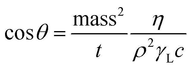 | (1) |
| Liquid | η [mPas] | ρ [g cm−3] | γDL [mN m−1] | γPL [mN m−1] |
|---|---|---|---|---|
| a Values adopted from the tensiometer Krűss K100 software LabDesk 3.2.2. | ||||
| Water | 1.002 | 0.998 | 19.9 | 52.2 |
| Diiodomethane | 2.762 | 3.325 | 48.5 | 2.3 |
| n-Hexane | 0.326 | 0.661 | 18.4 | 0.0 |
The total surface free energy, γ, of a given entity is created by different types of interactions. However, for simplification, γ may be expressed as the sum of only two terms:25 a dispersive component (superscript D) including van der Waals interactions, and a polar component (superscript P) including non-dispersive forces such as Debye or hydrogen-bond interactions:
| γ = γD + γP | (2) |
The surface energy of a solid, γS, can be further determined indirectly from the contact angle data using the equation of geometric mean developed and named by Owens–Wendt–Rabel–Kaeble (OWRK):21
 | (3) |
| y = mx + b | (4) |
 | (5) |
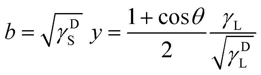 | (6) |
If the γL, γDL, and γPL values are known for the two testing liquids used for the tensiometric θ measurements, the values of x and y can be determined. Then, the squares of linear correlation from the plot of y versus x gives the polar (γPS) and dispersive (γDS) components of the total surface free energy of the studied powder material.
The capillary rise experiments were run by measuring the rate at which the testing liquid rises through the packed particles in a glass tube (Fig. 1). Before measurement, 3.5 g of tested particles for all measurements was placed into a cylindrical glass tube with an inner diameter of about 8 mm, which has been previously cleaned according to a specific procedure. The packing density as a key factor for reproducibility was appropriately controlled. The glass tube with the sample inside was attached to the electronic balance of the tensiometer, and a container with the testing liquid was raised with a controlled speed of 7 mm min−1. At the instant of contact, i.e., a force increase was observed, a spontaneous adsorption of the testing liquid started. The uniform rise of the liquid through the packed particles caused a weight increase over related time. After the experiment, a θ value was obtained using a linear regression, according to the least square method, to the initial adsorption in the recorded mass2/t curve. All capillary rise measurements were performed at 25 °C.
 | ||
| Fig. 1 Schematic view of the measuring system for capillary rise measurement. | ||
Preparation and characterization of MR suspensions
Two MR suspensions with the same particle concentration (10 vol%) in silicone oil (Lukosiol M 200, viscosity ηc = 194 mPa s, density ρc = 0.970 g cm−3, Chemical Works Kolín, Czech Republic) were prepared. The first one contained 10 vol% of uncoated CI particles while the second consisted of their 3APTS-coated analogue. The tested MR suspensions were prepared by a thorough mixing of the CI particles in silicone oil, with the intention of creating a well-dispersed system for measurement, i.e., both suspensions formed well-dispersed systems for the period of the experiment.The MR characteristics of the suspensions under investigation in steady shear and oscillatory shear flow were determined using a Physica MCR 502 rotational rheometer (Anton Paar GmbH, Austria) with the Physica MRD 170/1 T magneto-cell at 25 °C. True magnetic flux density (not the one indicated by software calculations only) was measured using a Hall probe (FH 51, MAGNET-PHYSIK Dr Steingroever GmbH, Germany). A parallel-plate measuring system with a diameter of 20 mm and gap of 0.5 mm was used.
The steady shear experiments were performed using both controlled shear rate and controlled shear stress modes to obtain dynamic and static yield stresses, respectively. In the case of the controlled shear rate mode, the shear rate range was from 0.1 to 200 s−1 in a logarithmic scale with 6 pts per decade. The range of shear stresses applied during controlled shear stress experiments was set according to the applied magnetic field intensity and thus rigidity of the formed structures.
The small-strain oscillatory experiments were carried out through strain sweeps and frequency sweeps. The linear viscoelasticity (LVE) region was found through storage, G′, and loss, G′′, moduli measurements as a function of strain, γ. The used strain range was from 10−3% to 101% at a fixed frequency 6.28 rad s−1. After finding the limits of the LVE region, the frequency sweeps were measured in the range of frequencies from 0.628 to 62.8 rad s−1 at a constant amplitude strain (obtained from the LVE investigation).
The resulting flow responses were examined as a function of the magnetic field intensity ranging from 0 to 87 kA m−1 in both rheological modes. During each run under a magnetic field, the MR suspension was first sheared (![[small gamma, Greek, dot above]](https://www.rsc.org/images/entities/i_char_e0a2.gif) = 50 s−1) at a zero field for 60 s to mix the particles randomly. After the measurement, the system was completely demagnetized.
= 50 s−1) at a zero field for 60 s to mix the particles randomly. After the measurement, the system was completely demagnetized.
Sedimentation measurements of 1 vol% MR suspensions of uncoated CI particles and their 3APTS-coated analogues in silicone oil were investigated using the tensiometer Krűss K100, i.e., with the same device used for the surface free energy evaluation. The principle of the sedimentation measurement is as follows. A crater-shaped measuring probe was attached to a balance and moved to the surface of the suspension (7 mm min−1 in our case). After the contact of the probe with the surface is detected, the probe is further immersed with controlled speed (50 mm min−1 in our case) into the homogenously-dispersed (proper mixing and sonication for 2 min) MR suspension to a given immersion depth (15 mm in our case). The measuring probe catches the sinking magnetic particles and records their weight as a function of time, which allows the sedimentation speed to be calculated.
Results and discussion
Microstructure of particles
Fig. 2 shows the size and surface morphology of both uncoated CI particles and their 3APTS-coated analogues observed via SEM. The average size of the 3APTS-coated CI particles was slightly larger than that of uncoated ones as a result of the coating layer not exceeding 0.2 μm. The coated particles nevertheless kept their spherical shape, which confirms the uniform and complete coating with only some defects probably due to the low grafting density of 3APTS used. However, higher grafting density would undesirably influence the magnetic properties. | ||
| Fig. 2 (a) SEM images of uncoated CI particles. (b) SEM images of 3APTS-coated CI particles. | ||
Surface characterization of prepared particles
To confirm the successful coating of the magnetic particles with a polysiloxane-based polymer, FTIR spectra of 3APTS, uncoated CI particles and their 3APTS-coated analogues were analyzed (Fig. 3). As can be seen from the FTIR spectrum of uncoated CI particles (Fig. 3a), because of their composition consisting of more than 97.8% of iron, no characteristic bands are presented. Only one broad peak in the middle of the measured wavenumbers range is visible, probably due to the presence of an unknown residue. On the other hand, characteristic vibration peaks corresponding to the O–Si at 1072 cm−1, C–O at 1165 cm−1 and Si–CH2 at 1285 cm−1 (Fig. 3c) are matching with the structure of 3APTS.26 Another characteristic band for this polymer at 1441 cm−1 is corresponding to C–N, and that at 1388 cm−1 is attributed to the C–H aliphatic group. In addition, its polymeric structure is confirmed by the presence of alkyl groups, i.e., C–H vibrations in the 2800–3000 cm−1 region. Although the characteristic peaks are a little higher, probably due to the presence of CI particles, for 3APTS-coated CI particles (Fig. 3c) in comparison with pure 3APTS polymer, all the characteristic peaks are presented in this spectrum, confirming the successful formation of a polymeric layer onto the surface of the magnetic particles.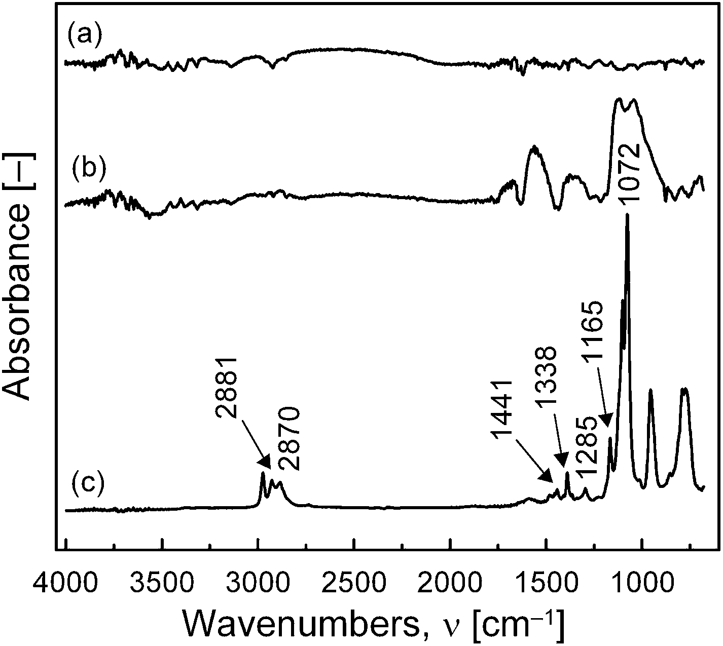 | ||
| Fig. 3 FTIR spectra of uncoated CI particles (a), their 3APTS-coated analogues (b), and 3APTS polymer (c). | ||
The specific surface area of uncoated CI particles is 1.06 m2 g−1, while the one for 3APTS-coated particles is only 0.89 m2 g−1, which, considering the similar particles size, points to an efficient particle coating. Such characterizations confirm the sufficient coating of CI particles, which must reflect changes in physical and chemical properties. Thus, the influence of coating on the particles' surface free energy resulting in changed sedimentation stability and on their MR performance will be examined further.
Capillary rise experiments with the Washburn method for a determination of contact angles have been used to evaluate the surface free energy of uncoated CI particles as well as their 3APTS-coated analogues. First of all, a geometric factor, c, (eqn (1)) was obtained using the capillary rise of a total wetting n-hexane (Sigma-Aldrich, USA) for both types of particles. The experiments were performed three times for each particle type under investigation, and the c factor was (2.66 ± 0.15) × 10−6 and (2.93 ± 0.10) × 10−6 for uncoated CI particles and their 3APTS-coated analogues, respectively. These values are very similar, reflecting the similar particle size. In Fig. 4, the dynamic liquid adsorption process for two testing liquids can be observed. As can be seen, the liquid adsorption of particles under investigation is obviously influenced by the polarity of the testing liquids because both particle types adsorbed more of the non-polar testing liquid, i.e., diiodomethane. This suggests that the liquid adsorption is strongly influenced by the Liftshitz–van der Waals interactions27 and, thus, the dispersive part of surface free energy will be predominant during particle wetting.
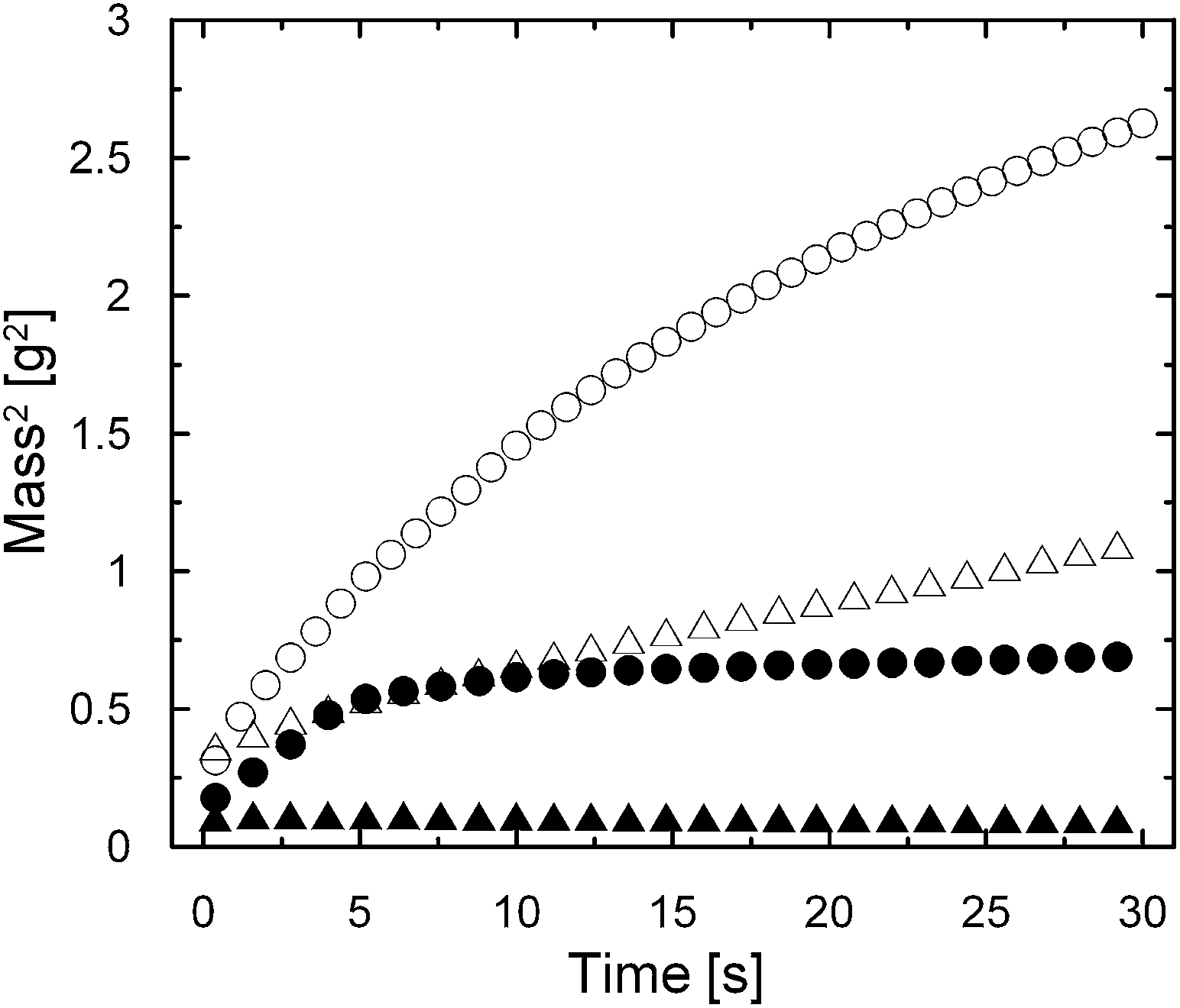 | ||
| Fig. 4 Sorption velocities of uncoated CI particles (spheres) and their 3APTS-coated analogues (triangles) measured during water (solid symbols) and diiodomethane (open symbols) adsorption. | ||
The θ values define the wetting behavior of the measured particles (Table 2). Already the θ values suggest a difference between uncoated magnetic particles of CI and their polymer-coated analogues. The θ values have been applied to the OWRK theory (eqn (3)), and the resulting surface free energy and its components for particles under investigation are summarized in Table 2.
| Particles | Contact angle [°] | γ [mN m−1] | γPS [mN m−1] | γDS [mN m−1] | |
|---|---|---|---|---|---|
| H2O | CH2I2 | ||||
| Uncoated CI | 81.8 | 62.6 | 23.6 | 15.4 | 8.2 |
| 3APTS-coated CI | 90.8 | 65.9 | 26.1 | 4.1 | 22.1 |
Although the total surface free energy was not significantly changed after the coating of CI particles with 3APTS, the particular components of surface free energy were reciprocally changed. The dispersive component became dominant after the coating, resulting in the better wetting of particles with non-polar liquids, among which the silicone oil used as a carrier liquid in MR suspensions belongs. The obtained results are in good accordance with trends observed after magnetic particle coating with a polymeric material by other groups,16 which makes tensiometry a powerful tool for investigation of MR suspension stability.
Surface characterization
Magnetic particles with a polymeric coating generally exhibit worse magnetic properties due to the non-magnetic character of the polymer surface layer. Thus, it is of essential interest to prepare a polymeric coating improving the properties of magnetic particles, such as their resistance against thermal oxidation or a better dispersion into the carrier liquid while having only a minimal effect on their magnetic properties. Thus, Fig. 5 shows the hysteresis cycles of uncoated CI particles and their 3APTS-coated analogues. A soft magnetic behavior is presented by both types of particles since their increasing and decreasing branches of the hysteresis cycles are hardly distinguishable. The shape of the hysteresis cycle of 3APTS-coated CI particles is comparable with the uncoated CI particles in its initial magnetic permeability, and only a small decrease in magnetization in the field of 10![[thin space (1/6-em)]](https://www.rsc.org/images/entities/char_2009.gif) 000 Oe can be observed; i.e., 174 emu g−1 and 159 emu g−1 for uncoated CI particles and their 3APTS-coated analogues, respectively. Hence, there is no significant influence of the polymeric coating on the magnetic properties, and an MR suspension based on 3APTS-coated CI particles would exhibit a similar MR performance as an uncoated CI-based MR suspension.
000 Oe can be observed; i.e., 174 emu g−1 and 159 emu g−1 for uncoated CI particles and their 3APTS-coated analogues, respectively. Hence, there is no significant influence of the polymeric coating on the magnetic properties, and an MR suspension based on 3APTS-coated CI particles would exhibit a similar MR performance as an uncoated CI-based MR suspension.
 | ||
| Fig. 5 VSM results of uncoated CI particles (spheres) and their 3APTS-coated analogues (triangles). | ||
Benefits of a polymeric surface layer
The 3APTS coating onto CI particles improves the thermal oxidation stability investigated via a thermo-gravimetric analysis in air atmosphere (Fig. 6). The weight of the uncoated CI particles begins to sharply increase above 200 °C due to the progressive oxidation of iron into FeO, Fe3O4 and finally Fe2O3. On the other hand, 3APTS-coated CI particles first show a postponed and much lower weight increase until a temperature around 400 °C, indicating the protection of the polymeric surface layer of the CI particles against thermal oxidation. A rapid oxidation of these particles occurs above 400 °C, implying a decomposition of the 3APTS layer.9,23 | ||
| Fig. 6 TGA curves of uncoated CI particles (solid line) and their 3APTS-coated analogues (dashed line). | ||
Another important factor for the efficient utilization of these smart systems in real applications is the anti-acid-corrosion resistance of magnetic particles used in MR suspensions, since the corrosion of particles over time leads to the formation of less-magnetic products, resulting in the decreased MR performance of the whole device. As can be observed in Fig. 7, the 3APTS-coating makes CI particles more resistant in acidic conditions represented by 0.05 M HCl. It is evident that 3APTS-coated particles are totally resistant for at least 20 minutes of the experiment. A small increase in pH (around 0.7) caused by the reduction of HCl appears thereafter, probably due to some defects present in the coating (observed also in Fig. 2); thus, the easier diffusion of protons through the polymeric shell takes place. On the other hand, the pH development is more pronounced in the case of uncoated CI particles, since the aqueous solution of HCl causes oxidation of the iron according to the equation:
| Fe + 2HCl + 6H2O → [Fe(H2O)6]Cl2 + H2 | (7) |
 | ||
| Fig. 7 Resistance of uncoated CI particles (spheres) and their 3APTS-coated analogues (triangles) against acidic conditions represented by 0.05 m HCl. | ||
Steady shear and yield stress
According to the almost identical character of the magnetization curves (Fig. 5) for uncoated CI particles and their 3APTS-coated analogues in the range of magnetic fields employed in most applications, i.e., 200 kA m−1 corresponding to 2500 Oe, MR suspensions based on both types of particles should exhibit similar MR performances from a magnetic properties point of view. However, the changed surface free energy could affect the particles' compatibility with silicone oil. Thus, flow properties representing dependence of shear stress on shear rate for 10 vol% MR suspensions based on uncoated CI particles and their 3APTS-coated analogues in silicone oil under various magnetic field intensities H are shown in Fig. 8. The slightly pseudoplastic behavior in the absence of a magnetic field at low shear rates for a 3APTS-coated CI particles-based MR suspension can be attributed to interaction forces between siloxanes bonded on CI particles and silicone oil. In the presence of a magnetic field, both systems exhibit Bingham plastic behavior showing that the magnetic particles were aligned into a chain-like structure sufficiently rigid to withstand certain deforming stresses without any external manifestation of flow. Moreover, a further increase in H induces higher dipole moments and the particular microstructures become stiffer. The rheological behavior of uncoated CI particles and their 3APTS-coated analogues is very similar since their magnetic susceptibility (Fig. 5) is also similar in the range of applied H. This evidence confirms that successful particle coating does not reduce MR performance while the thermal (Fig. 6) and chemical (Fig. 7) resistances of the particles are improved. | ||
| Fig. 8 Shear stress, τ, versus shear rate, for uncoated CI particles' (open symbols) and their 3APTS-coated analogues' (solid symbols) MR suspensions (10 vol%) in silicone oil in various magnetic field intensities at 25 °C. the symbols for the magnetic field intensities (kA m−1): 0 (spheres), 22 (triangles), 45 (squares), and 87 (reverse triangles). | ||
In Table 3, the static, τS, and dynamic, τD, (taken as a value of the shear stress at = 0.01 s−1) yield stresses are compared for 3APTS-coated CI particle-based MR suspensions at various magnetic field intensities since each of them has a different rheological nature and thus also characterizes the formed structure from a different viewpoint. The τS is related to the amount of stress necessary to get the structured material to flow from a resting position, i.e. it is an indication of the transformation from a solid state to a viscoplastic state. On the other hand, τD is understood as the stress necessary to stop the flow of the material, i.e., it is an indication of the transformation from the viscoplastic state back to the solid state.1 The τD is strongly influenced by the competition between hydrodynamic and magnetostatic forces in MR suspensions, and thus τS is more related to the induced stiffness of the formed internal structure after the application of the magnetic field. The results in Table 3 confirm this fact and correlate well with theoretical predictions stating that τS values are higher than τD values.1
= 0.01 s−1) yield stresses for MR suspension (10 vol%) based on 3APTS-coated CI particles as a function of magnetic field intensity
| H [kA m−1] | τS [Pa] | τD [Pa] |
|---|---|---|
| 22 | 61 | 56 |
| 45 | 196 | 162 |
| 87 | 363 | 368 |
Viscoelastic properties
Oscillatory shear tests represent an effective way to study the dynamic characteristics of microstructures formed in MR suspensions. Fig. 9 shows the storage modulus G′ representing the elastic behavior of the system, and the loss modulus G′′ representing the viscous behavior of the system, versus the angular frequency for a 3APTS-coated particle-based MR suspension. | ||
| Fig. 9 Storage, G′, (solid symbols) and loss, G′′, (open symbols) moduli versus angular frequency, ω, for 3APTS-coated CI particles based MR suspension (10 vol%) under various magnetic field intensities. The symbols for the magnetic field intensities (kA m−1): 0 (spheres), 22 (triangles), 45 (squares), and 87 (reverse triangles). | ||
In the absence of a magnetic field, G′′ is slightly larger than G′ almost throughout the angular frequency range (ω = 0.628–62.8 rad s−1 in our case), which confirms the appropriate fluidity of the MR suspension in a field-off state. Upon application of the external magnetic field, both G′ and G′′ increase in three and two orders of magnitude, respectively. In addition, G′ values are either constant or increase slightly as the angular frequency rises up to 62.8 rad s−1, which is evidence of a developed stiff three-dimensional network enabling the transmission of elastic forces within the MR system in the presence of a magnetic field.
Sedimentation test
The sedimentation stability was examined for both MR suspensions under investigation via tensiometry and is represented by the weight gain corresponding to the settling particles as a function of observation time (Fig. 10). The stability of 3APTS-coated CI particles is obviously higher compared to uncoated CI particles, which is probably caused by a higher dispersive component of surface free energy for 3APTS-coated CI particles (Table 2) resulting in their better wetting with a non-polar silicone oil used as a carrier liquid. The amount of 3APTS-coated CI particles sunk into a crater-shaped probe represent approximately only one half of the uncoated CI particles after 15 minutes of the test. | ||
| Fig. 10 Sedimentation course of MR suspensions (1 vol%) based on uncoated CI particles (solid line) and their 3APTS-coated analogues (dashed line). | ||
Conclusions
In this work, the possibility of CI particle passivation via a thin 3APTS surface layer against thermal oxidation and chemical degradation has been shown. Although the existence of 3APTS onto a CI particle surface was proved via FTIR, the morphology, specific surface areas and magnetic properties of particles investigated via SEM, BET, and VSM, respectively, have not been negatively affected. Only a small difference in total surface free energy was observed. However, the redistribution of dispersive and polar components of surface free energy occurred after particle coating as was confirmed after a contact angle evaluation consisting of capillary rise experiments of well-defined testing liquids followed by the application of the Owens–Wendt–Rabel–Kaeble theory. The dispersive components became dominant for 3APTS-coated CI particles, which resulted in their better wetting with a non-polar silicone oil used as a carrier liquid for MR suspensions. This evidence was confirmed by the improved sedimentation stability of MR suspension based on 3APTS-coated particles in comparison with an uncoated CI particle-based one. Finally, since the coating did not decrease the magnetic properties such as magnetic susceptibility and magnetization saturation, the 3APTS-coated particle-based MR suspension exhibited almost the same MR performance as its uncoated analogue.Acknowledgements
The author M. S. would like to thank the Grant Agency of the Czech Republic (14-32114P) for financial support. This article was written with support of the Operational Program Research and Development for Innovations co-funded by the European Regional Development Fund (ERDF) and the national budget of the Czech Republic, within the framework of the project Centre of Polymer Systems (reg. number: CZ.1.05/2.1.00/03.0111).Notes and references
- J. de Vicente, D. J. Klingenberg and R. Hidalgo-Alvarez, Soft Matter, 2011, 7, 3701–3710 RSC.
- I. Bica, J. Ind. Eng. Chem., 2006, 12, 501–515 CAS.
- H. J. Jung, S. H. Eem, D. D. Jang and J. H. Koo, J. Intell. Mater. Syst. Struct., 2011, 22, 1439–1450 CrossRef PubMed.
- G. Yang, B. F. Spencer, J. D. Carlson and M. K. Sain, Eng. Struct., 2002, 24, 309–323 CrossRef.
- K. Shahrivar and J. de Vicente, Smart Mater. Struct., 2014, 23, 025012 CrossRef.
- G. R. Iglesias, M. T. López-López, J. D. G. Durán, F. González-Caballero and A. V. Delgado, J. Colloid Interface Sci., 2012, 377, 153–159 CrossRef CAS PubMed.
- J. C. Ulicny, M. P. Balogh, N. M. Potter and R. A. Waldo, Mater. Sci. Eng., A, 2007, 443, 16–24 CrossRef PubMed.
- Y. D. Liu, F. F. Fang and H. J. Choi, Colloid Polym. Sci., 2011, 289, 1295–1298 CAS.
- Y. H. Kim, J. E. Lee, S. K. Cho, S. Y. Park, I. B. Jeong, M. G. Jeong, Y. D. Kim, H. J. Choi and S. M. Cho, Colloid Polym. Sci., 2012, 290, 1093–1098 CAS.
- M. Sedlacik, V. Pavlinek, M. Lehocky, I. Junkar and A. Vesel, Mater. Tehnol., 2012, 46, 43–46 CAS.
- P. J. Rankin, A. T. Horvath and D. J. Klingenberg, Rheol. Acta, 1999, 38, 471–477 CrossRef CAS.
- F. F. Fang, H. J. Choi and M. S. Jhon, Colloids Surf., A, 2009, 351, 46–51 CrossRef CAS PubMed.
- M. T. López-López, J. de Vicente, F. Gonzáles-Caballero and J. D. G. Durán, Colloids Surf., A, 2005, 264, 75–81 CrossRef PubMed.
- M. T. López-López, P. Kuzhir and G. Bossis, J. Rheol., 2009, 53, 115–126 CrossRef.
- G. T. Ngatu and N. M. Wereley, IEEE Trans. Magn., 2007, 43, 2474–2476 CrossRef.
- J. L. Arias, V. Gallardo, F. Linares-Molinero and A. V. Delgado, J. Colloid Interface Sci., 2006, 299, 599–607 CrossRef CAS PubMed.
- J. L. Viota, J. de Vicente, J. D. G. Durán and A. V. Delgado, J. Colloid Interface Sci., 2005, 284, 527–541 CrossRef CAS PubMed.
- N. K. Adam, The Physics and Chemistry of Surfaces, Oxford University Press, New York, 1941 Search PubMed.
- A. Siebold, A. Walliser, M. Nardin, M. Opplinger and J. Schultz, J. Colloid Interface Sci., 1997, 186, 60–70 CrossRef CAS.
- C. M. Chan, Polymer Surface Modification and Characterization, Hanser/Gardner Publications, Cincinati, 1993 Search PubMed.
- D. K. Owens and R. C. Wendt, J. Appl. Polym. Sci., 1969, 13, 1741–1747 CrossRef CAS.
- C. J. van Oss, Colloids Surf., A, 1993, 78, 1–49 CrossRef CAS.
- M. Sedlacik, V. Pavlinek, R. Vyroubal, P. Peer and P. Filip, Smart Mater. Struct., 2013, 22, 035011 CrossRef.
- E. W. Washburn, Phys. Rev., 1921, 17, 273 CrossRef.
- F. M. Fowkes, Ind. Eng. Chem. Fundam., 1964, 56, 40–52 CAS.
- H. Iida, T. Nakanishi and T. Osaka, Electrochim. Acta, 2005, 51, 855–859 CrossRef CAS PubMed.
- M. Mezgebe, Q. Shen, J. Y. Zhang and Y. W. Zhao, Colloids Surf., A, 2012, 403, 25–28 CrossRef CAS PubMed.
| This journal is © The Royal Society of Chemistry 2014 |