DOI:
10.1039/C4RA11172A
(Paper)
RSC Adv., 2014,
4, 54694-54702
Facile synthesis of smart biopolymeric nanofibers towards toxic ion removal and disinfection control
Received
25th September 2014
, Accepted 6th October 2014
First published on 6th October 2014
Abstract
To provide safe drinking water, it is crucial to tackle both bacterial infection and inorganic pollutants. In this study, smart biopolymeric nanofibers consisting of chitosan/Fe(III)/PVA (CPF) have been synthesized via an electrospinning method. Crosslinking with glutaraldehyde was carried out to increase the stability of the mats. The prepared CPF mat exhibited increased adsorption sites, facilitating the removal of As(III), As(V), Cr(VI) and F− ions. The selectivity order of the investigated anions towards CPF mats followed the sequence: Cr(VI) > As(V) > As(III) > F. The maximum adsorption capacities of Cr(VI), As(V), As(III) and F were found to be 166.7, 83.3, 32.3 and 2.5 mg g−1, respectively. The prepared CPF mat also exhibited 100% disinfection towards E. coli at an initial concentration of 104–105 CFU ml−1. Using FTIR studies, the mechanism of interaction of these ions with CPF has also been postulated.
1. Introduction
In developing countries like India, owing to the rapid growth of the human population and industrialization, concerns over water contamination have become a critical issue. To provide safe drinking water, both chemical and bacteriological contaminants need to be addressed. To augment biological contamination, water treatment plants often use procedures such as chlorination, ozonolysis, UV irradiation and electromagnetic radiation. It is well known that during chlorination, the formation of disinfection byproducts is a matter of serious concern.1 Thus, the important challenge for the nation is an efficient and cost-effective method for water purification that does not endanger human health. In recent years, the removal of toxic ions such as Cr(VI), As(III), As(V) and fluoride has become crucial because to their high toxicity. The current permissible limits set by the U.S. EPA for these ions are 100 ppb for Cr(VI), 10 ppb for inorganic arsenic, and 4.0 ppm for fluoride.2 Among the commonly used methods, such as flocculation, sedimentation, filtration, reverse osmosis and adsorption, for the removal of these toxic ions, adsorption is advantageous owing to its cost effectiveness and generation of smaller amount of sludge. Among the several types of adsorptive materials used for the control of these toxic ions in water, activated alumina3 and activated carbon4 are the most extensively studied adsorbents. However, these adsorbents are inefficient for the removal of contaminants at lower scales of parts per billion level,5 and additional treatment methods are required to circumvent biological contamination. Thus, in an effort to tackle both chemical and biological contamination, chitosan, a biopolymer, was chosen. Chitosan is a biodegradable, non-toxic polysaccharide derived from naturally occurring chitin. Chitin is the second most abundant polysaccharide found in the exoskeleton of crustaceans, shrimp and crab shells, insects and fungal mycelia.6 Chitosan is a copolymer of N-acetyl-D-glucosamine and D-glucosamine, in which the D-glucosamine content is dependent on the degree of deacetylation (DDA) of chitin to chitosan. It has many attractive features such as hydrophilicity, biodegradability, biocompatibility and antibacterial properties. It has been proven to be effective in removing various metal ions owing to the presence of amino and hydroxyl groups on its backbone.6 The antibacterial properties of chitosan can be attributed to the electrostatic interaction between the positively charged amine groups on the chitosan backbone and the negatively charged components in the microbial cell membranes. Binding between cell wall components and chitosan alters the barrier properties and leads to cell death.7 In recent years, nanofibers have attracted significant attention owing to their high surface area, porosity and good permeability. Nanofibrous mats are used in wide range of applications across environmental areas such as the removal of heavy metals and pathogens,8–11 although their full potential in environmental applications has not been systematically explored. Recently, Mahanta and Valiyaveettil12 reported the use of Fe(III) loaded PVA fibres towards the removal of arsenic, and reported a capacity of 36 and 67 mg g−1 for As(V) and As(III), respectively. Though the capacity towards arsenic was good, its application towards biological contamination and other toxic metal ions needs to be explored. Few reports are available in the literature for the use of chitosan mats for the removal of copper and lead ions,9 as well as E. coli bacteria.8 Nano-zerovalent iron supported chitosan fibres were evaluated by Horzum et al.13 for the removal of arsenic. The main disadvantage of this fibre is the usage of toxic solvent, like pentafluoro isopropanol, during the spinning process. Green environmentally friendly nanofibres were synthesized using a composite consisting of zerovalent iron/chitosan/PVA, and their applicability towards arsenic removal was demonstrated.14 The aforementioned methods have been successfully utilized for either heavy metals or bacterial disinfection. Factors relevant to safe drinking water, targeting both the removal efficiency of a variety of water contaminants down to the ppb range and circumventing microbial contamination, were seldom considered. To address these issues, a green nanocomposite membrane consisting of Fe(III)/PVA/chitosan was synthesized, which exhibited advantageous properties for disinfection control, toxic ion removal and biocompatibility for safe drinking water. The nanofibrous membrane was synthesized via an electrospinning technique using chitosan, polyvinyl alcohol and Fe(III) salt. Polyvinyl alcohol acted as a stabilizer15 and enabled the smooth spinning of chitosan fibers. The affinity and selectivity of Fe(III) towards inorganic arsenic is well known.14,16 In addition Fe(III) salt-doped chitosan hydrogels have been reported for the removal of Cr(VI) ions.17 The prepared nanocomposite electrospun nanofibers were systematically characterized using various techniques, including SEM, XRD and FTIR, and applied for the removal of various toxic ions, such as As(III), As(V), Cr(VI), and F−, as well as E. coli. The main novelty of the present work is that it is a comprehensive study on its applicability for a variety of toxic ions and circumventing bacterial contamination. Further, selectivity studies were also carried out for these electrospun nanofibers.
2. Experimental details
2.1. Materials
All the chemicals and chelating agents used in this study, such as chitosan (about 85% deacetylated), polyvinyl alcohol (PVA) with a molecular weight of 125![[thin space (1/6-em)]](https://www.rsc.org/images/entities/char_2009.gif) 000 g mol−1, ferric nitrate (Fe(NO3)3), and glutaraldehyde, were obtained from Sigma-Aldrich. Acetic acid (99.8%), used to dissolve chitosan, was obtained from Rankem Chemicals. Sodium arsenate (Na2HAsO4·7H2O, Merck) and arsenic oxide (As2O3, Sigma-Aldrich) were used for preparing the stock solutions of arsenate and arsenite, respectively. Chromium and fluoride standard solutions were prepared from the salts of K2Cr2O7 and NaF, respectively. Total ionic strength adjustor buffer (TISAB III) solution was acquired from E-Merck India Ltd., Mumbai, India.
000 g mol−1, ferric nitrate (Fe(NO3)3), and glutaraldehyde, were obtained from Sigma-Aldrich. Acetic acid (99.8%), used to dissolve chitosan, was obtained from Rankem Chemicals. Sodium arsenate (Na2HAsO4·7H2O, Merck) and arsenic oxide (As2O3, Sigma-Aldrich) were used for preparing the stock solutions of arsenate and arsenite, respectively. Chromium and fluoride standard solutions were prepared from the salts of K2Cr2O7 and NaF, respectively. Total ionic strength adjustor buffer (TISAB III) solution was acquired from E-Merck India Ltd., Mumbai, India.
2.2. Preparation of chitosan/PVA/Fe solution
Chitosan (3% w/v) and PVA (10% w/v) solutions were initially separately prepared by dissolving chitosan in 2% acetic acid and PVA in deionised water at 80 °C. Then, chitosan and PVA solutions were blended in the ratio of 1:1. To this mixture ferric nitrate (0.2 g for 20 ml solution) was added, and the resulting solution containing chitosan/PVA/Fe(III) was stirred for 24 h.
2.3. Electrospinning process
The prepared chitosan/PVA/Fe solution was loaded into a 20 ml plastic syringe equipped with a syringe needle, having an inner diameter of 0.3 mm. The syringe was placed in a programmable syringe pump (E-spin nano tech) to control the solution flow rate. A positive electrode with high voltage power supply was connected to the syringe needle, and a negative electrode was connected to a cylindrical collector covered with aluminum foil. Then, a high voltage was applied between the needle and collector such that chitosan/PVA/Fe nanofibers were produced on the collector. A voltage of 20 kV, with a tip-collector distance of 10 cm, at 5 μL min−1 speed was applied to the solution, and fibers were collected on the cylindrical collector. Then, 2% glutaraldehyde solution was used for the crosslinking of chitosan/PVA/Fe nanofiber membranes, rendering water stability to the fibers.18 In aqueous medium, because of the high hydrophilicity of PVA, the solubilisation of fibres was observed. The fibers were dried for 24 h at 80 °C in an oven. Thus, to prevent the dissolution of PVA and leaching of iron, and to increase the stability of both chitosan and PVA electrospun mat, crosslinking was carried out with a dialdehyde, namely, glutaraldehyde. In the case of PVA, crosslinking occurs between hydroxyl groups, whereas in chitosan, a Schiff base reaction occurs between the amino group of chitosan and aldehydic groups of glutaraldehye. Scheme 1 depicts the crosslinking of glutaraldehyde with chitosan and PVA.
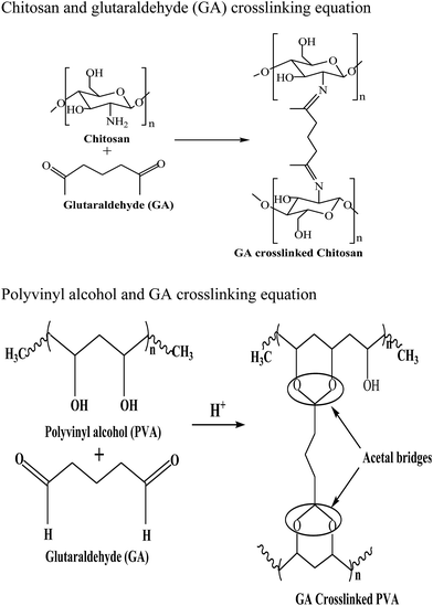 |
| | Scheme 1 Crosslinking of chitosan and PVA with glutaraldehyde. | |
2.4. Characterization of electrospun nanofibres
Images of electrospun nanofibres were obtained with a field emission scanning electron microscope (Carl Zeiss NTS GmbH, Oberkochen (Germany) Model: SUPRA 40VP) operated at an accelerating voltage of 10 kV. Prior to imaging, the samples mounted on copper stubs were coated with gold for better conductivity during imaging. FT-IR spectra were recorded with a Nicolet 17DSX FT-IR spectrometer. The X-ray diffraction (XRD) patterns of nanofibers were measured using a Hecus X-ray Systems GmbH, Graz (Austria) Model: S3 MICRO.
2.5. Performance of the CPF towards toxic ion uptake
Adsorption experiments were carried out by a batch technique. The optimum pH for the uptake of these ions was obtained from an aqueous solution containing various toxic ions (Cr(VI) 10.0 mg L−1; As(III)/As(V) 2.3 mg L−1; F− 1.0 mg L−1). The initial pH of the solution was varied from 2 to 9 using an aqueous solution of NaOH or HCl with 20 mg of CPF mat in a final volume of 20 ml. At the end of the equilibrium time, the content was separated by filtration with a 0.22 μm pore size filter paper, and the content of arsenic in solution was analyzed by inductive coupled plasma-mass spectrometry (ICP-MS) (Thermo Scientific, XSERIES 2) for As(III) and As(V). The analysis of Cr(VI) was carried out via the diphenyl carbazide method.19 The analysis of fluoride ions in the filtrate was carried out using a fluoride selective electrode and ORION fluoride meter. During the fluoride analysis, the addition of total ionic strength adjustment buffer (TISAB) solution eliminated the interference caused by the complexing ions. The electrode was calibrated daily with a series of 5 or more fluoride standard solutions within the linear working range of the fluoride electrode. All the experiments were carried out twice. The amount of the ions adsorbed (mg) per unit mass of CPF (g), qe, was obtained by a mass balance using the following equation:| |
 | (1) |
where Ci and Ce are the initial and equilibrium concentrations of the metal ion (mg L−1), m is the dry mass of the nanofibre mat (g) and V is the volume of the solution (L). The percent extraction efficiency of the sorbent can be calculated using the following equation:| | |
Extraction efficiency (%) = (C0 − Ce)/C0 × 100
| (2) |
For kinetic studies, the initial concentration of ions was maintained as described earlier. Except for Cr(VI), for which the initial pH was maintained at 3, the pH for all the other ions was adjusted to 7, and the solutions were equilibrated. Samples were withdrawn at regular intervals and analysed for their respective analyte. For isotherm experiments, about 20 mg of adsorbent (CPF) was added to a beaker containing 20 ml of 0.1–10 mg L−1 of As(V)/As(III)/F and 100–1000 mg L−1 Cr(VI) solution, and it was equilibrated. All the other parameters were maintained as before and the amount of toxic ions adsorbed was calculated using the eqn (1).
2.6. Antibacterial activity
The antibacterial activity was ascertained for the prepared chitosan/PVA (CP) and chitosan/PVA/Fe nanofiber (CPF) mats against gram negative Escherichia coli (E. coli) bacterial strain. The E. coli (K-12) strain was obtained from the National Laboratory in India and cultured in Luria–Bertani broth (L.B broth) containing 10 g L−1 tryptone, 5 g L−1 yeast extract, and 10 g L−1 NaCl for 24 h at 37 °C. The antibacterial analysis was performed by the plate count method in LB agar medium (10 g L−1 tryptone, 5 g L−1 yeast extract, 10 g L−1 NaCl and 15 g L−1 agar) with incubation at 37 °C for 24 h. Then, 1 ml of bacterial culture LB medium was diluted in 50 ml of sterilized DI water. Different amounts (0.05 to 0.3 g) of the mats were added to the bacterial solution and incubated in a shaking incubator at 37 °C with a speed of 120 rpm. Samples (100 μl) were withdrawn from the incubated conical flasks at different time intervals (3, 6, 12, and 24 h) and spread onto LB agar plates. The initial bacterial concentration was approximately 104–105 CFU ml−1. The bacterial solution without CP and CPF nanofiber mats served as control. The antibacterial analysis was carried out for 24 h. The analysis was performed in duplicate to ensure the reproducibility.
3. Results and discussions
3.1. Characterization of nanofibres
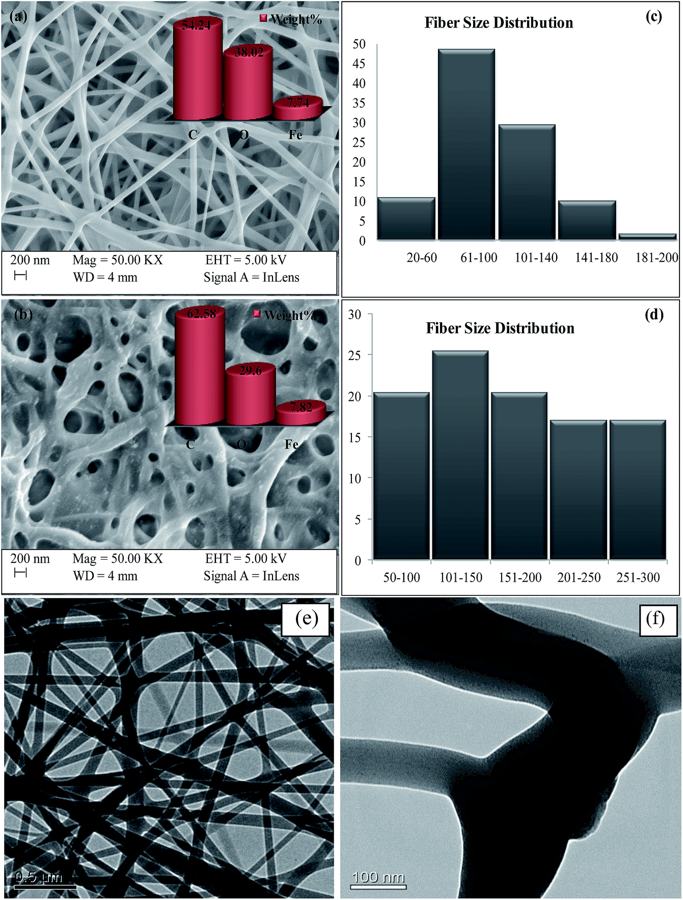
3.1.1 Electron microscopy and fibre size distribution. The morphology of electrospun nanofibers is influenced by various parameters such as flow rate, applied voltage, tip to collector distance and properties of polymer solutions.20 The morphology of the chitosan/PVA/Fe electrospun nanofiber mat was characterized by scanning electron microscopy. Fig. 1a shows the SEM image of the as-spun chitosan/PVA/Fe nanofiber mat, which has a nonbeaded fibrous structure, and Fig. 1b shows the SEM image of a glutaraldehyde (2% in methanol) crosslinked chitosan/PVA/Fe electrospun nanofiber mat. It was observed that the thickness of the fibers present in the fibrous mat slightly increases because of the hydrophilic character of few untreated alcoholic groups of PVA present in the fibrous mat. The elemental distribution of fiber mats shown in Fig. 1a and b confirms the presence of carbon, oxygen and iron in the fibrous mats. TEM micrographs (Fig. 1e and f) also support the non-uniform nanofibrous structure of the mats. Furthermore, it should be noted that Fe is uniformly dissolved in the fibres and iron nanoparticles are absent even in high resolution TEM (Fig. 1f).
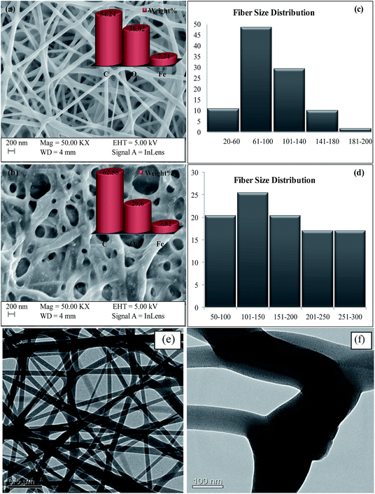 |
| | Fig. 1 (a) SEM image of the as-spun CPF, (b) glutaraldehyde crosslinked CPF, (c) fibre size distribution of the as-spun CPF, (d) fibre size distribution of glutaraldehyde crosslinked CPF, (e) and (f) TEM micrographs of the as-spun CPF. | |
Fibre size distribution (diameter of the fibres) was plotted with the help of ImageJ software,21 and the results obtained are shown in Fig. 1c and d. It is evident from Fig. 1c that the sizes of around 59% of the fibres were less than 100 nm and the other 41% of fibres were found to have sizes in the range of 100–200 nm, which is less than that of pure PVA fibres, as reported in the literature.12 The reduction in fibre size is because of the increment of charge density due to the addition of chitosan, a cationic polysaccharide, in the electrospinning jet, leading to higher elongation forces due to the higher conductivity of the polymeric solution, resulting in the thinner diameter of fibres.22 In the case of crosslinked fibre mats, fibre size distribution was found to be slightly higher (Fig. 1d). Around 45% of fibres had size less than 150 nm and the remaining 55% of fibres were found to have size in the range of 150–300 nm. The increment in fibre size is because of the hydrophilic character of PVA present in the mat. The porosity of virgin and crosslinked chitosan/PVA/Fe nanofibre mats was found to be 30% and 60%, respectively. The lower porosity of the virgin mat in aqueous solution could be attributed to the distorted fibrous structures.14 The amount of glutaraldehyde used was optimized such that free amino groups existed on the nanofibres for complexation reaction with the metal ions.14 Furthermore, the presence of primary amino groups in CPF was confirmed by FTIR studies, which are detailed in Section 3.1.2.
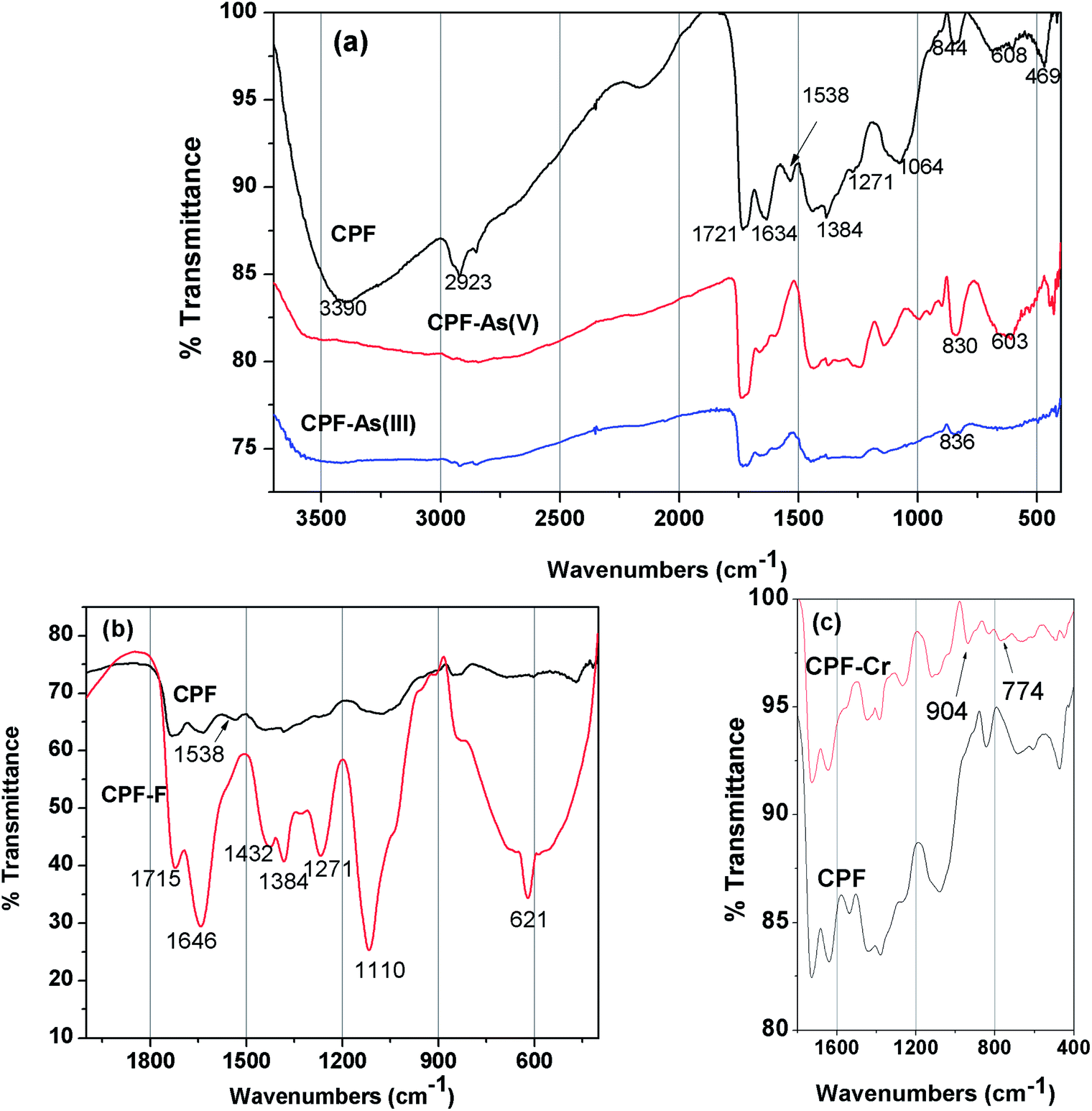
3.1.2 FTIR spectra. FTIR spectra of the unloaded CPF (Fig. 2a) exhibited broad peak at 3390 cm−1 due to the superimposition of O–H and –N–H vibrations. The C–H stretching vibration of the polysaccharide backbone is manifested through a strong peak at 2923 cm−1. The sharp peak at 1721 cm−1 could be attributed to the C–O stretching vibration The band at 1538 cm−1could be attributed to the bending vibration of the free primary amino group on the chitosan backbone. The crosslinking between the aldehydic groups of glutaraldehyde and amino groups of chitosan to form a Schiff base is evident from the peak at 1634 cm−1, which corresponds to –C![[double bond, length as m-dash]](https://www.rsc.org/images/entities/char_e001.gif) N vibration. Additional peaks at 844, 608 and 469 cm−1 confirm the Fe–OH structural vibration.23 The changes observed in the FTIR spectra after As(V) and As(III) loading are also shown in Fig. 2a. After metal ion loading, the peak at 3390 cm−1 is suppressed, which might be attributed to the interaction of arsenic ions with the functional groups present in the chitosan (–OH and –NH2). Because of the complexation of Fe(III) with As(III)/As(V) to form ferric arsenite or ferric arsenate, changes in Fe–OH vibration are observed. In the case of As(V), a peak shift from 844 to 830 cm−1 and from 608 to 603 cm−1 was observed.24 However, after As(III) loading, a peak at 836 cm−1 is observed due to the formation of ferric arsenite.25 In Fig. 2b and a peak at 1538 cm−1 corresponding to NH3+ is diminished after fluoride loading because of the strong electrostatic attraction between the positively charged NH3+ and negatively charged fluoride ions. A similar observation was recorded by Huang et al.26 Furthermore, the appearance of a sharp peak at 621 cm−1 and formation of a broad peak at 822 cm−1 after fluoride loading indicated the formation of O⋯F27 and OH⋯F28 bonds, respectively. The IR spectra (Fig. 2c) of chromium loaded CPF showed perceptible changes in comparison with that of unused CPF, in particular in the region of 600 to 1200 cm−1. Two new appeared peaks at 774 and 904 cm−1, attributed to the Cr–O and CrO bonds from the Cr(VI) species, which suggests that Cr(VI) was adsorbed on the surface of CPF.29
N vibration. Additional peaks at 844, 608 and 469 cm−1 confirm the Fe–OH structural vibration.23 The changes observed in the FTIR spectra after As(V) and As(III) loading are also shown in Fig. 2a. After metal ion loading, the peak at 3390 cm−1 is suppressed, which might be attributed to the interaction of arsenic ions with the functional groups present in the chitosan (–OH and –NH2). Because of the complexation of Fe(III) with As(III)/As(V) to form ferric arsenite or ferric arsenate, changes in Fe–OH vibration are observed. In the case of As(V), a peak shift from 844 to 830 cm−1 and from 608 to 603 cm−1 was observed.24 However, after As(III) loading, a peak at 836 cm−1 is observed due to the formation of ferric arsenite.25 In Fig. 2b and a peak at 1538 cm−1 corresponding to NH3+ is diminished after fluoride loading because of the strong electrostatic attraction between the positively charged NH3+ and negatively charged fluoride ions. A similar observation was recorded by Huang et al.26 Furthermore, the appearance of a sharp peak at 621 cm−1 and formation of a broad peak at 822 cm−1 after fluoride loading indicated the formation of O⋯F27 and OH⋯F28 bonds, respectively. The IR spectra (Fig. 2c) of chromium loaded CPF showed perceptible changes in comparison with that of unused CPF, in particular in the region of 600 to 1200 cm−1. Two new appeared peaks at 774 and 904 cm−1, attributed to the Cr–O and CrO bonds from the Cr(VI) species, which suggests that Cr(VI) was adsorbed on the surface of CPF.29
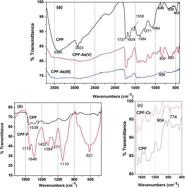 |
| | Fig. 2 FTIR spectra of (a) CPF and As(III) and As(V) loaded CPF, (b) CPF and fluoride loaded CPF, (c) CPF and Cr(VI) loaded CPF. | |
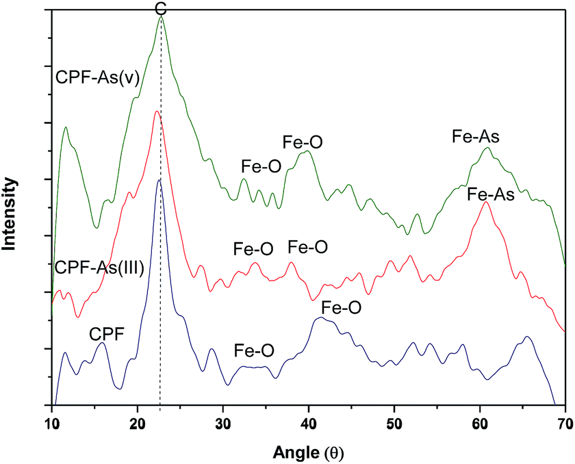
3.1.3 XRD measurements. The X-ray diffraction (XRD) patterns of the virgin CPF and As(III) and As(V) loaded CPF nanofibres were recorded at ambient temperature. The samples were irradiated with a monochromatized Cu KR (1.5406 Å) X-ray source and analyzed between 10° and 70° (2θ). The operating voltage and current used were 45 kV and 40 mA, respectively. Fig. 3 reveals that the CPF nanofibrous membranes possessed one sharp diffraction peak at a 2θ value around 22.7° and another broad diffraction peak at 40.1°. The sharp peak corresponds to the reflection peak of electrospun chitosan/PVA nanofibres,30 and the broad peaks around 31.6° and 42° correspond to amorphous ferric oxide crystalline phases.31 It is also evident from the figure that after arsenic loading, distinct peaks appeared at 60.9°, which could be attributed to the formation of ferric arsenate.32
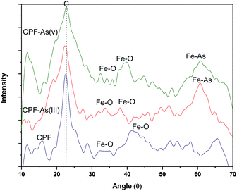 |
| | Fig. 3 XRD patterns of CPF and As(III)/As(V) loaded CPF. | |
3.2. Adsorption experiments
Adsorption studies were carried out at room temperature to study the effect of adsorption time and initial pH. For the variation of pH experiments, only the initial pH of the aqueous solution was varied and the pH was not maintained during the sorption experiments. The obtained results are shown in Fig. 4. In pH variation studies (Fig. 4a), it is evident that maximum adsorption of Cr(VI) occurs at pH 3. In the pH range of 2 to 5, the predominant Cr(VI) species is HCrO4−,33 which can chelate with Fe(III) present in the CPF mat via the ligand exchange mechanism.34 In the case of arsenic, the maximum adsorptions of both trivalent and pentavalent species are observed at pH values between 6 and 7.5. It is reported that iron(III) oxides exist in the cationic monomeric form of Fe(OH)2+ below pH 7.35 Arsenate exists as H2AsO4− or HASO42− at pH values greater than 3, and arsenite exists as neutral species H3AsO3 at pH values less than 9.35 Though both arsenite and arsenate are removed from the solution by the formation of ferric arsenite and arsenate, the formation of ferric arsenate is more facilitated by the ionic attraction, as evident from the pH results. Therefore, initially, ionic attraction takes place between anionic arsenate species and cationic ferric hydroxide, followed by a ligand exchange reaction leading to ferric arsenate. A similar observation is reported by many researchers for the removal of arsenic by either iron oxide or iron coated materials.35 In addition, arsenate ions are attracted to the protonated amino groups of chitosan by electrostatic attraction followed by reduction and complexation with protonated/deprotonated amino groups.36 Further FTIR (Fig. 2a) and XRD spectra (Fig. 3) confirm the formation of ferric arsenate. It is apparent that maximum fluoride adsorption occurred at pH 7.5. The lower adsorption of fluoride ions at pH < 7.5 could be attributed to the formation of hydrofluoric acid. Under alkaline conditions, the decrease in fluoride uptake could be due to the competition from hydroxyl ions. From the pH studies, it is evident that fluoride sorption takes place by the electrostatic attraction between the protonated amino groups of chitosan and fluoride ions. A similar observation has been observed elsewhere.37 Furthermore, the interaction of fluoride ions with hydroxyl groups of the chitosan by ion exchange or hydrogen bonding is also plausible. This is confirmed by the FTIR studies (Fig. 2b). Similarly, in the case of arsenate and chromate, electrostatic interaction between the protonated amino groups of the chitosan and anions is also possible. A schematic representation of the sorption of crosslinked chitosan mat with different ions studied is depicted in Scheme 2.
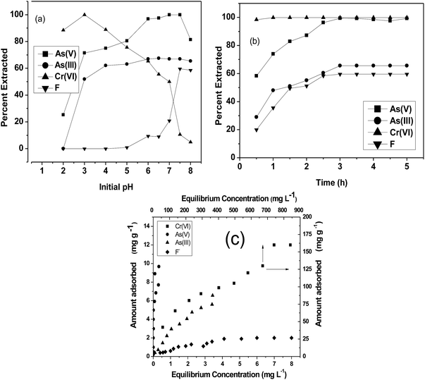 |
| | Fig. 4 (a) Effect on initial pH on sorption; (b) kinetics plot; (c) equilibrium isotherm plots of Cr(VI), As(III), As(V) and F and CPF system. | |
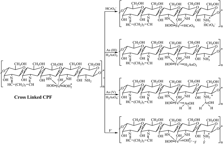 |
| | Scheme 2 Schematic representation of the mechanism of interaction of crosslinked CPF with As(III), As(V), Cr(VI) and F. | |
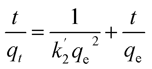
Fig. 4b shows the time profiles of As(III), As(V), Cr(VI) and F− adsorption by CPF in batch mode. From the results, it is evident that Cr(VI) sorption onto CPF is very fast and >98% sorption was observed within 30 min. For the other ions, complete equilibrium was achieved at an equilibration time > 2.5 h. The obtained data were modeled by Ho's pseudo second order equation38 given by
| |
 | (3) |
where
k′2 is the pseudo second-order rate constant of adsorption (g mg
−1 h) and
qe and
qt are the amounts of analyte ion sorbed (mg g
−1) at equilibrium and at time
t, respectively. Linear plots of
t/
qt vs. t for the various ions yielded straight lines with the correlation coefficients of >0.945. The calculated values of various constants are tabulated in
Table 1.
Table 1 Langmuir equilibrium isotherm and pseudo second order model constants
| Analyte |
Langmuir isotherm model |
Pseudo second order model |
| Qb (mg g−1) |
b (L mg−1) |
R2 |
k′2(g mg−1 h) |
R2 |
| As(III) |
32.3 |
0.082 |
0.99 |
1.304 |
0.94 |
| As(V) |
83.3 |
4.000 |
0.91 |
0.905 |
0.99 |
| Cr(VI) |
166.7 |
0.006 |
0.97 |
10.000 |
1.00 |
| F− |
2.5 |
0.413 |
0.95 |
1.404 |
0.98 |
The equilibrium sorption isotherms of different ions were studied, and the results obtained are shown in Fig. 4c. The values were modeled using a linearized Langmuir isotherm
where
qe is the amount of solute adsorbed (mg g
−1) at equilibrium and
Ce is the equilibrium concentration (mg L
−1). The empirical constants
Q and
b denote the monolayer capacity and energy of adsorption, respectively, and were calculated from the slope and intercept of the plot between 1/
Ce and 1/
qe. The values obtained are shown in
Table 1. The maximum adsorption capacities of Cr(
VI), As(
V), As(
III) and F were found to be 166.7, 83.3, 32.3 and 2.5 mg g
−1, respectively. The adsorption capacity obtained for Cr(
VI) is higher than those for other reported biosorbents like magnetic chitosan hydrogel (144.9 mg g
−1),
17 2013), sugarcane bagasse (5.09 mg g
−1),
39 magnetic particles (Fe
3O
4) immobilized onto PEI/acrylate beads (109.2 mg g
−1),
40 alginate (42.6 mg g
−1),
41 activated carbon and
Bacillus subtilis (19.43 mg g
−1).
42 In the case of arsenic species, it is observed that the adsorption capacity of CPF towards As(
V) was 2.6 times higher than that towards As(
III). This could be attributed to the prevalent electrostatic attraction between anionic arsenic species and the cationic surface charge of the sorbent, which aids the rapid complexation of arsenic with Fe(
III), leading to the formation of ferric arsenate. Complexation of Fe(
III) with arsenite or arsenate has been reported by other researchers.
12,16 It is also noteworthy that the adsorption capacity obtained for CPF towards the removal of arsenate was higher than the recently reported Fe(
III) incorporated PVA nanofibres (36 mg g
−1 As(
V)),
12 zerovalent iron incorporated chitosan nanofibres (1.65 mg g
−1 As(
III); 2.29 mg g
−1 As(
V)),
15 chitosan/PVA nanofiber (1.68 mg g
−1 As(
III); 0.56 As(
V) mg g
−1)
14 and iron chitosan flakes (16.15 mg g
−1 As(
III); 22.47 mg g
−1 As(
V)).
16 Although the CPF nanofibres exhibited a high capacity towards Cr(
VI), As(
III) and As(
V), their capacity towards fluoride was comparatively less. The fluoride uptake capacity of CPF is comparable to that of the most commonly and widely used sorbent,
i.e. activated alumina (2.41 mg g
−1).
43
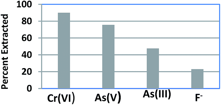
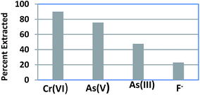
3.3. Selectivity studies
Selectivity studies were conducted by equilibrating a mixture of 5 ppm each of Cr(VI), As(III), As(V) and F− in 100 ml with 0.1 g of CPF mat for 3 h at pH 7. After equilibration, the solutions were filtered and analyzed for various ions. The selectivity performances of CPF are summarized in Fig. 5. The selectivity order for CPF toward the investigated anions followed the sequence Cr(VI) > As(V) > As(III) > F−. It should be noteworthy that the optimum pH for Cr(VI) adsorption is 3, and around 90% of the sorption took place at pH 7.
 |
| | Fig. 5 Selectivity studies. | |
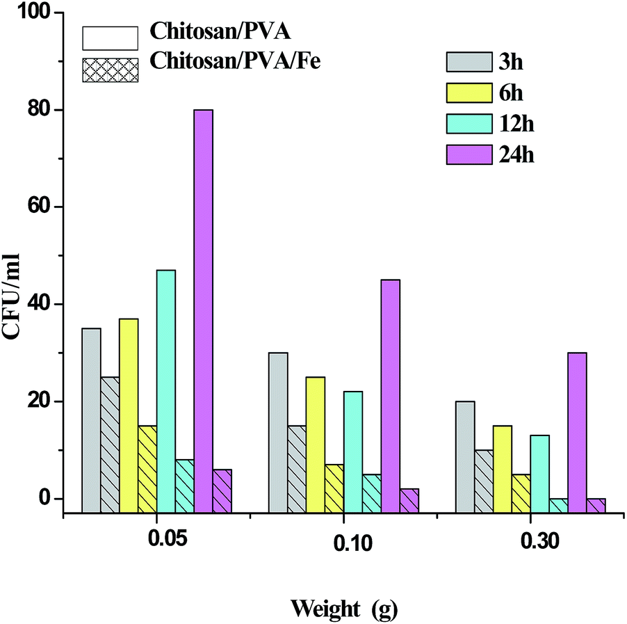
3.4. Antibacterial activity
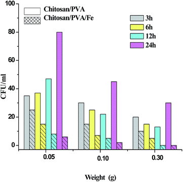
Fig. 6 shows the test results for chitosan/PVA (CP) and chitosan/PVA/Fe (CPF) nanofiber mats against E. coli bacterial strain. The inhibitory effect of nanofibers were determined on the basis of the number of colonies found in an LB agar plate. As observed from the Fig. 6, the prepared CPF nanofiber mats had a superior inhibitory effect compared to the CP nanofiber mats against E. coli. It was also observed that this inhibitory effect against E. coli bacterial strain increased with increasing amount of prepared CPF mats. The larger amount (0.3 g) of CPF nanofiber mats completely inhibited the bacterial colony at approximately 12 h, which showed the relatively superior performance. However, the lower amounts (0.05 and 0.1 g) of CPF mat showed a gradual decrease in bacterial growth. In the case of CP nanofiber mats, it is evident that the mat has the capability to reduce bacteria only for 12 h, and after 12 h the number of colonies increased with time. This observation is in accordance with the earlier reports.44 The inhibitory effect of the CPF mat is due to the presence of chitosan and Fe metal prevalent in the mat. As mentioned earlier in the text, chitosan exhibits antibacterial activity against gram negative and gram positive bacterial strains because of the interaction of poly-cationic amines with negatively charged substances at the cell surface of bacteria.7 Fe metal also has a bactericidal effect because of the generation of reactive oxidative species that cause cellular disruption, which leads to cell death.45
 |
| | Fig. 6 Antibacterial activity. | |
4. Conclusions
A novel nanofibrous composite mat consisting of chitosan/Fe(III)/PVA was synthesized by an electrospinning technique. The prepared mats were stabilized by crosslinking with glutaraldehyde and characterized by various techniques. The versatility of the mat was demonstrated by their high sorption capacity towards various toxic anions, such as As(III), As(V), Cr(VI) and F−. The equilibrium data were modeled using a linearized Langmuir model, and the adsorption capacities of Cr(VI), As(III), As(V) and F− were found to be 166.7, 83.3, 32.3 and 2.5 mg g−1, respectively. Furthermore, the CPF mat exhibited disinfection control towards E. coli bacteria. Thus, the removal of both toxic contaminants coupled with antibacterial activity makes CPF nanofibrous mats a promising candidate for the drinking water purification sector.
Notes and references
- B. I. Escher and K. Fenner, Environ. Sci. Technol., 2011, 45, 3835 CrossRef CAS PubMed.
- EPA National Primary Drinking Water Standards 2009,http://www.epa.gov/safewater/contaminants/index.html for more information.
- S. S. Gupta and K. G. Bhattacharyya, Adv. Colloid Interface Sci., 2011, 162, 39 CrossRef PubMed.
- F. Fu and Q. Wang, J. Environ. Manage., 2011, 92, 407 CrossRef CAS PubMed.
- K. Pillay, E. M. Cukrowska and N. J. Coville, J. Hazard. Mater., 2009, 166, 1067 CrossRef CAS PubMed.
- E. Guibal, Sep. Purif. Technol., 2004, 38, 43 CrossRef CAS PubMed.
- N. M. Angelova, I. Rashkov, V. Maximova, S. Bogdanova and A. Domard, J. Bioact. Compat. Polym., 1995, 10, 285–298 CAS.
- K. Desai, K. Kit, J. J. Li, P. M. Davidson, S. Zivanovic and H. Meyer, Polymer, 2009, 50, 3661 CrossRef CAS PubMed.
- S. Haider and S. Y. Park, J. Membr. Sci., 2009, 328, 90 CrossRef CAS PubMed.
- D. Bjorge, N. Daels, S. d. Vrieze, P. Dejans, T. V. Camp, W. Audenaert, J. Hogie, P. Westbroek, K. D. Clerck and S. W. H. Hulle, Desalination, 2009, 249, 942 CrossRef CAS PubMed.
- N. L. Lala, R. Ramaseshan, B. Li, S. Sundarrajan, R. S. Barhate, Y. J. Liu and S. Ramakrishna, Biotechnol. Bioeng., 2007, 97, 1357 CrossRef CAS PubMed.
- N. Mahanta and S. Valiyaveettil, RSC Adv., 2013, 3, 2776 RSC.
- N. Horzum, M. M. Demir, M. Nairatc and T. Shahwan, RSC Adv., 2013, 3, 37828 RSC.
- D. Chauhan, J. Dwivedi and N. Sankararamakrishnan, Environ. Sci. Pollut. Res., 2014, 21, 9430–9442 CrossRef CAS PubMed.
- Y. Zhang, X. Huang, B. Duan, L. Wu, S. Li and X. Yuan, Colloid Polym. Sci., 2007, 285, 855 CAS.
- A. Gupta, V. S. Chauhan and N. Sankararamakrishnan, Water Res., 2009, 43, 3862 CrossRef CAS PubMed.
- Z. Yu, X. Zhang and Y. Huang, Ind. Eng. Chem. Res., 2013, 52, 11956 CrossRef CAS.
- C. Tang, C. D. Saquing, J. R. Harding and S. A. Khan, Macromolecules, 2010, 43, 630 CrossRef CAS.
- APHA, Standard Methods for the Examination of Water and Wastewater, American Public Health Association, Washington, D.C, 20th edn, 1998 Search PubMed.
- J. M. Deitzel, J. Kleinmeyer, D. Harris and N. C. B. Tan, Polymer, 2001, 42, 261 CrossRef CAS.
- Z. X. Meng, W. Zheng, L. Li and Y. F. Zheng, Mater. Chem. Phys., 2011, 125, 606 CrossRef CAS PubMed.
- Y. T. Jia, J. Gong, X. H. Gu, H. Y. Kim, J. Dong and X. Y. Shen, Carbohydr. Polym., 2007, 67, 403 CrossRef CAS PubMed.
- J. E. Amonette and D. Rai, Clays Clay Miner., 1990, 38, 129 CAS.
- N. Sankaramakrishnan, A. Gupta and S. R. Vidyarthi, J. Environ. Chem. Eng., 2014, 2, 802 CrossRef PubMed.
- Y. Jia, X. Liying, X. Wang and G. P. Demopoulos, Geochim. Cosmochim. Acta, 2007, 71, 1643 CrossRef CAS PubMed.
- R. Huang, B. Yang, Q. Liu and K. Ding, J. Fluorine Chem., 2012, 141, 29 CrossRef CAS PubMed.
- P. K. Raul, R. R. Devi, I. M. Umlong, S. Banerjee, L. Singh and M. Purkhait, J. Nanosci. Nanotechnol., 2012, 12, 3922 CrossRef CAS PubMed.
- C. S. Sundaram, N. Viswanathan and S. Meenakshi, J. Hazard. Mater., 2008, 155, 206 CrossRef CAS PubMed.
- N. Sankararamakrishnan, A. Dixit, L. Iyengar and R. Sanghi, Bioresour. Technol., 2006, 97, 2377 CrossRef CAS PubMed.
- Y. T. Jia, J. Gong, X. H. Gu, H. Y. Kim, J. Dong and X. Y. Shen, Carbohydr. Polym., 2007, 67, 403 CrossRef CAS PubMed.
- Z. Swiatkowska-Warkocka, K. Kawaguchi, H. Wang, Y. Katou and N. Koshizaki, Nanoscale Res. Lett., 2011, 6, 226 CrossRef PubMed.
- Y. Jia, L. Xu, X. Wang and G. P. Demopoulos, Infrared spectroscopic and X-ray diffraction characterization of the nature of adsorbed arsenate on ferrihydrite, Geochim. Cosmochim. Acta, 2007, 71, 1643 CrossRef CAS PubMed.
- Dionex, Technical note 26 LPN 034398-02 1M 1/98, 1998, http://www.dionex.com/enus/webdocs/4428TN26_16May07_LPN034398-02.pdf.
- A. C. Zimmermann, A. Mecabô, T. Fagundes and C. A. Rodrigues, J. Hazard. Mater., 2010, 179, 192 CrossRef CAS PubMed.
- I. A. Katsoyiannis and A. I. Zouboulis, Water Res., 2002, 36, 5141 CrossRef CAS.
- K. C. Man, Ph.D. Thesis, Hong Kong University of Science and technology, 2009.
- B. Petrusevski, S. Sharma, J. C. Schippers and K. Shordt, Arsenic in Drinking Water, Thematic Overview Paper 17, IRC International Water and Sanitation Centre, 2007 Search PubMed.
- Y. S. Ho and G. McKay, Process Biochem., 1999, 34, 451 CrossRef CAS.
- C. Alomá, I. Rodríguez, M. Calero and G. Blázquez, Desalin. Water Treat., 2014, 52, 5912–5922 CrossRef.
- G. Bayramoglu and M. Y. Arica, Chem. Eng. J., 2008, 139, 20 CrossRef CAS PubMed.
- C. Bertagnolli, M. G. C. da Silva and E. Guibal, Chem. Eng. J., 2014, 237, 362 CrossRef CAS PubMed.
- C. Sukumar, G. Gowthami, R. Nitya, V. Janaki, S. K. Kannan and K. Shanthi, Environ. Earth Sci., 2014, 72, 839–847 CrossRef CAS.
- V. S. Chauhan, P. K. Dwivedi and L. Iyengar, J. Hazard. Mater., 2007, 139, 103 CrossRef CAS PubMed.
- S. J. Jeon, M. Oh, W.-S. Yeo, K. N. Galvao and K. C. Jeong, PLoS One, 2014, 9, e92723 Search PubMed.
- B. S. Inbaraj, T.-Y. Tsai and B.-H. Chen, Sci. Technol. Adv. Mater., 2012, 13, 1 Search PubMed.
|
| This journal is © The Royal Society of Chemistry 2014 |
Click here to see how this site uses Cookies. View our privacy policy here.