
Nanoscale analysis of functionalized polythiophene surfaces: the effects of electropolymerization methods and thermal treatment
Jae-Eun Leea,
Shyh-Chyang Luobc,
Bo Zhubd,
Joon Won Park*a and
Hsiao-hua Yu*be
aDepartment of Chemistry, Pohang University of Science and Technology, San 31 Hyoja-dong, Pohang, 790-784, Korea. E-mail: jwpark@postech.ac.kr; Fax: +82-54-279-0653; Tel: +82-54-279-2119
bResponsive Organic Materials Laboratory, RIKEN 2-1 Hirosawa, Wako, Saitama 351-0198, Japan
cDepartment of Materials Science and Engineering, National Cheng Kung University, 1 University Road, Tainan 70101, Taiwan
dState Key Lab for Modification of Chemical Fibers and Polymer Materials, College of Materials Science and Engineering, Donghua University, 2999 North Renmin Road Songjiang, Shanghai, 201600, China
eInstitute of Chemistry, Academia Sinica, 128 Academic Road Sec. 2 Nankang, Taipei 115, Taiwan. E-mail: bruceyu@gate.sinica.edu.tw; Fax: +886-2-2783-1237; Tel: +886-2-2789-8634
First published on 14th November 2014
Abstract
Functionalized poly(3,4-ethylenedioxythiophene) (PEDOT) thin films fabricated by cyclic voltammetry and potentiostatic electropolymerization were analyzed by adhesion mapping. Two monomers, zwitterionic phosphorylcholine EDOT (EDOT-PC) and hydroxymethyl EDOT (EDOT-OH), were used to prepare the corresponding homopolymers PEDOT-PC and PEDOT-OH. Force–extension curve-based atomic force microscopy (AFM) was used to generate nanoscale-resolution maps revealing the characteristic stretching behavior at each pixel. As expected, the maps for PEDOT-PC consisted mostly of pixels with long stretching curves, whereas the maps for PEDOT-OH consisted of pixels with short stretching curves. The number of pixels with short stretching curves was compared with the number of pixels with long stretching curves. For PEDOT-PC, the relative ratio of the pixels with long stretching increased with the rate of voltage change (or number of cycles) during electropolymerization. The relative ratio of short to long stretched pixels in the film fabricated by potentiostatic electropolymerization was as large as that of the film fabricated by cyclic voltammetry at the highest scan rate (400 mV s−1). The thermal annealing increased the number of pixels with short stretching, indicating that chain reorganization led to stronger interchain adhesion. For PEDOT-OH, the films were composed primarily of pixels with short stretching. The relative short to long stretching ratio was insensitive to the polymerization method. Our approach can be used to resolve the surface structure of polymer films at the nanoscale.
Introduction
Atomic force microscopy (AFM) is a useful tool for analyzing the physical and chemical characteristics of surfaces at the nanoscale.1,2 Information about the surface morphology, along with chemical force microscopy3 and adhesion force mapping,4 has allowed the nanoscale composition and structure of polymer surfaces to be unveiled under various conditions. Recently, these methods have been applied to analyze the stretching of polymer chains5–10 and to characterize polymeric surfaces.11–17 Furthermore, through proper functionalization of the AFM probe, one can follow specific chemical interactions, resulting in maps that reveal the physicochemical characteristics of a surface with nanoscale resolution.The structural properties of poly(3,4-ethylenedioxythiophene) (PEDOT) films are dependent on the preparation conditions, which include the electropolymerization method, solvents, electrolytes, and temperature. Thus, it is very important to choose experimental conditions that enable precise tuning of the PEDOT film.18–21 Functionalized EDOT monomers in aqueous microemulsions have been electropolymerized to provide films with smooth morphologies and outstanding biocompatibility.22–26 These conjugated polymers are of particular interest because they spontaneously assemble into nanostructures through a thermodynamic equilibration process. However, conventional tools cannot provide detailed data about the surface characteristics of these films. Thus, it has been challenging to obtain a full understanding of the nanodomain distribution throughout the electropolymerization process. We previously used force–extension curve-based AFM to analyze the surfaces of functionalized PEDOT copolymer films, obtaining adhesion maps that correlated well with the corresponding monomer composition.27 The maps also provided valuable information regarding the nanosized domains and their spatial distribution. Therefore, adhesion mapping is likely to reveal any nanostructural differences between PEDOT polymer films prepared by cyclic voltammetry and potentiostatic electropolymerization. In this report, we directly compared functionalized PEDOT homopolymer films prepared by these two methods. To induce specific interactions between the AFM tip and the conjugated backbone of the PEDOT, anthracene moieties were conjugated to the tip surface, as previously reported.
Experimental section
Materials
The silane coupling agent N-(3-(triethoxysilyl)propyl)-O-polyethylene oxide urethane (TPU) was purchased from Gelest, Inc. and was stored under nitrogen. All other chemicals and solvents were reagent grade and were purchased from Sigma-Aldrich unless otherwise noted. All of the solvents used to wash the probes were HPLC grade and were obtained from Mallinckrodt Baker. Ultrapure deionized (DI) water (18.2 MΩ cm) was obtained using a Milli-Q purification system (Millipore). Silicon nitride probes (PEN-0012-03; k = ∼16 pN nm−1) were purchased from NanoInk, Inc.AFM probe modification
A dendron-modified tip was prepared as previously reported.28 The silicon nitride probes were first oxidized by dipping the probes in an 80% nitric acid solution at 80 °C for 20 min. The probes were then washed and thoroughly rinsed with deionized water. The clean probes were dried in a vacuum chamber for 20 min and used immediately for the subsequent modification steps. For silylation, the probes were placed in 20 mL of anhydrous toluene with 0.20 mL of dissolved TPU under a nitrogen atmosphere for 4 h. Subsequently, the probes were washed briefly with toluene, baked at 110 °C for 30 min, and thoroughly rinsed sequentially with toluene and methanol. Finally, the probes were washed with methanol and dried under vacuum. To introduce the anthracene moiety, the probes were then placed in a methylene chloride solution with a small amount of dimethylformamide (DMF) containing 1.0 mM of a third-generation dendron (i.e., 27-acid) with a 9-anthrylmethoxycarbonyl group at its apex and the coupling agent 1,3-dicyclohexylcarbodiimide (DCC) (27 mM for the 27-acid) in the presence of 4-dimethylaminopyridine (DMAP) (0.90 mM) for 12 h. After the ester-forming reaction, the probes were thoroughly rinsed with a sequence of methylene chloride, methanol, and deionized water, before a final wash with methanol. The probes were then dried under vacuum. Through the esterification, a dendron with multiple carboxylic groups at its periphery was covalently linked to the silylated surface. The self-assembly process placed the anthracene moiety at the top surface of the probes.Electropolymerization of the functionalized PEDOT homopolymer films
Functionalized PEDOT homopolymer films were prepared by two electropolymerization methods on ITO electrodes: cyclic voltammetry (−0.6 to 1.4 V vs. Ag/AgCl at a scan rate of 100 mV s−1, 200 mV s−1, or 400 mV s−1) and potentiostatic electropolymerization (1.4 V vs. Ag/AgCl for 5 s).The electropolymerization was performed in aqueous solutions of functionalized EDOT monomers (0.010 M) and LiClO4 (0.10 M) in the presence of sodium dodecyl sulfate (SDS) (0.050 M) (Fig. 1). For the polymer films prepared by cyclic voltammetry, the total scan time was 80 s.
 | ||
| Fig. 1 Electropolymerization. (a–c) Cyclic voltammetry (−0.6 to 1.4 V vs. Ag/AgCl at a scan rate of (a) 100 mV s−1, (b) 200 mV s−1, and (c) 400 mV s−1). The total scan time for each case is 80 s. (d) Potentiostatic electropolymerization (1.4 V vs. Ag/AgCl for 5 s). | ||
AFM mapping
Force–extension curves were recorded with a ForceRobot 300 automated force spectroscope (JPK Instruments AG, Germany). The spring constant of each AFM probe was calibrated in solution using the thermal fluctuation method, which yielded values ranging from 15–25 pN nm−1. The measurements were performed in PBS (10 mM phosphate buffer, 2.7 mM KCl, 137 mM NaCl, pH 7.4) at room temperature. The adhesion images were obtained by recording force–extension curves during raster scanning of a 60 nm × 60 nm area. The scan area was divided into 20 × 20 (400) pixels. For accuracy, 10 curves were recorded at each pixel (4000 measurements per area) with a retract velocity of 540 nm s−1. The AFM tip was programmed to contact the surface with a force of 350 pN and to move a vertical distance of 450 nm. The force–extension curves were analyzed using JPK data-processing software.Results and discussion
Adhesion mapping of functionalized PEDOT homopolymer films
To obtain functionalized PEDOT homopolymer films, EDOT monomers, zwitterionic phosphorylcholine EDOT (EDOT-PC),29 and hydroxymethyl EDOT (EDOT-OH) were prepared by applying either cyclic voltammetry or potentiostatic electropolymerization (Fig. 1). Table 1 summarizes the characteristics of the PEDOT homopolymer films (PEDOT-PC and PEDOT-OH) prepared via these two electropolymerization methods. For cyclic voltammetry, the PEDOT-PC films were prepared at three different scan rates (100, 200, and 400 mV s−1), and the PEDOT-OH films were prepared at two different scan rates (100 and 200 mV s−1). The film thickness was primarily determined by the charges consumed during electropolymerization. Therefore, to ensure that the films prepared at different scan rates had a constant thickness, the number of cycles was increased in proportion to the scan rate such that the total polymerization time was constant. According to a previous study,22 films prepared in the presence of surfactants should have smooth surfaces, with a surface roughness of less than 10 nm. The scanning rate did not affect the surface roughness.| # | Homopolymer | Method | Condition |
|---|---|---|---|
| S1 | PEDOT-PC | Cyclic | Rate = 100 mV s−1 (2 cycles, −0.6 to 1.4 V) |
| S2 | PEDOT-PC | Cyclic | Rate = 200 mV s−1 (4 cycles, −0.6 to 1.4 V) |
| S3 | PEDOT-PC | Cyclic | Rate = 400 mV s−1 (8 cycles, −0.6 to 1.4 V) |
| S4 | PEDOT-PC | Potentiostatic | 1.4 V for 5 s |
| S5 | PEDOT-OH | Cyclic | Rate = 100 mV s−1 (2 cycles, −0.6 to 1.4 V) |
| S6 | PEDOT-OH | Cyclic | Rate = 200 mV s−1 (4 cycles, −0.6 to 1.4 V) |
| S7 | PEDOT-OH | Potentiostatic | 1.4 V for 5 s |
We used a commercially available dendron to introduce anthracene groups at the ends of the AFM tips using a well-established surface modification method that provided the appropriate surface chemistry.28,30 The anthracene tip also provided good contrast for the functionalized PEDOT homopolymer and copolymer films. To prepare the anthracene tips, the multiple carboxylic groups on the dendron periphery were covalently conjugated to the terminal hydroxyl group of the silane layer through esterification. Although the backbone of the dendron comprises an ethereal linkage and an amide linkage, an anthracene group is present at each apex (Fig. 2). To analyze the surface of the PEDOT homopolymer films, force–extension curves were recorded for a 60 nm × 60 nm area at intervals of 3.0 nm. A total of 10 curves were obtained at each pixel. As previously reported,27 the force–extension curves of the various shapes could be categorized into five groups (Fig. 3): (a) curves with a linear peak(s), (b) curves with a nonlinear and short stretching peak (distance from the contact point to the last peak position <20 nm), (c) curves with both a nonlinear and a linear peak(s), (d) curves with both a nonlinear and a long stretching peak(s) (distance from the contact point to the last peak position ≥20 nm), and (e) curves without a peak. These five types were further grouped into the following four subgroups: group I (types a and b), group II (type c), group III (type d), and group IV (type e). The curves in group II were complex forms featuring the characteristics of both groups I and III. In the adhesion maps, the color of the prevailing group was used. For example, green was used for the pixel if six curves belonged to group III (type d), one belonged to group I, one belonged to group II, and two belonged to group IV. Thus, each pixel was colored to show the prevailing group, i.e., pink for group I, gray for group II, green for group III, and black for group IV. In addition to counting the relative ratios of color groups (or pixels), the relative ratios between curve groups and their absolute percentages within a map were considered.
 | ||
| Fig. 2 Schematic of the functionalized PEDOT homopolymer surface and the anthracene-functionalized AFM tip. The insets depict the chemical structures of the dendron used for surface modification and the EDOT monomers. | ||
 | ||
| Fig. 3 Representative force–extension curves. The curves are categorized into five types. | ||
Influence of electropolymerization conditions on the ratio of pixels in the adhesion map
Adhesion maps for each PEDOT homopolymer (S1–S4: PEDOT-PC, S5–S7: PEDOT-OH) were obtained with a single anthracene tip (Fig. 4). As previously reported, force–extension curves exhibiting long stretching (group III) were mostly recorded for the PEDOT-PC homopolymer. For this homopolymer, green pixels were dominant in the adhesion map. Curves for short stretching (group I) were mainly observed for the PEDOT-OH homopolymer, where pink pixels dominated the map.27 For PEDOT-PC, observable changes in the map were observed when different polymerization conditions were employed, whereas the map for PEDOT-OH was rather insensitive to changing conditions. | ||
| Fig. 4 Adhesion maps of PEDOT-PC (S1–S4) and PEDOT-OH (S5–S7). Cyclic voltammetry method: (a and e) 2 cycles, (b and f) 4 cycles, and (c) 8 cycles (−0.6 to 1.4 V). Potentiostatic method: (d and g) 1.4 V for 5 s. The map size is 60 nm × 60 nm, and the pixel size is 3 nm × 3 nm. | ||
The number of green pixels increased with the cyclic voltammetry scan rate for PEDOT-PC (S1–S3). The relative ratios between the pink and green pixels for the three maps (Table 2 and Fig. 5) was 1![[thin space (1/6-em)]](https://www.rsc.org/images/entities/char_2009.gif) :2 (67% green pixels), 1:8.6 (90% green pixels), and 1:47 (98% green pixels), respectively. The relative ratios of the curves for group I and group III were 1.2:1 (45% group III curves), 1:3.2 (76% group III curves), and 1:11 (92% group III curves), respectively (Table 2). For PEDOT-PC prepared via the potentiostatic method (S4), the relative ratio of pink to green pixels was 1:29 (97% green pixels), which was similar to that of PEDOT-PC prepared via cyclic voltammetry at the highest scan rate (S3). The number of gray pixels (group II) for the potentiostatic method increased significantly. The relative ratio between the curves for group I and group III was 1:6.5 (87% for group III). In the case of PEDOT-OH, the relative ratios between the pink and green pixels for the three maps (Fig. 4e–g) were 22:1 (96% pink pixels), 40:1 (98% pink pixels), and 168:1 (99% pink pixels), respectively (Table 2). The relative ratios of the curves for group I and group III were 7.4:1 (88% for group I), 11:1 (92% for group I), and 40:1 (98% for group I), respectively. With respect to the pixel ratio, the values for the polymers prepared via the potentiostatic method were the same as those prepared at the intermediate scan rate. The number of gray pixels was the smallest for the polymer prepared by potentiostatic electropolymerization. However, the ratio based on the curve group was dependent upon the scan rate and the polymerization method.
:2 (67% green pixels), 1:8.6 (90% green pixels), and 1:47 (98% green pixels), respectively. The relative ratios of the curves for group I and group III were 1.2:1 (45% group III curves), 1:3.2 (76% group III curves), and 1:11 (92% group III curves), respectively (Table 2). For PEDOT-PC prepared via the potentiostatic method (S4), the relative ratio of pink to green pixels was 1:29 (97% green pixels), which was similar to that of PEDOT-PC prepared via cyclic voltammetry at the highest scan rate (S3). The number of gray pixels (group II) for the potentiostatic method increased significantly. The relative ratio between the curves for group I and group III was 1:6.5 (87% for group III). In the case of PEDOT-OH, the relative ratios between the pink and green pixels for the three maps (Fig. 4e–g) were 22:1 (96% pink pixels), 40:1 (98% pink pixels), and 168:1 (99% pink pixels), respectively (Table 2). The relative ratios of the curves for group I and group III were 7.4:1 (88% for group I), 11:1 (92% for group I), and 40:1 (98% for group I), respectively. With respect to the pixel ratio, the values for the polymers prepared via the potentiostatic method were the same as those prepared at the intermediate scan rate. The number of gray pixels was the smallest for the polymer prepared by potentiostatic electropolymerization. However, the ratio based on the curve group was dependent upon the scan rate and the polymerization method.
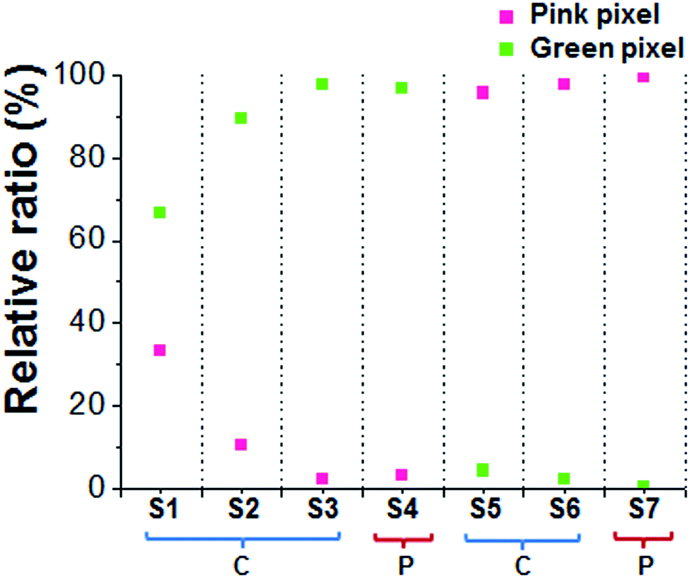 | ||
| Fig. 5 Relative ratios of pink to green pixels from the adhesion maps of functionalized PEDOT homopolymers (S1–S7). The letters C and P represent the cyclic voltammetry method and the potentiostatic method, respectively. | ||
For the PEDOT-PC homopolymer, the contrast increased with increasing scan rate for the cyclic voltammetry method. The highest scan rate for cyclic voltammetry method and the potentiostatic method resulted in adhesion maps with the highest contrast. This result indicates that the surface structure of the homopolymer is dependent upon the mode of applied potential, whereas the surface morphology is dependent upon the electropolymerization method, solvents, and electrolytes.19 Because non-orthogonal (lateral) stacking of the polymer chain with less entanglement should allow for long stretching upon retraction of the AFM tip, the highest scan rate for cyclic voltammetry and the potentiostatic method must be effective to such spatial arrangement of the polymer chains. Under these conditions, kinetically controlled polymerization at a high scan rate produces surface structures with weak interchain adhesion. The thermal annealing study supports this hypothesis (vide infra). In a buffer solution, whereas PEDOT-OH resists the long stretching, the weaker interchain adhesion of the PEDOT-PC allows the extended stretching, of which state is stabilized by zwitterions of the polymer chain.27 Therefore, short stretching events occur dominantly regardless of the stacking status (or the scanning rate) for the case of PEDOT-OH. Contrastingly the stacking mode of PEDOT-PC chain is dependent upon the rate of polymerization, and the chain turns to be less entangled at higher scanning rates. Whereas the relative ratios of green pixels are similar for S3 and S4, the relative ratio of curves belonging to group III is lower for the polymer prepared by the potentiostatic method. Thus far, it is unclear whether this difference is also associated with the stacking characteristics.
While pink pixels are consistently dominant for the PEDOT-OH films prepared under various conditions, the relative ratio of pixels was insensitive to the preparation conditions. The relative ratio of curves belonging to group I increased slightly from 88% to 92% at faster scan rates. The relative ratio increased to 98% and the number of gray pixels was markedly reduced for the polymers prepared by the potentiostatic method. The reduction of gray pixels indicates less stretchable stacking of the polymer chains. The relative ratio of the curve groups might be more sensitive to the surface structure and thus may serve as a better diagnostic for surface structural changes. Nevertheless, the colored maps aid in interpreting the two-dimensional structural distribution of the polymer films.
Effect of thermal annealing of the PEDOT-PC film
Adhesion mapping can be employed to investigate changes that occur upon thermal treatment of the polymers. The PEDOT-PC film prepared by the potentiostatic method (1.4 V for 5 s) was analyzed after annealing at 100 °C for 10 min under ambient conditions. As shown in Fig. 6c, the relative ratios of pink to green pixels for S4 and S4 (annealing) were 1:29 (97% green pixels) and 1:2.4 (71% green pixels), respectively. In addition, the relative ratios of the curves of group I and group III were 1:6.5 (87% group III curves) and 1:1.1 (52% group III curves), respectively. The combined numbers of pink and green pixels were similar for the two cases (152 vs. 142). The reduction in ratio is larger when the value based on the curve group is considered: 73% (71%/97%) based on the pixel number vs. 60% (52%/87%) based on the curve group. These results indicate that thermal annealing induced relaxation of the polymer chains, which reduced the local stress and promoted reorganization and packing of the polymer chains. In the end, the interaction between the polymer chains was strengthened and the ratio of long stretching was reduced. It is worth noting that adhesion mapping is sufficiently accurate to follow such changes. An additional advantage of adhesion mapping is the ability to unveil the distribution at the nanoscale. The map (Fig. 6b) unambiguously showed that these changes were uniformly distributed. Coloring the pixels according to the prevailing curve group facilitated the analysis of nanodomain formation and provided a tool for comparing the relative ratios of the curve groups in a map area that was more sensitive to the surface structure (or packing) of the corresponding polymers.
 | ||
| Fig. 6 Effect of the annealing treatment of a PEDOT-PC film prepared via the potentiostatic method. (a and b) Adhesion maps of two PEDOT-PC films before and after annealing. (c and d) Ratios of pink to green pixels (P:G) from the adhesion maps. aRelative ratio based on the number of corresponding pixels. bRelative ratio based on the number of group I and group III curves within the map. | ||
Conclusions
Using an anthracene-modified tip, force–extension curves for PEDOT-PC and PEDOT-OH prepared with different electropolymerization methods were obtained in a buffer solution. The stretching behavior of the homopolymer surface differed substantially according to the electropolymerization method and other experimental conditions. Adhesion maps with the highest relative ratios of pixels exhibiting long stretching were achieved by potentiostatic electropolymerization and by cyclic voltammetry at the highest scan rate for PEDOT-PC. Additionally, the analysis showed that the relative ratio of pixels with short stretching was less sensitive to the polymerization method and conditions for PEDOT-OH. The analysis indicated that the thermal annealing of PEDOT-PC led to structural changes on the surface. These nanoscale changes were uniformly distributed. Force–extension curve analysis and adhesion mapping provided valuable information regarding the surface structure of the polymeric films at the nanoscale, which is not accessible with using other conventional tools.Acknowledgements
This work was supported by the National Research Foundation of Korea (NRF) (NRF-2010-C00064). The research was also supported by RIKEN, Grants-In-Aid for Young Scientists (nos 22681016 and 23710138) from JSPS/MEXT and a Japan–Korea bilateral joint research project from JSPS.References
- G. Binnig, C. F. Quate and C. Gerber, Phys. Rev. Lett., 1986, 56, 930–933 CrossRef.
- C. Gerber and H. P. Lang, Nat. Nanotechnol., 2006, 1, 3–5 CrossRef CAS PubMed.
- C. D. Frisbie, L. F. Rozsnyai, A. Noy, M. S. Wrighton and C. M. Lieber, Science, 1994, 265, 2071–2074 CAS.
- M. Radmacher, J. P. Cleveland, M. Fritz, H. G. Hansma and P. K. Hansma, Biophys. J., 1994, 66, 2159–2165 CrossRef CAS.
- T. Hugel, M. Grosholz, H. Clausen-Schaumann, A. Pfau, H. Gaub and M. Seitz, Macromolecules, 2001, 34, 1039–1047 CrossRef CAS.
- C. Wang, W. Shi, W. Zhang, X. Zhang, Y. Katsumoto and Y. Ozaki, Nano Lett., 2002, 2, 1169–1172 CrossRef CAS.
- M. Seitz, C. Friedsam, W. Jöstl, T. Hugel and H. E. Gaub, ChemPhysChem, 2003, 4, 986–990 CrossRef PubMed.
- M. Geisler, B. N. Balzer and T. Hugel, Small, 2009, 5, 2864–2869 CrossRef CAS PubMed.
- K. Liu, Y. Song, W. Feng, N. Liu, W. Zhang and X. Zhang, J. Am. Chem. Soc., 2011, 133, 3226–3229 CrossRef CAS PubMed.
- L. Grebikova, P. Maroni, L. Muresan, B. Zhang, A. D. Schlüter and M. Borkovec, Macromolecules, 2013, 46, 3603–3610 CrossRef CAS.
- P. J. Eaton, P. Graham, J. R. Smith, J. D. Smart, T. G. Nevell and J. Tsibouklis, Langmuir, 2000, 16, 7887–7890 CrossRef CAS.
- H. Schönherr, Z. Hruska and G. J. Vancso, Macromolecules, 2000, 33, 4532–4537 CrossRef.
- A.-S. Duwez, C. Poleunis, P. Bertrand and B. Nysten, Langmuir, 2001, 17, 6351–6357 CrossRef CAS.
- A.-S. Duwez and B. Nysten, Langmuir, 2001, 17, 8287–8292 CrossRef CAS.
- H. Schönherr, C. L. Feng, N. Tomczak and G. J. Vancso, Macromol. Symp., 2005, 230, 149–152 CrossRef.
- J. M. Pelto, S. P. Haimi, A. S. Siljander, S. S. Miettinen, K. M. Tappura, M. J. Higgins and G. G. Wallace, Langmuir, 2013, 29, 6099–6108 CrossRef CAS PubMed.
- B. N. Balzer, S. Micciulla, S. Dodoo, M. Zerball, M. Gallei, M. Rehahn, R. v. Klitzing and T. Hugel, ACS Appl. Mater. Interfaces, 2013, 5, 6300–6306 CAS.
- D. H. Han, J. W. Kim and S. M. Park, J. Phys. Chem. B, 2006, 110, 14874–14880 CrossRef CAS PubMed.
- E. Poverenov, M. Li, A. Bitler and M. Bendikov, Chem. Mater., 2010, 22, 4019–4025 CrossRef CAS.
- S.-C. Luo, E.-S.-S. Liour and H.-h. Yu, Chem. Commun., 2010, 46, 4731–4733 RSC.
- T. Darmanin and F. Guittard, Prog. Polym. Sci., 2014, 39, 656–682 CrossRef CAS PubMed.
- S.-C. Luo, J. Sekine, B. Zhu, H. Zhao, A. Nakao and H.-h. Yu, ACS Nano, 2012, 6, 3018–3026 CrossRef CAS PubMed.
- S.-C. Luo, E. M. Ali, N. C. Tansil, H.-h. Yu, S. Gao, E. A. B. Kantchev and J. Y. Ying, Langmuir, 2008, 24, 8071–8077 CrossRef CAS PubMed.
- S.-C. Luo, H. Xie, N. Chen and H.-h. Yu, ACS Appl. Mater. Interfaces, 2009, 1, 1414–1419 CAS.
- J. Sekine, S.-C. Luo, S. Wang, B. Zhu, H.-R. Tseng and H.-h. Yu, Adv. Mater., 2011, 23, 4788–4792 CrossRef CAS PubMed.
- S.-C. Luo, E. A. B. Kantchev, B. Zhu, Y. W. Siang and H.-h. Yu, Chem. Commun., 2012, 48, 6942–6944 RSC.
- J.-E. Lee, J.-W. Kwak, J. W. Park, S.-C. Luo, B. Zhu and H.-h. Yu, Anal. Chem., 2014, 86, 6865–6871 CrossRef CAS PubMed.
- Y. J. Jung, B. J. Hong, W. Zhang, S. J. Tendler, P. M. Williams, S. Allen and J. W. Park, J. Am. Chem. Soc., 2007, 129, 9349–9355 CrossRef CAS PubMed.
- B. Zhu, S.-C. Luo, H. Zhao, H.-A. Lin, J. Sekine, A. Nakao, C. Chen, Y. Yamashita and H.-h. Yu, Nat. Commun., 2014, 5, 4523 Search PubMed.
- B. J. Hong, S. J. Oh, T. O. Youn, S. H. Kwon and J. W. Park, Langmuir, 2005, 21, 4257–4261 CrossRef CAS.
| This journal is © The Royal Society of Chemistry 2014 |