Facile fabrication of red phosphorus/TiO2 composites for lithium ion batteries

Han Xiaoa, Yang Xia*a, Yongping Gana, Hui Huanga, Chu Lianga, Xinyong Taoa, Lusheng Xub and Wenkui Zhang*a
aCollege of Materials Science and Engineering, Zhejiang University of Technology, Hangzhou, 310014, China. E-mail: nanoshine@zjut.edu.cn; msechem@zjut.edu.cn; Tel: +86-571-88320394
bCollege of Biological and Environmental Engineering, Zhejiang University of Technology, Hangzhou, 310014, China

Received 5th September 2014 , Accepted 7th November 2014

First published on 7th November 2014


Abstract

Red phosphorus (RP) is an attractive anode material with an ultrahigh specific capacity of 2596 mA h g−1. However, its rapid capacity decay attributed to the volume expansion during the lithiation process presents a noteworthy technical challenge. Meanwhile, titanium oxide (TiO2) is a good candidate for lithium ion batteries owing to its high safety and outstanding stability, but it is restricted by the low capacity of 167 mA h g−1 at room temperature. Inspired by reinforced concrete structures, we fabricate an RP built-in amorphous TiO2 (A-TiO2) composite in consideration of achieving complementary effects. Herein, A-TiO2 could act as “concrete” to prevent RP from escaping the electrode. While RP plays the role of “steel”, which could improve the electrochemical capacity of the composite. As a result, the RP/A-TiO2 composite demonstrates an enhanced cycling capacity of 369 mA h g−1 over 100 cycles as well as an acceptable rate capacity of 202 mA h g−1 at the current density of 1 A g−1. This designed unique reinforced concrete structure may provide a novel strategy to fabricate high electrochemical performance anodic materials for advanced lithium ion batteries.

1. Introduction

Rechargeable lithium ion batteries (LIBs) are considered as the most promising power sources for emerging portable electric vehicles and renewable power stations.1–6 Massive efforts have been made to develop advanced electrode materials with high power density, long cycle stability, and practical reliability.7–10 TiO2 is one of the most attractive anode materials because of its high safety and outstanding stability.11–14 However, the low theory capacity restricts its application. Fortunately, the remarkable stability during the lithium insertion/extraction processes provides a favourable possibility to composite with other modest anode materials.15–20 In this aspect, elemental phosphorus is a particularly attractive anode material, which can react with 3 Li atoms to form Li3P compounds, giving a theoretical specific capacity of 2596 mA h g−1.21 This ultrahigh capacity makes phosphorus as a good candidate for compositing with TiO2. Among the three allotropes of phosphorus, white phosphorus is highly toxic and easily oxidized, which is fundamentally unsuitable as an electrode material. While black phosphorus is an alternative anode material in consequence of graphite-like structure and good electrical conductivity.22,23 Yet to synthesize black phosphorus, extremely high pressure (1.2 Gpa) is usually needed.24 Red phosphorus is a suitable allotrope because it is abundant, safe, and chemically stable.25,26 Nevertheless, due to its electronic insulation and volume expansion effects, the practical capacity of RP is far from the theoretical value. Recently, Jiang et al. reported that nanosized phosphorus hosted in porous carbon composite, which could deliver a highly reversible capacity.25 However, RP composite with TiO2 to enhance the electrochemistry capacity has not been reported yet.

Herein, we attempt to design and fabricate RP/A-TiO2 composites via a reinforced concrete structural strategy. On the one hand, RP would greatly increase the power density of RP/A-TiO2 composite. On the other hand, A-TiO2 in rational constructed RP/A-TiO2 could effectively stabilize the RP phase. In comparison with A-TiO2 and bare RP, RP/A-TiO2 composite exhibits the intensified capacity in consequence of this unique reinforced concrete structure.

2. Experimental section

2.1 Preparation of samples

2.1.1 Preparation of nanosized red phosphorus. In typical experiment, 20 g commercial RP (98.5%, purity) was processed by high energy ball-milling for 48 hours. The resulting RP powder was then added in 500 ml PVP (K30) aqueous solution (4 wt%). The mixed suspension was further treated by using ultrasonic for 2 hours. Afterward, in order to obtain the nanosized RP, the suspension (Scheme 1a) was placed in atmosphere for 48 hours.
image file: c4ra09836f-s1.tif
Scheme 1 The preparation and structure illustration of RP (red color)/A-TiO2 (green color).
2.1.2 Preparation of RP/A-TiO2. 100 ml of suspension contained nanosized RP particles (Scheme 1a) was extracted to prepare RP/A-TiO2 composite (Scheme 1b). Firstly, 2 g isopropyl titanate was uniformly dispersed into 20 ml ethanol. Then isopropyl titanate solution was slowly dripped into the as prepared RP suspension so that the hydrolyzed titanium dioxide would attach on phosphorus (Scheme 1c). After stirring for 10 minutes, the precipitation was centrifuged and washed for several times. Finally, the sample was dried at 80 °C in an oven for 12 hours (product is illustrated in Scheme 1d).

2.2 Characterization

The morphology of the product was observed by scanning electron microscopy (SEM, Hitachi S-4700) and transmission electron microscopy (TEM, FEI, Tecnai G2 F30). Powder X-ray diffraction (XRD) was performed using Rigaku Ultima IV with Cu Kα radiation (λ = 0.15418 nm) in the 2θ range from 10–80°. Nitrogen adsorption–desorption was determined by Brunanuer–Emmett–Teller (BET) tests using a Nova 1000e (Quantachrome Instruments) surface area and pore analyzer. The content of RP in RP/A-TiO2 composite was tested by a thermo gravimetric analyzer (TGA, Q5000IR) in N2 atmosphere with the heating rate of 10 °C min−1. Fourier transform-infrared spectroscopy (FT-IR) spectrum was characterized on Nicolet 6700.

2.3 Electrochemical measurements

The electrochemical tests were performed using a coin-type half cell (CR 2025). Active material, acetylene black and polyvinylidene fluoride (PVDF) binder were mixed by the weight ratio of 70[thin space (1/6-em)]:[thin space (1/6-em)]15[thin space (1/6-em)]:[thin space (1/6-em)]15 in N-methylpyrrolidone (NMP) as the dispersant. The resultant viscous slurry was cast on copper foil and dried at 120 °C under vacuum for 12 hours. Cells were assembled in an argon-filled glovebox with the metallic lithium foil as the counter electrode, 1 M LiPF6 in ethylene carbonate (EC)-dimethyl carbonate (DMC) (1[thin space (1/6-em)]:[thin space (1/6-em)]1 in volume) as the electrolyte, and a polypropyle (PP) microporous film (Cellgard 2300) as the separator. The charge–discharge test was carried out on a Neware battery test system in the voltage range of 0.01–3 V at room temperature. A CHI 660b work-station was applied for cyclic voltammograms (CV) tests in the voltage range of 0–3 V at a scan rate of 0.1 mV s−1.

3. Results and discussion

Fig. 1a shows FT-IR spectrum of isopropyl titanate hydrolyzate. The broad peak at ∼3350 cm−1 is corresponding to the surface-adsorbed water and hydroxyl groups.27 The sharp peak at ∼600 cm−1 confirms to the absorption of Ti–O bond.28,29 The amorphous structure of A-TiO2 is supported by broad XRD peaks in Fig. 1b. The peak around 15° in RP/A-TiO2 pattern is in agreement with amorphous red phosphorus.21,26 Nitrogen (N2) adsorption–desorption isotherms BET results are depicted in Fig. 1c. The BET surface area of A-TiO2 is identified to be 344.7 m2 g−1. However, RP/A-TiO2 sample decreases to 254.2 m2 g−1, which can be attributed to the built-in RP. Both isotherms are typical type II with an inflection point around 0.2 relative pressure (p/po), representing surface adsorption consequence. TGA was carried out to investigate the content of RP in the RP/A-TiO2 composite under N2 atmosphere. As shown in Fig. 1d, A-TiO2 shows a weight loss of 14.4% up to 450 °C, arising from the coordinated water. There is a sharp weight loss about 96% in RP sample ranging from 410 to 530 °C, which is resulting from the sublimation process. Based on the above results, the weight loss of 15.2% in RP/A-TiO2 sample is due to both coordinated water and sublimated RP. Thus the content of RP in RP/A-TiO2 is calculated to be 12.6%.
image file: c4ra09836f-f1.tif
Fig. 1 (a) FT-IR spectrum of amorphous TiO2. (b) XRD patterns of A-TiO2 and RP/A-TiO2. (c) Nitrogen (N2) adsorption–desorption isotherms of A-TiO2 and RP/A-TiO2. (d) TGA curves of RP/A-TiO2.

SEM observations were employed to characterize the morphology of the products. A-TiO2 sample (Fig. 2a and b) consists of self-aggregated nanoparticles. Fig. 2c and d depict irregular particles of bare RP with a particle size ranging from micrometer to nanometer. In the counterpart (Fig. 2e and f), RP/A-TiO2 composite has a rough surface, which is due to the hydrolyzed TiO2 particles wrap on the surface of RP. As mentioned in the experimental part, A-TiO2 nanoparticles are in situ hydrolysed in the preparing process. A part of A-TiO2 will directly wrap on the surface of RP, while the rest of A-TiO2 nanoparticles will fill into the interval among the A-TiO2 coated RP particles since the main component is A-TiO2 based on the TG results (Fig. 1d). Therefore the A-TiO2 coated RP particles will act as “steel”, and the dispersed A-TiO2 nanoparticles will act as “concrete”, achieving a unique reinforced concrete structure. Such reinforced concrete model offers a very stable structure, which has the following merits. Firstly, A-TiO2 plays the role as “concrete”, which could provide better feasibility and plasticity to accommodate the volume change of RP particles and avoid the direct contact between RP and electrolyte during Li-insertion/extraction reactions. Secondly, RP particles act as “steel”, which will offer high electrochemical capacity and enhance the energy density for the composite. Thus this strategy will improve the structural stability and specific capacity.


image file: c4ra09836f-f2.tif
Fig. 2 (a and b) SEM images of A-TiO2; (c and d) SEM images of bare RP; (e and f) SEM images of RP/A-TiO2.

TEM was utilized to get a deep insight into the detail microstructure. As revealed in Fig. 3a, the primary particle size of A-TiO2 cluster is identified to be ∼50 nm. In order to further clarify the microstructural differences of three samples, TEM images of bare RP (Fig. 3c) and RP/A-TiO2 (Fig. 3e) were also supplied. Compared with bare RP, RP/A-TiO2 reveals plenty of nanosized particles (A-TiO2) wrap on the surface of the inner nanosized particles (RP), matching well with the proposed reinforced concrete model. Fig. 3b, d and f represent the high-resolution TEM (HRTEM) images and selected area electron diffraction (SAED) patterns (insert in top right corner) of A-TiO2, bare RP and RP/A-TiO2 respectively. HRTEM images obviously show that all the three samples only have disordered lattice fringes, suggesting TiO2, RP and RP/A-TiO2 are all amorphous. Moreover, SAED patterns also confirm that all the samples have the poor crystallization, which is consistent well with the XRD results.


image file: c4ra09836f-f3.tif
Fig. 3 (a and b) TEM and HRTEM images of A-TiO2; (c and d) TEM and HRTEM images of bare RP; (e and f) TEM and HRTEM images of A-TiO2/RP; the insert pictures in HRTEM are the corresponding SAED images.

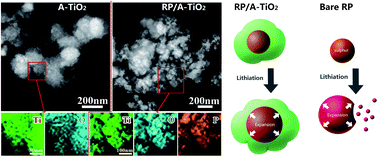
To verify the composition of A-TiO2 and RP/A-TiO2, scanning transmission electron microscope (STEM) and area-scan elemental mapping images are supplied. Fig. 4a–c present the morphology and elements distribution of A-TiO2. As seen in Fig. 4a, A-TiO2 exhibits rough surface, which is similar to the SEM results (Fig. 2f). Taken from red square area of A-TiO2 in Fig. 4a, the energy-dispersive spectroscopy (EDS) mappings demonstrate titanium element (Fig. 4b) and oxygen (Fig. 4c) element are dispersed homogeneously, implying the chemical composition of A-TiO2. The detailed microstructure and elements mappings of RP/A-TiO2 sample are showed in Fig. 4d–g. As seen in Fig. 4d, mapping square is selected in nanoparticles cluster area. Three elements of titanium (Fig. 4e), oxygen (Fig. 4f) and phosphorus (Fig. 4g) have the uniform distribution, suggesting the in situ formed A-TiO2 is tightly contacted with RP particles. These results also indicate that RP/A-TiO2 has the unique reinforced concrete structure.


image file: c4ra09836f-f4.tif
Fig. 4 (a) STEM image of A-TiO2; elemental mappings of titanium (b) and oxygen (c); (d) STEM image of RP/A-TiO2; elemental mappings of titanium (e), oxygen (f), and phosphorus (g).

Fig. 5 depicts the electrochemical performance of A-TiO2 and RP/A-TiO2. There is a pair of broad anodic/cathodic peaks in the CV curves of A-TiO2 (Fig. 5a), corresponding to the typical lithium insertion/extraction potential of A-TiO2.30 Compared with A-TiO2 sample, the broad redox potential of RP/A-TiO2 (Fig. 5b) is lower than A-TiO2. This result can be attributed to the electrode polarization since the RP has a much poorer electronic conductivity.31 Moreover, a small anodic peak at ∼2.4 V can be seen in the first two cycles, representing some irreversible process. As shown in Fig. 5c, the first discharge and charge capacities of A-TiO2 sample are 440 and 180 mA h g−1, respectively. The irreversible capacity loss reaches up to 260 mA h g−1. The sharply dropped capacity loss could be explained by the formation of solid electrolyte interface (SEI) layer32 and the reaction of H2O/–OH species adsorbed at the surface of sample.33 Meanwhile, the first discharge and charge capacities of RP/A-TiO2 sample are 770 and 450 mA h g−1, which has a larger irreversible capacity loss of 320 mA h g−1. This larger irreversible capacity loss compared with A-TiO2 could be related to the formation of SEI layer in RP component.25


image file: c4ra09836f-f5.tif
Fig. 5 (a and b) CV curves of A-TiO2 and RP/A-TiO2, respectively. (c and d) Discharge–charge profiles of A-TiO2 and RP/A-TiO2 with a current density of 100 mA g−1, respectively. (e) Cycling performances of A-TiO2 and RP/A-TiO2 with a current density of 100 mA g−1. (f) Rate performance of A-TiO2 and RP/A-TiO2 electrodes.

Fig. 5e presents the cycling performance of RP, A-TiO2, and RP/A-TiO2 samples. As seen in Fig. 5e, the capacity of bare RP sharply falls from 2222 to 143 mA h g−1 in the initial several cycles, and continually fall to 12 mA h g−1 at 30th cycle. That exhibits an extremely poor electrochemical performance. However, A-TiO2 and RP/A-TiO2 electrodes show the excellent cycling stability. The Coulombic efficiency of A-TiO2 and RP/A-TiO2 steadily reaches around 99% accompanied by the cycle number increasing. The discharge capacities of bare RP (30th), A-TiO2 (50th) and RP/A-TiO2 (100th) are 12, 157 and 369 mA h g−1, corresponding to 21.1, 93.4 and 89.3% capacity retentions of their initial discharge capacities (here we use the 3rd cycle data because the discharge capacity is becoming stable) of 57, 167 and 413 mA h g−1, respectively. It is note that the capacity retention of RP/A-TiO2 at 50th reaches to 92.3%, which is comparable with the A-TiO2 result of 93.4%. However, RP/A-TiO2 shows a much higher capacity retention of 369 mA h g−1 compared with bare RP and A-TiO2. Fig. 5f displays the rate performance of A-TiO2 and RP/A-TiO2 at various rates current densities. The discharge capacities of A-TiO2 and RP/A-TiO2 are reserved at 388/177, 336/141, 285/117, and 202/97 mA h g−1 at the current densities of 100, 200, 500 and 1000 mA g−1, respectively. It is noticed that the capacities at higher currents faded rapidly. However, when the current is restored to 100 mA g−1, A-TiO2 and RP/A-TiO2 both deliver the reversible capacity of 359 and 174 mA h g−1, respectively. This phenomenon is mainly due to the kinetic-limited effects of the electrochemical reaction in nature, rendering a higher over potential and a lower capacity at a higher current.34 Obviously, RP/A-TiO2 composite has a high reversible capacity and stable cycling performance that is mainly attributed to the unique with reinforced concrete structure. On the one hand, A-TiO2 stores lithium by addition-type reaction (xLi+ + TiO2 + xe → LixTiO2),30 which has a remarkable structural stability. It also can prevent the continuous capacity loss of RP derived from the crack and pulverization. On the other hand, RP has a large capacity in nature, which could provide more reversible capacity for the RP/A-TiO2 composite.

Since RP is extremely unstable during the Li+ insertion/extraction, we do the comparison of fresh and cycled RP/A-TiO2 electrode via STEM and area-scan elemental mapping tests to clarify the structural stability directly. Fig. 6a and f clearly present the STEM image of fresh RP/A-TiO2 electrode. Combining with elemental mapping analysis, P, Ti and O (Fig. 6b–d) are well dispersed in the acetylene black (Fig. 6e). For the cycled counterpart, the electrode was charged to 3 V (lithium extraction status) after 100 cycles. Elemental mappings in Fig. 6f–j reveal that the RP is distributed in the electrode as uniform as the fresh one. Fig. 6k illustrates the working principle of RP/A-TiO2 with reinforced concrete structure during the charge–discharge processes. When the expansion of inner RP occurs, the outer TiO2 cluster could buffer flexibly, preventing the RP running off. By effectively use the inner RP, 10 wt% RP could supply more than 200 mA h g−1 capacity in the composite, which render the double capacity comparing with A-TiO2.


image file: c4ra09836f-f6.tif
Fig. 6 (a) STEM image of RP/A-TiO2 electrode before cycling; (b–e) area-scan elemental mapping images of red square area in (a). (f) STEM image of RP/A-TiO2 electrode after cycling; (g–j) area-scan elemental mapping images of red square area in (f). (k) Schematic of lithiation process in bare RP and RP/A-TiO2.

4. Conclusions

In summary, a novel RP/A-TiO2 composite with the unique reinforced concrete structure was synthesized by in situ hydrolyzing on RP particles. RP and A-TiO2 play as the roles of “reinforced” and “concrete” respectively. Due to the synergistic effect of RP and A-TiO2, the as-prepared RP/A-TiO2 composite not only offers an enhanced reversible capacity, but also keeps the structural stability, presenting the remarkable electrochemical performance (369 mA h g−1, 100 cycles). Therefore, such a RP/A-TiO2 composite is a very promising anode material for advanced LIBs.

Acknowledgements

This work was supported by National Natural Science Foundation of China (51201151, 51172205 and 201403196), Natural Science Foundation of Zhejiang Province (LR13E020002 and LY13E020010), Scientific Research Foundation of Zhejiang Provincial Education Department (Y201432424) and New Century Excellent Talents in University (NCET 111079).

Notes and references

  1. V. Etacheri, J. E. Yourey and B. M. Bartlett, ACS Nano, 2014, 8, 1491–1499 CrossRef CAS PubMed.
  2. R. W. Mo, Z. Y. Lei, K. N. Sun and D. Rooney, Adv. Mater., 2014, 26, 2084–2088 CrossRef CAS PubMed.
  3. A. Attia, Q. Wang, X. K. Huang and Y. Yang, J. Solid State Electrochem., 2012, 16, 1461–1471 CrossRef CAS PubMed.
  4. M. Armand and J. M. Tarascon, Nature, 2008, 451, 652–657 CrossRef CAS PubMed.
  5. B. Kang and G. Ceder, Nature, 2009, 458, 190–193 CrossRef CAS PubMed.
  6. A. S. Arico, P. Bruce, B. Scrosati, J. M. Tarascon and W. Van Schalkwijk, Nat. Mater., 2005, 4, 366–377 CrossRef CAS PubMed.
  7. H. Huang, W. J. Zhu, X. Y. Tao, Y. Xia, Z. Y. Yu, J. W. Fang, Y. P. Gan and W. K. Zhang, ACS Appl. Mater. Interfaces, 2012, 4, 5974–5980 CAS.
  8. X. Y. Tao, J. T. Zhang, Y. Xia, H. Huang, J. Du, H. Xiao, W. K. Zhang and Y. P. Gan, J. Mater. Chem. A, 2014, 2, 2290–2296 CAS.
  9. Y. Xia, W. K. Zhang, Z. Xiao, H. Huang, H. J. Zeng, X. R. Chen, F. Chen, Y. P. Gan and X. Y. Tao, J. Mater. Chem., 2012, 22, 9209–9215 RSC.
  10. S. B. Yang, X. L. Feng, S. Ivanovici and K. Mullen, Angew. Chem., Int. Ed., 2010, 49, 8408–8411 CrossRef CAS PubMed.
  11. H. Huang, J. W. Fang, Y. Xia, X. Y. Tao, Y. P. Gan, J. Du, W. J. Zhu and W. K. Zhang, J. Mater. Chem. A, 2013, 1, 2495–2500 CAS.
  12. X. Zhang, H. X. Chen, Y. P. Xie and J. X. Guo, J. Mater. Chem. A, 2014, 2, 3912–3918 CAS.
  13. S. H. Choi, J. H. Lee and Y. C. Kang, Nanoscale, 2013, 5, 12645–12650 RSC.
  14. H. T. Fang, M. Liu, D. W. Wang, T. Sun, D. S. Guan, F. Li, J. G. Zhou, T. K. Sham and H. M. Cheng, Nanotechnology, 2009, 20, 225701 CrossRef PubMed.
  15. J. S. Chen, D. Y. Luan, C. M. Li, F. Y. C. Boey, S. Z. Qiao and X. W. Lou, Chem. Commun., 2010, 46, 8252–8254 RSC.
  16. Y. P. Tang, D. Q. Wu, S. Chen, F. Zhang, J. P. Jia and X. L. Feng, Energy Environ. Sci., 2013, 6, 2447–2451 CAS.
  17. X. Y. Li, Y. M. Chen, L. M. Zhou, Y. W. Mai and H. T. Huang, J. Mater. Chem. A, 2014, 2, 3875–3880 CAS.
  18. L. Yu, Z. Y. Wang, L. Zhang, H. B. Wu and X. W. Lou, J. Mater. Chem. A, 2013, 1, 122–127 CAS.
  19. D. S. Guan, J. Y. Li, X. F. Gao and C. Yuan, J. Power Sources, 2014, 246, 305–312 CrossRef CAS PubMed.
  20. C. M. Ban, M. Xie, X. Sun, J. J. Travis, G. K. Wang, H. T. Sun, A. C. Dillon, J. Lian and S. M. George, Nanotechnology, 2013, 24, 424002 CrossRef PubMed.
  21. J. F. Qian, D. Qiao, X. P. Ai, Y. L. Cao and H. X. Yang, Chem. Commun., 2012, 48, 8931–8933 RSC.
  22. L. Q. Sun, M. J. Li, K. Sun, S. H. Yu, R. S. Wang and H. M. Xie, J. Phys. Chem. C, 2012, 116, 14772–14779 CAS.
  23. M. Nagao, A. Hayashi and M. Tatsumisago, J. Power Sources, 2011, 196, 6902–6905 CrossRef CAS PubMed.
  24. C. M. Park and H. J. Sohn, Adv. Mater., 2007, 19, 2465–2468 CrossRef CAS.
  25. L. Wang, X. M. He, J. J. Li, W. T. Sun, J. Gao, J. W. Guo and C. Y. Jiang, Angew. Chem., Int. Ed., 2012, 51, 9034–9037 CrossRef CAS PubMed.
  26. Y. Kim, Y. Park, A. Choi, N. S. Choi, J. Kim, J. Lee, J. H. Ryu, S. M. Oh and K. T. Lee, Adv. Mater., 2013, 25, 3045–3049 CrossRef CAS PubMed.
  27. X. F. Wang and L. Andrews, J. Phys. Chem. A, 2005, 109, 10689–10701 CrossRef CAS PubMed.
  28. Z. Liu, Z. C. Jian, J. Z. Fang, X. X. Xu, X. M. Zhu and S. X. Wu, Int. J. Photoenergy, 2012, 2012, 702503 Search PubMed.
  29. J. Fang, F. Wang, K. Qian, H. Z. Bao, Z. Q. Jiang and W. X. Huang, J. Phys. Chem. C, 2008, 112, 18150–18156 CAS.
  30. Y. M. Lin, P. R. Abel, D. W. Flaherty, J. Wu, K. J. Stevenson, A. Heller and C. B. Mullins, J. Phys. Chem. C, 2011, 115, 2585–2591 CAS.
  31. G. Jeong, J. H. Kim, Y. U. Kim and Y. J. Kim, J. Mater. Chem., 2012, 22, 7999–8004 RSC.
  32. C. Marino, L. Boulet, P. Gaveau, B. Fraisse and L. Monconduit, J. Mater. Chem., 2012, 22, 22713–22720 RSC.
  33. W. J. H. Borghols, D. Lutzenkirchen-Hecht, U. Haake, W. Chan, U. Lafont, E. M. Kelder, E. R. H. van Eck, A. P. M. Kentgens, F. M. Mulder and M. Wagemaker, J. Electrochem. Soc., 2010, 157, A582–A588 CrossRef CAS PubMed.
  34. Y. Xia, Z. Xiao, X. Dou, H. Huang, X. H. Lu, R. J. Yan, Y. P. Gan, W. J. Zhu, J. P. Tu, W. K. Zhang and X. Y. Tao, ACS Nano, 2013, 7, 7083–7092 CrossRef CAS PubMed.

This journal is © The Royal Society of Chemistry 2014