Studies on FMCM-41 reinforced cyanate ester nanocomposites for low k applications

Mathivathanan Ariraman, Ramachandran Sasi kumar and Muthukaruppan Alagar*
Polymer Composites Lab, Department of Chemical Engineering, A. C. Tech, Anna University, Chennai-600 025, India. E-mail: mkalagar@yahoo.com

Received 28th August 2014 , Accepted 20th October 2014

First published on 20th October 2014


Abstract

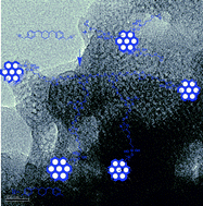
The continual development of microelectronics needs insulation materials with lower dielectric constant (low k). To accomplish this, a new type of cyclohexyl branched aliphatic chain bridged cyanate ester has been developed by the synthesis of chalcone from 4-hydroxybenzaldehyde and cyclohexanone, and followed by reduction. Cyanate ester nanocomposites have been developed by polymerizing cyanate ester monomer reinforced with varying weight percentages of glycidyl silane functionalized mesoporous MCM-41 (FMCM-41). Subsequently, the monomer and polymer composites were characterized by spectral analysis using FTIR (Fourier transform infrared), 1H and 13C NMR (nuclear magnetic resonance) spectroscopy. The thermal properties were analyzed by TGA (thermogravimetric analysis) and DSC (differential scanning calorimetry), and morphological studies were carried out by SEM (scanning electron microscopy) and HRTEM (high resolution transmission electron microscopy). The HRTEM images clearly indicate the existence of pores, which were responsible for the reduction of the dielectric constant. The dielectric properties were measured by broadband dielectric spectrometer. From the dielectric studies it was inferred that 10 wt% of MCM-41 reinforced BCC polymer composites exhibits the lowest value of dielectric constant of 1.98 at 1 MHz.

Introduction

The microelectronics industries are continuously trying to find new technological solutions to the reduction of resistance–capacitance (RC) time delay, power consumption, and ‘cross-talk’ between nearby interconnects, and to keep pace with the trend of increasing device densities in ultra-large-scale integrated (ULSI) circuits.1 Generally, microelectronic integrated circuits consist of interconnected wires which are insulated by dielectric materials with intra and interlayer capacitance.2 In order to reduce the capacitance, it is essential to replace the present insulating materials with the introduction of thin films of low dielectric materials (<2.2).3 There are two main routes normally used to reduce the dielectric constant: (1) by the preparation of polymer nanocomposites with porous silica materials such as polyhedraloligomericsilsesquioxane (POSS),4 SBA-15,5 MCM-41,6 etc., and (2) by the introduction of less polar aliphatic groups into the skeleton.4 Thus, the incorporation of porous materials into the polymers significantly reduces the dielectric constant of the polymer composites because the intrinsic air/vacuum has a dielectric constant of ∼1.7 Subsequently, thermally stable dense silica materials drastically increase the thermal stability of the polymer composites. In addition, the existence of less polar functional groups strongly reduces the dielectric constant of the matrix due to the reduction of polarization throughout the matrix which in turn results in lowering the capacitance between the electrodes.8 The ratio of the permittivity of a substance to that of free space is called the dielectric constant (k) or relative permittivity (εr). A material containing non-polar components has less electric dipoles (e.g. non polar chemical bonds) and a decreased dielectric constant. The dipole formation is a result of electronic polarization (displacement of electrons), distortion polarization (displacement of ions), or orientation polarization (displacement of molecules) in an alternating electric field. These phenomena have characteristic dependencies on the frequency of the alternating electric field, giving rise to a change in the real and imaginary part of the dielectric constant between the microwave, ultraviolet, and optical frequency range.1,9 The less polar aliphatic chains inherently reduce the dipoles between the electrodes and significantly reduce the value of the dielectric constant.

Networked polymer matrices such as polyimide,10 polybenzoxazine,5 PEEK,11 and cyanate ester3 have frequently been reported as low k materials. Among these the cyanate ester (CE) resin systems have drawn increasing attention due to their unique properties such as good thermal and mechanical properties, high glass transition temperature (Tg), radiation resistance, excellent metal adhesion, compatibility with carbon fiber reinforcements, high flame retardant, low moisture uptake and excellent electrical insulation behavior.12 Moreover, these outstanding performances of CE resin make them an excellent material for radiation resistant and high temperature applications in aerospace, as adhesives, and as sealants for microelectronics.13 A cyanate ester resin is a class of thermosetting polymers and can be prepared by the thermal treatment of a monomer in the absence of any catalyst. It is well known that the cyanate esters can easily combined with epoxy resin through covalent bond to form oxazoline five membered rings with low curing temperature. It can also be self-polymerized to obtain cross linked polycyanurate with six member triazine rings.14 The polycyanurate segment contributes to improved thermal stability and superior mechanical toughness to other thermosetting polymers. Furthermore, the existence of less polar aliphatic, oxazoline, and triazine influence the reduction of the value of the dielectric constant of the materials. Recently, porous silica materials incorporated into cyanate ester polymer nanocomposites have been reported, and it can be seen that the 10% OG-POSS reinforced bisphenol cyanate ester nanocomposites exhibit the value of dielectric constant of 2.4 which is lower than that of neat CE matrix.8 In addition, 15% glycidyl silane functionalized mesoporous silica reinforced polycyanurate exhibits a lower value of dielectric constant (2.11) than that of neat matrix.3 Hence, reinforcing the varying weight percentages of porous silica and the existence of less polar aliphatic long chains in the polymer composites are vital parameters considered to reduce the dielectric behavior of insulating materials.

In this context, in the present work we have developed a cyclohexyl branched aliphatic long chain bridged phenolic cyanate ester which was cured and reinforced with varying weight percentages of glycidyl silane functionalized mesoporous MCM-41 and then characterized and reported. It was observed that increasing weight percentages of FMCM-41 strongly influenced the reduction of the value of the dielectric constant and also significantly enhanced the thermal stability of the cyanate ester polymer nanocomposites.

Experimental

Materials

Analytical grades of 4-hydroxybenzaldehyde, cyclohexanone, cyanogen bromide (CNBr), triethyl amine (TEA), acetic acid, sulfuric acid and solvents were purchased from SRL, India. High purity sodium trisilicate, cetyl trimethylammonium bromide (CTAB), 3-(glycidyloxypropyl)trimethoxysilane (GPTMS) and 10% Pd/C were purchased from Sigma-Aldrich and were used as received without further purification.

Synthesis of (2E,6E)-2,6-bis(4-hydroxybenzylidene)cyclohexanone (BHC)

(2E,6E)-2,6-Bis(4-hydroxybenzylidene)cyclohexanone (BHC) was synthesized as per the reported procedure.15 To a solution of 4-hydroxybenzaldehyde in a mixture of acetic acid and a catalytic amount of sulfuric acid, cyclohexanone was added and stirred for 48 h at room temperature. After the completion of the reaction (monitored by TLC), ice cold water was added to the reaction mixture and the resulting precipitate was filtered and washed several times with water to yield 90% off brown solid as the final product.

Synthesis of 4,4′-(cyclohexane-1,3-diylbis(methylene))diphenol (CDD)

To a stirred solution of BHC in methanol, 10% Pd/C was added under N2 atmosphere and the reaction atmosphere was subsequently changed to hydrogen and stirred for 48 h at RT. After the completion of the reaction, the reaction mixture was filtered through celite and the filtrate was concentrated under reduced pressure. The purification procedure is as follows: the resulting product was dissolved with a small amount of methanol and cooled with crushed ice, followed by the addition of cold water to obtain the precipitate. The precipitate was filtered and washed several times with water and dried for 12 h at 70 °C to yield 90% pale pink solid product.
1H NMR (DMSO-d6, δ, ppm). 9.14 (–OH), 6.93–6.61 (aromatic protons), 2.63–2.46 (methylene proton), 1.89–1.16 (cycloaliphatic protons).

Synthesis of 1,3-bis(4-cyanatobenzyl) cyclohexane (BCC)

The synthesis of 1,3-bis(4-cyanatobenzyl) cyclohexane (BCC) is as follows: CDD was dissolved in dry acetone under nitrogen atmosphere and then the solution of cyanogen bromide in acetone was added, followed by the slow addition of triethyl amine at −15 °C. Then the temperature was slowly raised to room temperature and stirred for 1 h. Subsequently, the reaction mixture was filtered and the filtrate was added to cold water, the precipitate thus obtained was filtered and washed several times with water and dried for 12 h at 40 °C to yield 88% pale yellow solid product.
FTIR (KBr cm−1). 2923 (symmetric stretching), 2854 (cyclohexyl CH2 asymmetric stretching), 2238 (CN vibration stretching).
1H NMR (DMSO-d6, δ, ppm). 7.45–7.33 (aromatic protons), 2.49–2.39 (methylene protons), 1.65–1.20 (cycloaliphatic protons).
13C NMR (DMSO-d6, δ, ppm). 150.91, 139.78, 131.28, 115.26 (aromatic carbon), 108.98 (OCN), 51.32 (methylene carbon) 34.15, 26.02, 24.44 (cycloaliphatic carbon).

Synthesis of MCM-41 and functionalization of MCM-41 (FMCM-41)

MCM-41 was synthesized as per the previous report16,17 as follows: to an aqueous solution of sodium trisilicate, catalytic amount of cetyl trimethylammonium bromide (CTAB) was added drop by drop at room temperature under vigorous stirring and continued for 1 h. Then the resultant gel was heated for 24 h at 100 °C. The jelly mass was cooled to room temperature, and the pH was adjusted to 10 with acetic acid and it was further heated for 48 h at 100 °C. The pH adjustment and subsequent heating were repeated, and the precipitated MCM-41 product was collected by filtration. The product was washed with ethanol and calcined in air at 550 °C. After that, MCM-41 was functionalized with GPTMS (FMCM-41) as per the procedure reported;18 to a suspended solution of MCM-41 in ethanol, GPTMS was added and sonicated for 1 h and then the mixture was refluxed for 24 h. After that the precipitate was filtered and washed with cold ethanol and dried at 70 °C under reduced vacuum to obtain FMCM-41.

Development of BCC/FMCM-41 nanocomposites

The BCC/FMCM-41 nanocomposites with different concentrations of FMCM-41 (1, 3, 5, 7 and 10%) were prepared according to Scheme 2; the solution of FMCM-41 in THF was sonicated for 15 minutes, and subsequently BCC was added to that clear solution and stirred for 15 minutes at 30 °C. The resulting viscous solution was poured into a respective glass mold and allowed to evaporate the solvent at 50 °C for 3 h and then the temperature was raised slowly to 210 °C at a heating rate of 20 °C h−1. After that the cured films were removed and preserved for further characterization.

Characterization

FTIR spectroscopic measurements were conducted on a Bruker TENSOR 27 using KBr pellet method. 1H and 13C NMR spectra were recorded on a Bruker 500 NMR spectrometer. Thermogravimetric measurements were carried out on a Q500 Hi-Res TGA thermogravimetric analyzer from TA instruments. The samples (about 10 mg) were heated from ambient temperature to 800 °C under a continuous flow of nitrogen (20 mL min−1), at a heating rate of 10 °C min−1. The calorimetric analysis of the nanocomposites was performed on a Netzsch DSC-200 differential scanning calorimeter at a heating rate of 10 °C min−1 under nitrogen atmosphere. The X-ray photoelectron spectroscopic analysis of the samples was carried out using a JEOL JPS-9200 photoelectron spectrometer with a monochromatized Al-Kα X-ray source operated at 12 kV and 20 mA.

High resolution transmission electron microscope (HRTEM) analysis was carried out on a TECNAI-G2 (model T-30) at an accelerating voltage of 300 kV. Scanning electron microscope (SEM) measurements were performed using a VEGA 3 TESCAN scanning electron microscope. The piece of film was fixed to the surface of double-sided adhesive tape, and the film was sputtered with gold prior to SEM observation. Dielectric constant was determined by Broadband Dielectric Spectrometer (BDS), NOVOCONTROL Technologies GmbH & Co. (model Concept 80) at 30 °C in the range of 100 Hz to 1 MHz.

Results and discussion

To investigate the dielectric properties of cyanate ester matrices and composites (Scheme 2), a less polar aliphatic based cyanate ester was designed and its molecular structure was confirmed by NMR and FTIR spectral analysis. For the synthesis of BCC, a three-step process was used; first BHC was synthesized and then the BHC was reduced to get cyclohexyl branched aliphatic chain bridged phenolic diol (CDD). Finally, CDD was treated with cyanogen bromide to get BCC (Scheme 1). Fig. 1a presents the 1H NMR spectral data for CDD. The appearance of peaks at 9.14 ppm was attributed to the aromatic OH group and the peaks in the range from 6.93 to 6.61 ppm correspond to the aromatic protons. The formation of cyclohexane branched aliphatic chain linked aromatic diol was confirmed by the appearance of peaks in the range from 2.63 to 2.46 ppm and 1.89 to 1.16 ppm, which represent the aliphatic shielded region. Further, the successful formation of cyanate ester was confirmed by FTIR, 1H and 13C NMR spectral data. Fig. 1b shows the 1H NMR spectra, the disappearance of the respective aromatic OH peak and the retaining of peaks in the ranges from 7.45–7.33 ppm (aromatic protons), 2.49–2.39 ppm (methylene protons) and 1.65–1.20 ppm (cycloaliphatic protons) indicate the formation of cyanate ester. Furthermore, the structure elucidation was also confirmed by 13C NMR (Fig. 1c); the peak at 108.9 was associated with OCN and also the aromatic and aliphatic peaks exhibit in the ranges of 150.91 to 139.8 ppm and 51.3 to 24.4 ppm, respectively. In addition, the FTIR spectral data (Fig. 1d) was also used to ascertain the OCN formation; the new absorption band at 2238 cm−1 was attributed to OCN and the respective aliphatic vibration bands were observed in the range of 2854 to 2923 cm−1 indicating the successful formation of BCC.
image file: c4ra09399b-s1.tif
Scheme 1 Preparation of BCC cyanate ester.

image file: c4ra09399b-s2.tif
Scheme 2 Preparation of BCC/FMCM-41 polymeric nanocomposites.

image file: c4ra09399b-f1.tif
Fig. 1 (a) 1H NMR spectrum of CDD, (b) 1H NMR spectrum of BCC, (c) 13C NMR spectrum of BCC and (d) FTIR spectrum of BCC monomer.

The molecular structures of MCM-41 and FMCM-41 were confirmed by FTIR spectra (Fig. 2). FTIR spectra show the bands at 1087 cm−1 and 792 cm−1 which correspond to the asymmetric and symmetric stretching vibrations of the Si–O–Si bond, respectively. The broad absorption band at 3500 cm−1 was attributed to the hydroxyl group of MCM-41. In addition, the GPTMS functionalized FMCM-41 was confirmed by the appearance of new bands at 2933 cm−1 and 2856 cm−1 representing the asymmetric and symmetric stretching modes of the CH2 group, respectively, and the band appearing at 934 cm−1 indicates the presence of a glycidyl group, which confirms the successful functionalization of FMCM-41.


image file: c4ra09399b-f2.tif
Fig. 2 FTIR spectra of MCM-41 and GPTMS functionalized FMCM-41.

The cured BCC/FMCM-41 nanocomposites were characterized by FTIR spectra. Fig. S1 shows the disappearance of bands at 2252 cm−1 (the –OCN group of the cyanate ester) and 943 cm−1 (the glycidyl group of FMCM-41) and the appearance of a band at 1645 cm−1 (oxazoline ring) indicates the successful incorporation of FMCM-41 through covalent bonding by cyclic oxazoline ring formation between the OCN group of the cyanate ester and the glycidyl group of FMCM-41. Further, the appearance of bands at 1085 cm−1 and 1365 cm−1 are associated with Si–O–Si linkages and the triazine ring, respectively,3 which indicates the successful formation of triazine rings by the self-polymerization of OCN. The combination of triazine and oxazoline rings with aliphatic chain and porous silica materials facilitates the reduction of the dielectric constant of the nanocomposites.

The various chemical bonds of polymer nanocomposites have their own binding energies and can be evaluated by X-ray photoelectron spectroscopy (XPS), from which the formations of the chemical structures of the polymer composites were examined. Fig. 3a shows the XPS survey spectra of BCC/10% FMCM-41, from which it could be clearly observed that the binding energies of elemental peaks at 283 eV, 531 eV, 398 eV, and 101 eV correspond to C1s, O1s, N1s, and Si2p, respectively.19,20 Fig. 3b–d shows the deconvolution peaks of individual elements with the characteristic binding energies and is supported by earlier reports. Consequently, the deconvoluted peaks infer the existence of different kinds of bonds in the polymer composites with typical binding energies. Fig. 3b shows the deconvolution of the C1s signal into three peaks; the major peak at 284.4 eV corresponds to C–C, C[double bond, length as m-dash]C and Si–C bonds and the second major peak at 285.6 eV is associated to the C–O–C bonds. Subsequently, the third peak at 288.6 eV represents N[double bond, length as m-dash]C–O bonds of the oxazoline ring indicating the successful incorporation of FMCM-41 through covalent bonds.21 Fig. 3c shows the deconvolution of the N1s signal into two peaks; the peak at 398.4 eV was assigned to the contribution of the C[double bond, length as m-dash]N–C bonds of triazine ring in the polymer composites, implying that the cyanate esters were self-polymerized to form polycyanurate, and the peak at 404.5 eV represents the characteristic shake up satellite peak which was raised by π–π* transitions in the aromatic groups.22 In addition, the characteristic O1s signal was deconvoluted into two peaks; the major peak (Fig. 3d) at 530.9 eV corresponds to C–O and the other one exhibited at 532.2 eV was assigned to the Si–O–Si bonds. From these observations the successful formation of BCC/FMCM-41 polymer nanocomposites through strong covalent bonds could be clearly ascertained.


image file: c4ra09399b-f3.tif
Fig. 3 XPS spectra of BCC/10% FMCM-41 polymeric nanocomposites.

The well-defined surface microstructure of the polymer nanocomposites can be observed by scanning electron microscopy (SEM). Fig. 4 shows the SEM images of the surface of the neat and 10% FMCM-41 reinforced cyanate ester composites, from which it could be clearly observed that the smooth surface indicates the homogeneous polymerization of cyanate ester. The homogeneous distribution of light spots in the BCC/FMCM-41 polymer composites indicates the covalently bonded FMCM-41 with the cyanate ester through the oxazoline ring and influences the formation of a homogeneous surface. Fig. 4c describes the results of Si-mapping of the 10% FMCM-41 composite and demonstrates the uniform distribution of MCM-41 over the surface. Thus, the distinguishable microstructures of neat and their composites indicate the existence of silica particles well coordinated with cyanate esters in their composites which could contribute to sustainable thermal stability. However, the dielectric features of the polymer composite films could not be described and the internal microstructure of the films needs to be studied.


image file: c4ra09399b-f4.tif
Fig. 4 SEM images of (a) BCC polymer and (b) BCC/10% FMCM-41, and (c) Si mapping of BCC/10% FMCM-41 polymeric nanocomposite.

In order to understand the internal microstructure of the composites with varying weight percentages of FMCM-41, they were studied by high resolution transmission electron microscope (HRTEM). Fig. 5a and b and 5c and d shows the HRTEM images of MCM-41 and BCC/10% FMCM-41 composites, respectively. Fig. 5a and b shows the porous nature of the as prepared MCM-41 materials. Subsequently, the different weight percentages of FMCM-41 were incorporated into the cyanate ester resin to form cyanate ester nanocomposites. From Fig. 5c and d it can be seen that the porous silica nanoparticles are surrounded by cyanate ester with distinct distances. In addition, the uniform distribution of the porous silica segments in the composites provides an ordered air/vacuum in the appropriate places. Thus, the definite internal microstructure clearly demonstrates the existence of pores which contributes to the reduction in the value of the dielectric constant of the composites.


image file: c4ra09399b-f5.tif
Fig. 5 HRTEM images of (a and b) MCM-41 and (c and d) BCC/10% FMCM-41 polymeric nanocomposites.

The thermal stability of the BCC/FMCM-41 composites has been ascertained by thermogravimetric analysis. Fig. 6 shows the TGA curve of different weight ratios of BCC/FMCM-41 composites. It can be seen that the increasing weight percentages of FMCM-41 increases the thermal stability of the resulting polymer composites and the highest percentage of 10% mesoporous silica exhibits better thermal stability than the neat sample indicating that the existence of rigid siloxane and the strong covalent bond of the Si–O–Si skeleton contribute to the enhanced thermal stability of the composites. In addition, the gradual increment of char yield suggests that the presence of the triazine ring and oxazoline linked silica materials convert to form a thermally stable rigid graphene like structure with silica layers at higher temperature.23 In detail, the initial weight loss of material below 200 °C is probably due to the removal of residual solvent and adsorbed moisture. The major weight loss observed above 300 °C is associated with the decomposition of the polymer network and finally to yield residual chair at 800 °C; these are presented in Table 1. Moreover, the higher decomposition temperature and char yield indicate the higher thermal stability of the polymer composites, which suggests the utility of these composites in the field of microelectronics as interlayer materials. Fig. S2 shows the DSC profiles of neat BCC and BCC/10% FMCM-41 composites. The neat BCC exhibits a broad exothermic peak maximum at 210 °C indicating the formation of polycyanurate by the polymerisation of cyanate ester which is an exothermic reaction. The BCC/10% FMCM-41 shows the absence of an exothermic peak indicating the occurrence of completely polymerised composites. The existence of absolute polymerisation illustrates the uniform structure formation.


image file: c4ra09399b-f6.tif
Fig. 6 Thermogram curve BCC/FMCM-41 polymeric nanocomposites.
Table 1 Thermal and dielectric properties of BCC/FMCM-41 nanocomposites
Sample Char yield 800 °C (%) Dielectric constant Tangent loss
BCC 14.88 2.97 0.0233
BCC/1% FMCM-41 16.18 2.87 0.0103
BCC/3% FMCM-41 16.94 2.58 0.0102
BCC/5% FMCM-41 21.49 2.22 0.0102
BCC/7% FMCM-41 23.6 2.08 0.0092
BCC/10% FMCM-41 25.55 1.98 0.0140


Microelectronics devices need a lower dielectric constant material as an interlayer, so it warrants the development of such novel materials. Recently, researchers have made many efforts towards the reduction of the dielectric constant of polymeric materials due to their characteristic physico chemical properties. Thus, the materials with the lowest dielectric constant (below 2) have potential applications in electronic devices. In order to obtain the potential dielectrics, porous silica based polycyanurate polymer composites were prepared by the polymerization of cyanate ester with varying weight percentages of mesoporous materials. Fig. 7, S3 and Table 1 show the dielectric constant (k) and dielectric loss of the neat and composite materials. Fig. 7 shows the decreasing trend of dielectric constant with increasing FMCM-41 content due to the increasingly porous nature of the silica material which provokes air in the composites. Fig. 8 presents the log–log form of the frequency dependency of the dielectric constant for BCC/FMCM-41 nanocomposites. From Fig. 8 the significant variation on dielectric constant with the frequency as well as FMCM-41 concentration can be seen. The absence of peaks (Fig. 8) indicates the homogeneous polarization of the nanocomposites. Over the measured frequency region, plateau variation in dielectric constant was observed in both the lower and higher frequency regions which demonstrates that low relaxation and less interfacial polarization of the matrix.24,25 In addition, the HRTEM images clearly show the existence of pores, which suggests that the existing pores mainly contribute to the reduction of the dielectric constant of the material. The neat polycyanurate exhibits a dielectric constant of 2.98 which is a lower value than that of the previously reported polycyanurate. This may be due to the presence of a greater number of less polarizable aliphatic CH2 groups in the polymer composites. Moreover, the non-polar aliphatic chain intrinsically reduces the dipoles between the electrodes and significantly reduces the dielectric constant throughout the matrix, because the reduction of polarization between the electrodes influences the reduction of capacitance and hence reduces the dielectric constant. In addition, the increase in weight percentages of FMCM-41 lowers the value of dielectric constant upto 10 wt%. Beyond 10 wt% the reverse trend was noticed, due to agglomeration of FMCM-41 in the matrix system (Table 1). The dielectric loss is one the most important factors in interlayer dielectrics which could contribute to power consumption in microelectronics. Moreover, the lowest value of dielectric loss mainly contributes to the reduction of current leakages and avoiding cross talk. Fig. S3 shows the dielectric loss spectrum of neat and varying weight percentages of FMCM-41. The neat polycyanurate exhibits the tangent loss value of 0.0233 and the lowest tangent loss value of 0.0092 was observed for BCC/7% FMCM-41 polymer nanocomposites indicating that these types of composite materials can be employed as a potential candidates for next generation microelectronics.


image file: c4ra09399b-f7.tif
Fig. 7 Dielectric constants of BCC and BCC/FMCM-41 polymeric nanocomposites.

image file: c4ra09399b-f8.tif
Fig. 8 Log–log plot dielectric constants of BCC and BCC/FMCM-41 polymeric nanocomposites.

Conclusion

With a view to reducing the dielectric constant, a new class of cyclohexyl branched aliphatic chain bridged phenolic cyanate ester has been synthesized and subsequently polycyanurate composites with varying weight percentages of glycidyl silane functionalized MCM-41 were developed. The existence of less polar aliphatic groups in the cyanate ester monomer skeleton significantly reduced the value of the dielectric constant in the neat polycyanurate; however, it is not sufficient to meet the low k requirements. Hence, it was further reduced by the incorporation of mesoporous functionalized FMCM-41; the homogeneously dispersed composites of BCC/10% FMCM-41 exhibit the lowest value of dielectric constant of 1.98 at 1 MHz. In addition, the dielectric loss was also decreased with increasing mesoporous FMCM-41 content. Further the thermal stability of polymer composites was also considerably increased with increasing Si–O–Si linkage. Data resulting from different experimental studies suggests that the newly developed class of skeletal modified cyanate ester polymer composites can be used as a potential insulation material for microelectronic applications.

Acknowledgements

The authors thank DST (Nanomission), SR/NM/NS-18/2010, New Delhi, Govt. of India, for the financial support. The authors also thank Dr K. Gunasekaran, and Mr M. Kesavan, Department of Crystallography and Biophysics for providing the NMR facility and Dr S. Balakumar, National Centre for Nanoscience and Nanotechnology, University of Madras, for providing the HRTEM facility.

References

  1. B. D. Hatton, K. Landskron, W. J. Hunks, M. R. Bennett, D. Shukaris, D. D. Perovic and G. A. Ozin, Mater. Today, 2006, 9, 22–31 CrossRef CAS.
  2. R. D. Miller, Science, 1999, 286, 421–423 CrossRef CAS.
  3. S. Devaraju, M. R. Vengatesan, M. Selvi, J. K. Song and M. Alagar, Microporous Mesoporous Mater., 2013, 179, 157–164 CrossRef CAS PubMed.
  4. R. Sasi kumar, M. Ariraman and M. Alagar, RSC Adv., 2014, 4, 19127–19136 RSC.
  5. M. R. Vengatesan, S. Devaraju, K. Dinakaran and M. Alagar, J. Mater. Chem., 2012, 22, 7559–7566 RSC.
  6. S. Baskaran, J. Liu, K. Domansky, N. Kohler, X. Li, C. Coyle, G. E. Fryxell, S. Thevuthasan and R. E. Williford, Adv. Mater., 2000, 12, 291–294 CrossRef CAS.
  7. F. Goethals, I. Ciofi, O. Madia, K. Vanstreels, M. R. Baklanov, C. Detavernier, P. Van Der Voorta and I. Van Driessche, J. Mater. Chem., 2012, 22, 8281–8286 RSC.
  8. S. Devaraju, P. Prabunathan, M. Selvi and M. Alagar, Front. Chem., 2013, 1, 1–10 Search PubMed.
  9. D. Shamiryan, T. Abell, F. Iacopi and K. Maex, Mater. Today, 2004, 7, 34–39 CrossRef CAS.
  10. E. Aram and S. Mehdipour-Ataei, J. Appl. Polym. Sci., 2013, 128, 4387–4394 CrossRef CAS.
  11. Z. Geng, M. Huo, J. Mu, S. Zhang, Y. Lu, J. Luan, P. Huo, Y. Dua and G. Wang, J. Mater. Chem. C, 2014, 2, 1094–1103 RSC.
  12. B. Yameen, H. Duran, A. Best, U. Jonas, M. Steinhart and W. Knoll, Macromol. Chem. Phys., 2008, 209, 1673–1685 CrossRef CAS.
  13. M. Laskoski, D. D. Dominguez and T. M. Keller, Polymer, 2006, 47, 3727–3733 CrossRef CAS PubMed.
  14. G. Zhan, L. Zhao, S. Hu, W. Gan, Y. Yu and X. Tang, Polym. Eng. Sci., 2008, 48, 1322–1328 CAS.
  15. X. Fang, L. Fang, S. Gou and L. Cheng, Bioorg. Med. Chem. Lett., 2013, 23, 1297–1301 CrossRef CAS PubMed.
  16. Z. Liu, Y. Sakamoto, T. Ohsuna, K. Hiraga, O. Terasaki, C. H. Ko, H. J. Shin and R. Ryoo, Angew. Chem., 2000, 112, 3237–3240 CrossRef.
  17. A. Kalilur Rahiman, K. Shanmuga Bharathi, S. Sreedaran, K. Rajesh and V. Narayanan, Inorg. Chim. Acta, 2009, 362, 1810–1818 CrossRef CAS PubMed.
  18. M. R. Mello, D. Phanon, G. Q. Silveira, P. L. Llewellyn and C. M. Ronconi, Microporous Mesoporous Mater., 2011, 143, 174–179 CrossRef CAS PubMed.
  19. L. Zhang, A. Chatterjee, M. Ebrahimi and K. T. Leung, J. Chem. Phys., 2009, 130, 121103 CrossRef CAS PubMed.
  20. K. Ellinas, S. P. Pujari, D. A. Dragatogiannis, C. A. Charitidis, A. Tserepi, H. Zuilhof and E. Gogolides, ACS Appl. Mater. Interfaces, 2014, 6, 6510–6524 CAS.
  21. E. S. Kim, G. Hwang, M. G. El-Din and Y. Liu, J. Membr. Sci., 2012, 394–395, 37–48 CrossRef CAS PubMed.
  22. A. P. Dementjev, A. de Graaf, M. C. M. van de Sanden, K. I. Maslakov, A. V. Naumkin and A. A. Serov, Diamond Relat. Mater., 2009, 9, 1904–1907 CrossRef.
  23. R. E. Lyon, R. N. Walters and S. Gandhi, Fire Mater., 2006, 30, 89–106 CrossRef CAS.
  24. M. Ariraman, R. Sasi kumar and M. Alagar, J. Appl. Polym. Sci., 2014, 131, 41097 CrossRef.
  25. R. Popielarz, C. K. Chiang, R. Nozaki and J. Obrzut, Macromolecules, 2001, 34, 5910–5915 CrossRef CAS.

Footnote

Electronic supplementary information (ESI) available. See DOI: 10.1039/c4ra09399b

This journal is © The Royal Society of Chemistry 2014
Click here to see how this site uses Cookies. View our privacy policy here.