
Membrane-free electroextraction using an aqueous two-phase system
C. D. M. Camposab,
J. K. Parka,
P. Neužila,
J. A. F. da Silvabc and
A. Manz*a
aKIST-Europe, Campus E7.1, 66123 Saarbrücken, Germany. E-mail: manz@kist-europe.de
bChemistry Institute, State University of Campinas, Josué de Castro, s/n, 13083-861, Campinas, Brazil
cInstituto Nacional de Ciência e Tecnologia em Bioanalítica, INCTBio, Campinas, SP, Brazil
First published on 24th September 2014
Abstract
In this paper we report a method of continuous electroextraction of amino acids as model samples using a caseinate–poly(ethylene-glycol) – PEG – two phase system in a microchip able to separate compounds based on their differences in electrophoretic mobility and solvent affinity. Fundamentally, the phase boundary replaces a physical membrane, suppressing the diffusion. When external potential is applied, the molecules selectively cross this barrier. The selectivity of the amino acids extraction is the result of their electrochemical properties and applied voltage. We applied this method to amino acids extraction and the results suggest the possibility of high levels of purification by controlling the electric field strength across the liquid barrier. It is a promising method for complex sample separation as well as for the purification of individual compounds.
1. Introduction
A micro total analysis system (μTAS) is a sample-to-answer device, i. e. it automatically performs all the steps necessary for an analysis within a single microfluidic device. The sample preparation and its handling are included in practically all analyses, profoundly influencing the time required and the quality of the results.1 This process becomes more demanding for complex matrices such as food, tissue, biological fluids, or environmental samples.2 A number of attempts have been carried out to integrate sample preparation using microfluidics. Nevertheless, even after many years of development it is still one of the most cumbersome challenges to be addressed towards a practical μTAS.3,4Sample preparation steps depend on the nature of the matrix to be processed. Typically, the objective is the isolation of one or a few compounds from a complex mixture.5 Conventionally, the sample is precipitated, filtered, distilled, dialysated or extracted.6–8 However, most of these traditional processes cannot be directly implemented in microfluidic platforms, demanding adaptation.9
One of the techniques successfully employed in microscale is liquid–liquid-phase extraction (LLPE). LLPE technique is commonly used with water–organic solvent immiscible systems. Nevertheless aqueous two phase systems (ATPS) are also suitable and potentially more efficient for most LLPE applications.10
Firstly reported in the 19th century11 but introduced as a separation tool only some decades ago,12 ATPS occur because water solution containing incompatible hydrophilic components such as caseinate and poly(ethylene-glycol), above critical concentration and the temperature tends to split into two different phases with interfacial tension typically being very low. Each of the phases will be enriched with one of the compounds.13,14 As a consequence, different molecules will present distinct affinities for the phases due to their characteristic composition, resulting in its uneven distribution.15 Similarly to traditional water–oil extraction methods, the ATPS principle is also based on the natural partitioning of the target molecules between these two phases.
Compared to other separation and purification methods, extraction using ATPS has many advantages. These include low cost, continuous operation, compatibility with polymeric materials, high biocompatibility and being environment friendly.16 It has been used for extraction and purification of several components17–19 such as biomolecules.16
Aqueous two phase systems have been used in the microchip extraction of some biomolecules.20–22 However, in microfluidic systems the small Reynolds number makes turbulent flow practically impossible and the two fluids injected into a channel will flow parallel. As a consequence, the only possible mass transport among them is diffusion at the liquids interface until the equilibrium is obtained9 and the natural partition might not be sufficient to achieve the desired purification, especially for complex matrices such as biological fluids and food products.
The application of electric field normal to the boundary can increase the efficiency of the process by promoting the selective electromigration of the components.23–25
The main difference of the design presented here in comparison to other chips presented in literature is the use of collector channels, better described in the “Concept” section. The external electric field is applied across these channels, and the extraction takes place in a small region. Additionally, the use of these channels make possible an additional separation level. So we call this process a two-level separation. Not only the partition between donor and acceptor phase, but also the separation between the fastest molecules, collected by the collector channels and the intermediary molecules, present in the acceptor phase collected parallel to the donor.
2. Concept
The electroextraction process is shown in Fig. 1. In the absence of an external electric field, the molecules will diffuse between the donor and acceptor phase according to the affinities (Fig. 1b). In the presence of an external electric field, the charged compounds will migrate either along or against the field, depending on their charge. By setting the external electric field below the threshold value the molecules get stuck at the phase boundary due to the interfacial tension between the phases. They will remain in the phase that they have a higher affinity for (Fig. 1c). Once the field strength gets above the threshold, the molecules will be able to cross the boundary and to migrate from the donor phase to the parallel acceptor phase (Fig. 1d). This threshold value is a function of the electrochemical properties of the compounds. Both the distribution constant (Kd) and the electrophoretic mobility influence the separation.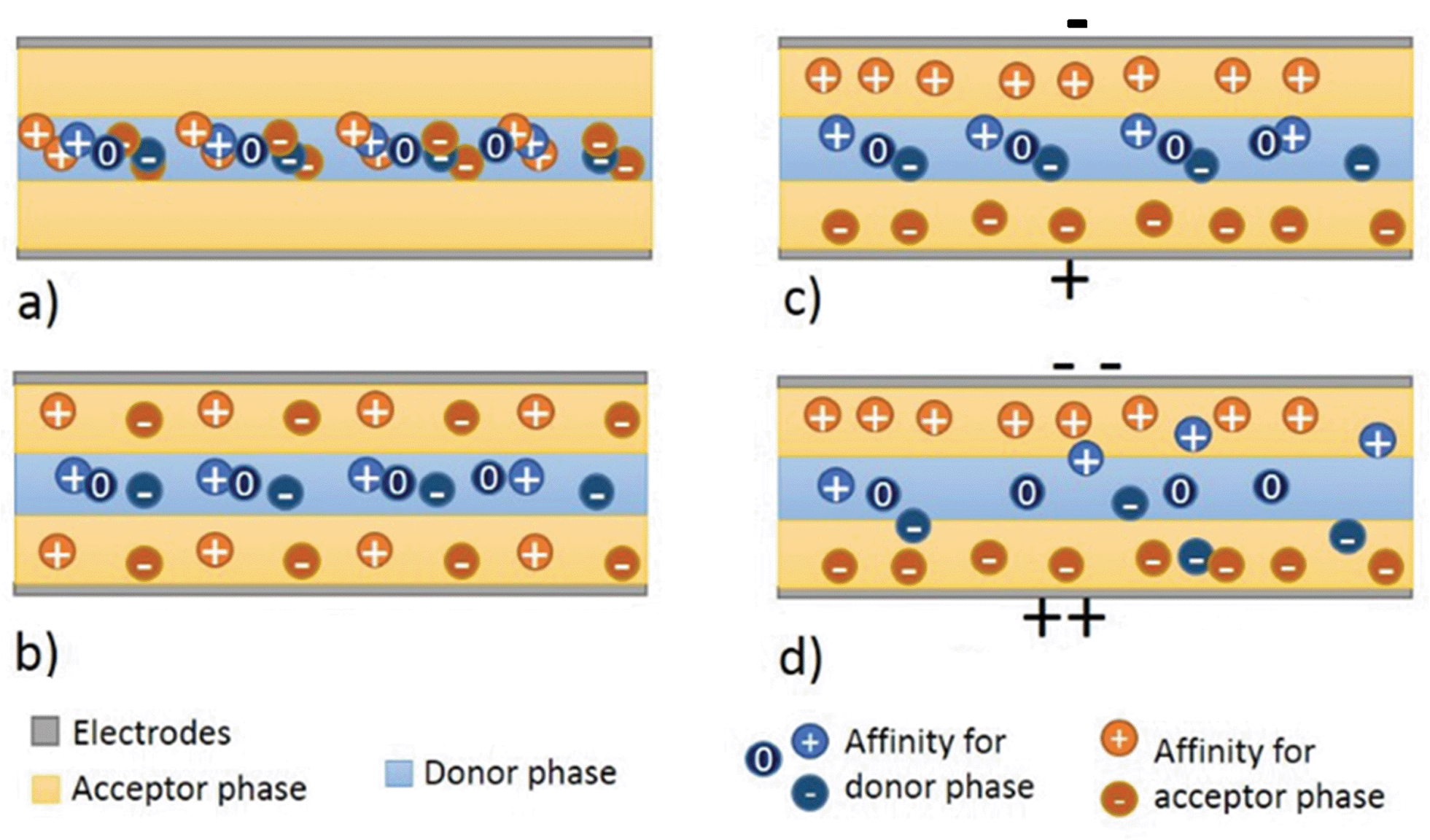 | ||
| Fig. 1 Principle of ATPS electroextraction. (a) Initial conditions, (b) diffusion without electric field, (c) electric field below the threshold and (d) electric fields above the threshold. | ||
The system then performs an electroextraction process26 with the phase interface replacing a physical membrane. The absence of diaphragm simplifies the microfluidic chip fabrication. Additionally, electric field controlled transport also allows one to find the best conditions and for the extraction of target compounds.
As mentioned before, the main difference of the design presented here in comparison to other chips presented in literature is the use of collector channels. This role is performed by the channels 1 and 5 (Fig. 2), placed perpendicularly to the flow. The external electric field is applied across these channels, and the extraction takes place in the region indicated by the dotted square in Fig. 2. The mechanism of the separation is showed in the details as a function of the applied potential in Fig. 3.
 | ||
| Fig. 2 Photograph of the chip used in the extraction with the three streams in different colors. The donor phase is introduced at input 3 and embedded by laminar flow between the acceptor phase from inputs 2 and 4. An additional acceptor phase is introduced by the inputs 1 and 5. These inputs are also used to apply an external electric field and remove the faster molecules from the main flow acting as collector channels. The region indicated by the dotted line is where the extraction takes place. Sample collection was done in the output. | ||
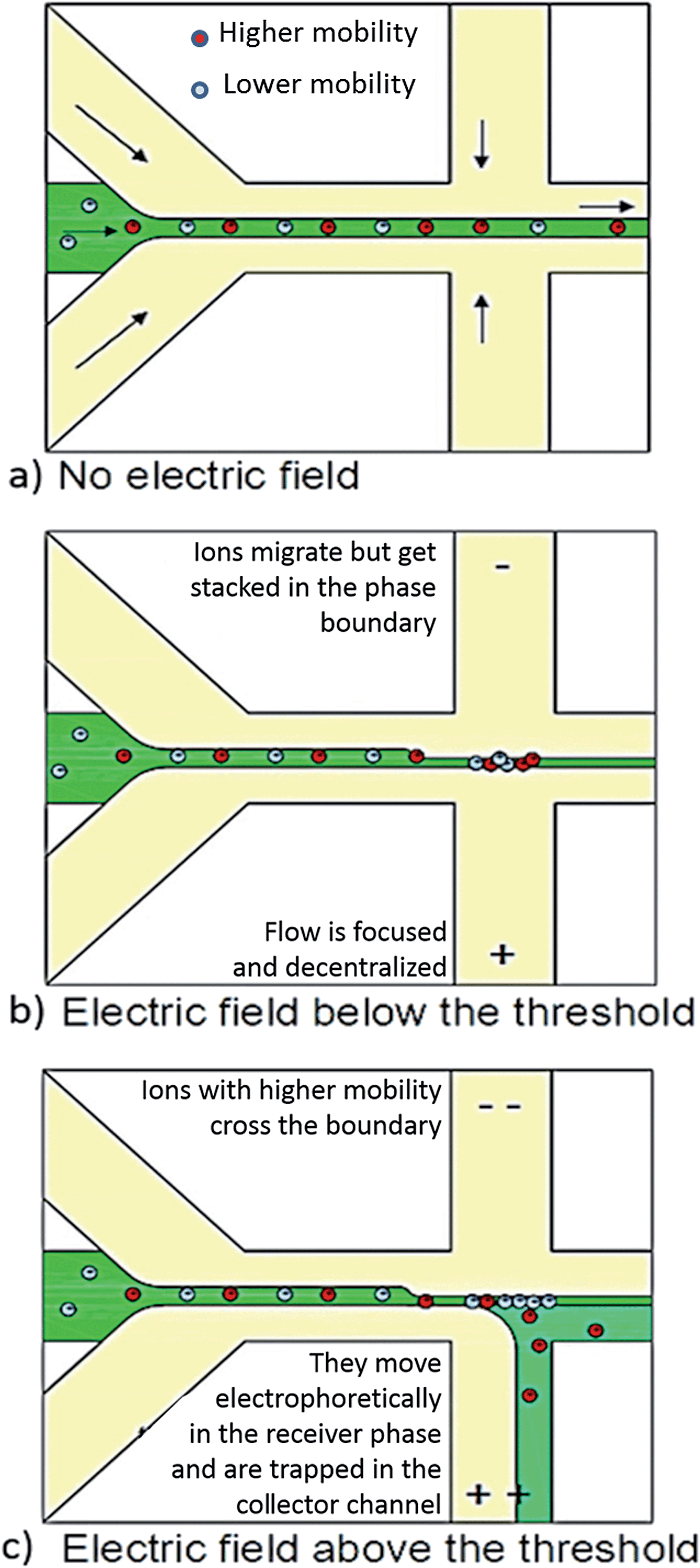 | ||
| Fig. 3 Schematic representation of the effect of the field in the flow when (a) no electric field (b) an electric field below the threshold and (c) an electric field above the threshold is applied. | ||
When no potential is applied, the ions remains in the donor phase, centralized by the parallel laminar flow (Fig. 3a). When electric fields smaller than the threshold are used, the ions migrate but get stuck in the phase boundary. Sample stream is narrow (or focused) and decentralized (Fig. 3b). When the threshold is reached, some ions cross the boundary. The part with higher electrophoretic mobility migrates into the collector channel and is removed from the main flow. This results in a second level of separation (Fig. 3c).
One way of influencing the mobility, and thus the separation efficiency, is the modification of the background electrolyte pH. We have calculated the mobilities as function of pH (Fig. 4) for lysine, tryptophan and glutamic acid. Effective separation can be obtained when the pH range from 4.5 to 11, but pH values lower than 7 are prohibitive due to the gelation of caseinate donor phase.27 If the compounds of interest could not be separated using basic pH, other polymers can be evaluated as acceptor phase. The evaluation of different phases is not the scope of this work.
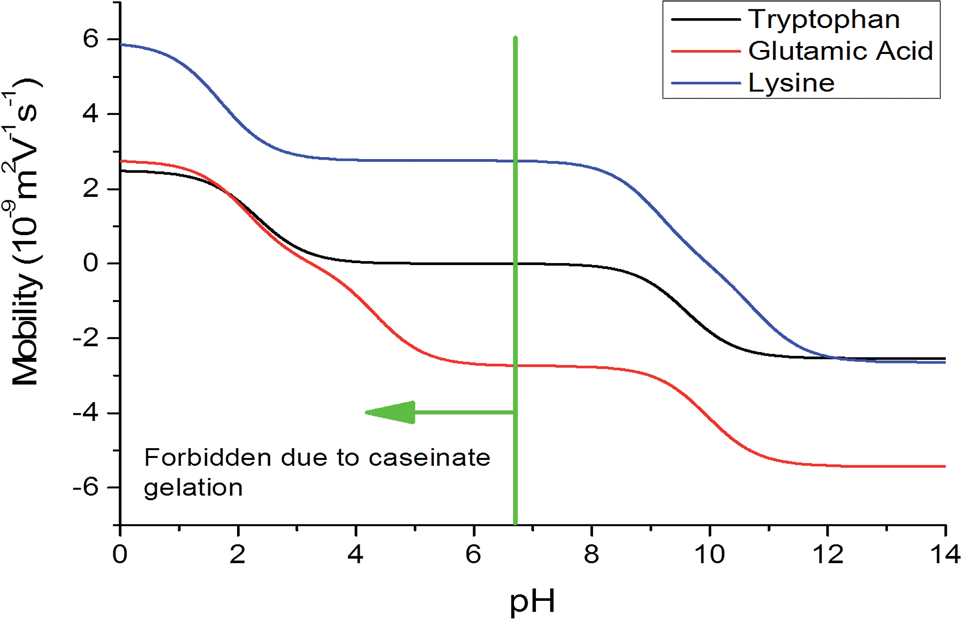 | ||
| Fig. 4 Calculated values of effective mobilities of the amino acids as a function of pH. | ||
Additionally, it is expected that highly conductive electrolytes increase the incidence of air bubbles and flow instabilities in the system. Mobility of the amino acids is supposed to get lower electrolytes with lower conductivity, thus making separation less effective so intermediary values of conductivity should be used.
The other parameter that may affect the results are the flow rates used. The presents an schematic of the theoretical movement of an ion in the extraction space (Fig. 5). The variable df is the displacement caused by fluidic motion, de is the electrophoretic displacement, x is the minimum distance that the ion should be displaced to be trapped by the collector channel and w is the channel width.
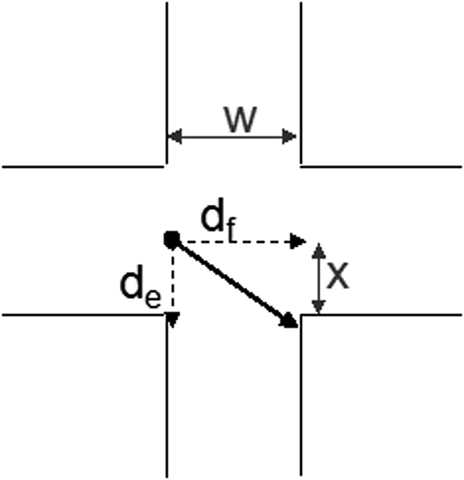 | ||
| Fig. 5 Schematic of the ion movement across the region of the applied electric field. The distances can be used to estimate the acceptor flow rate necessary to trap the target compound. | ||
The minimum value of residence time (tr) to promote the second level of separation can be calculated according to the eqn (1), where vi is the velocity of the ion perpendicular to the flow, μ its mobility and E is the applied electric field.
| vi = μE = x/tr; | (1) |
The residence time can be used in the set of eqn (2) to determinate the flow rates (![[u with combining dot above]](https://www.rsc.org/images/entities/i_char_0075_0307.gif) ), in which vf is the flow linear velocity and Ac is the channel cross-section area.
), in which vf is the flow linear velocity and Ac is the channel cross-section area.
| tr = w/vf; |
|
vf = /Ac
| (2) |
Substituting tr in eqn (2) and rearranging them results in eqn (3). Solving the equation to the chip and field parameters presented in this paper and the mobility of glutamic acid in pH 10, it is possible to conclude that the flow rate should be between 0.2 to 0.3 μL min−1. In this calculation the EOF was not included.
 | (3) |
3. Experimental
3.1. Chemicals
All chemicals are from Sigma Aldrich GmbH (Germany), unless other information is provided. The acceptor phase for the extraction was 10% (m V−1) caseinate solution prepared by dissolving sodium caseinate in 50 mM tetraborate buffer (pH 8–10). The donor phase was 6% (m V−1) poly(ethylene-glycol) (PEG) (MW 6000 Da) also dissolved in the same tetraborate buffer solution. Fluorescein-labelled glutamic acid (AppliChem GmbH, Germany) and lysine were used for some measurements. Food dyes (E133, E110 – Funfood4you GmbH, Germany) were also mixed in the donor phase for visualization purposes.3.2. Experimental set-up
An optical microscope image of the chip used in the experiments is presented in Fig. 2. Polycarbonate microchips were supplied by Mikrofluidic ChipShop GmbH (Germany). The chips were chosen due to their configuration, with 5 inputs and a single output, making the use of the external channels as collectors possible. Each channel had a width and depth of 70 μm each. In our experiments, the external (red) and intermediate flow (white) carried the acceptor phase, both with a flow rates of 0.5 μL min−1. The internal flow (blue) was the donor phase with a flow rate of 0.3 μL min−1. This value is close to the one calculated using eqn (3).The electrodes were positioned in the connections of inputs 1 and 5, with all the other inputs floating. The external electric field was applied by a HVS448 high voltage sequencer (Labsmith Inc., USA).
First of all, an experiment was conducted to demonstrate that the membrane-like behavior of the interface occurs only when two different phases are used. To demonstrate this, a test was conducted using PEG as donor and acceptor phase.
Following this, we tried to demonstrate the possibility of using collector channels to improve the separation. The experiment setup could be modified to collect separately the donor and acceptor phases. The concentration of each amino acid present in the output flow was measured using HPLC (Agilent GmbH, Germany). The values are expressed as fractions of the value obtained without an external field for illustration purposes.
Finally, we present a possibility of improving separation by the labeling of the amino acids. FITC reaction was used to modify the final charge and mass of the amino acids, inducing some changes in its electrophoretic behavior.
4. Results and discussion
4.1. Influence of the background electrolyte properties
As expected, the best results were obtained between pH 9.0 and 10.0, so the highest pH was chosen to the tests. Also the pH change as well as the buffer composition may result in different electroosmotic flow values. It could favor or be an obstacle to trapping the molecules in the collector channels.4.2. The role of phase differences
As mentioned in the Experimental set-up description, the first experiment was conducted using PEG as donor and acceptor phase. In such conditions, the two different phases formed due to the laminar flow are identical.The recoveries observed in the output can be seen in Fig. 6. The recovery observed with the applied field of 5.9 kV m−1 is lower than 40%. It indicates that the extraction also occurs also at low electric fields. The electrophoretic migration of the ions across the phase boundary and through the collector channel is not avoided by the phase boundary and thus the recovery is very low.
 | ||
| Fig. 6 Recovery of glutamic acid and lysine in the output stream, after extraction, for different electric fields using PEG as donor and acceptor phase. | ||
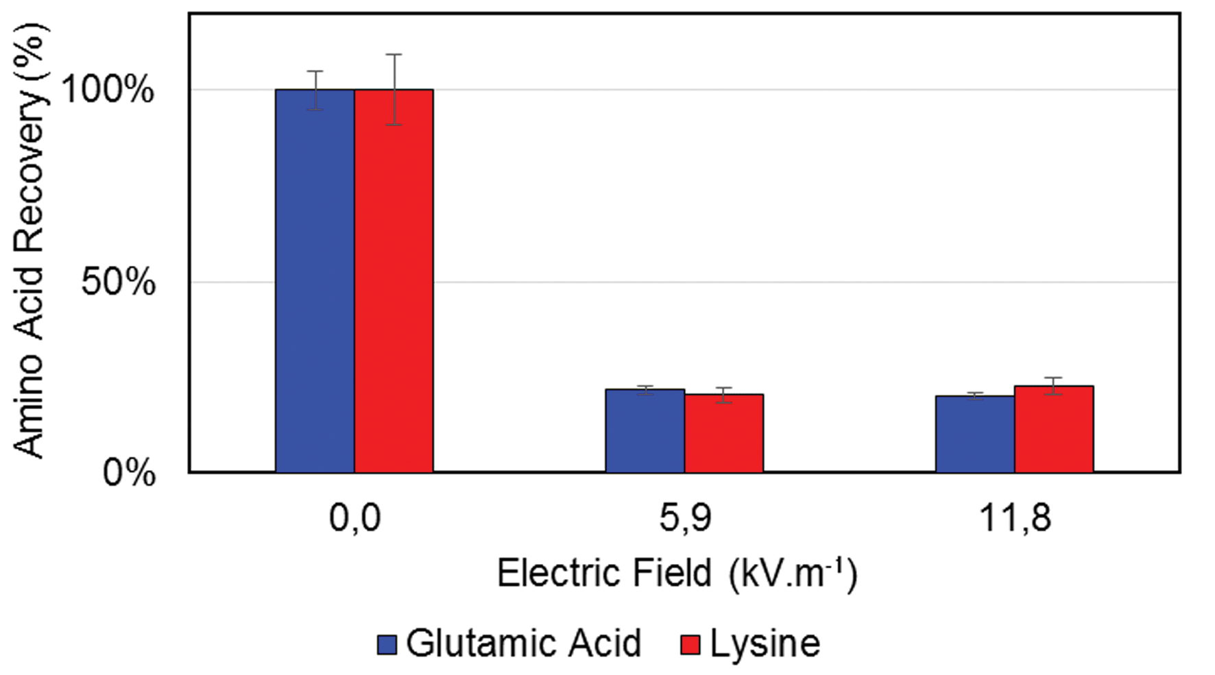
With the replacement of the PEG-acceptor phase by caseinate solution, an ATPS was formed, and a different behavior was observed. The recoveries obtained in this second experiment are presented in Fig. 7.
 | ||
| Fig. 7 Recovery of glutamic acid and lysine in the output stream, after extraction, for different electric fields. PEG–caseinate two phase system. | ||
In this circumstance, the phase boundary acted as a virtual membrane, promoting the selective diffusion of molecules according to the electric field strength. Practically no diffusion was observed across the phase boundary without an external electric field (as described in Fig. 3a). The application of electric potential in inputs 1 and 5, resulted in an external electric field with a strength of 7.4 kV m−1 and caused the movement of amino acids inside the donor phase, based on their mobility. Nevertheless, the field strength has not caused the amino acid migration across the phase boundary (similarly to what is described in Fig. 3b) and the recoveries were close to those observed with no electric field. Finally, with an applied electric field strength of 14.7 kV m−1 or higher, the molecules with a higher mobility were able to cross the phase boundary. Once they reached the acceptor phase they migrated according to the applied potential (Fig. 3c). Because the phase boundary behaves as a selective membrane and the ability to cross the barrier is related to the physicochemical properties of the molecule, the amount of amino acids present in the output flow is inversely proportional to their mobility. The recovery of glutamic acid and tryptophan was 70 ± 4.1% while the lysine value was slightly lower (47 ± 4.2%).
This leads to the conclusion that the use of two different phases as donors and acceptors results in membrane-like behavior of the phase boundary, and that there is a threshold in the electric field for the migration of molecules across it. Once the threshold is achieved, the amount of molecules that migrate seems to be proportional to the applied potential.
These results indicate that the use of a two-level separation process represents an option for parallel selection of multiple target compounds. However, changes in the extraction media properties such as pH, conductivity etc. can increase the differences in mobilities between some of the compounds in the sample. The technique can also be used for sample clean-up by removing undesirable components from the complex matrix.
4.3. Improvement of selectivity by amino acid functionalization
Fluorescein isothiocyanate (FITC) labelling was used to increase the difference in mobilities. The lysine functionalized with two molecules of FITC was expected to present a much higher mobility compared to glutamic acid, according to the charge vs. pH curve we obtained by theoretical analysis (Fig. 8). The charge is one of the main influences in the mobility, so the charge vs., pH curve is a good indicative of the differences in mobility resulting from the functionalization. | ||
| Fig. 8 Charge vs. pH estimatives for labelled lysine and glutamic acid. | ||
It was confirmed by the low values of recoveries (Fig. 9). The recoveries of both amino acids were similar either without an external electric field or with a field with the strength of 7.4 kV m−1. The ratio between glutamic acid and lysine after extraction at 14 7 kV m−1 was 87% higher than when no field is used. With a field strength of 22.1 kV m−1 almost complete purification was achieved. However, with these conditions half of the glutamic acid was lost, because part of the glutamic acid molecules are also able to migrate through the border under high electric fields, and due to this is trapped in the collector channel. The system also exhibited several instabilities, such as bubble formation and excessive Joule heating resulting from the high magnitude of the electric current. These represent obstacles for hours-long application.
 | ||
| Fig. 9 Recovery of the FITC labelled amino acids in the output stream as a function of the electric field strength. | ||
5. Conclusion
In this paper we demonstrated the possibility of using ATPS for electroextraction of amino acids in a two-level process. We verified that the mobility has a strong influence on the migration behavior as well as the selectivity. These promising results open the way toward selective extraction and separation by controlling the external electric field as well as the mobility of the amino acids.Acknowledgements
Authors are acknowledging M. Altmeyer, from KIST-Europe, M. Fritz and E. Heinzle, Chemistry institute of Saarland University for the HPLC analysis and S. J. Lee for the help with Experimental set up. C. Campos is grateful to São Paulo Research Foundation (FAPESP) for financial support, grant numbers 2011/02477-3 and 2013/06625-2.Notes and references
- P. L. Kole, G. Venkatesh, J. Kotecha and R. Sheshala, Biomed. Chromatogr., 2011, 25, 199–217 CrossRef CAS PubMed.
- L. Ramos, J. Chromatogr. A, 2012, 1221, 84–98 CrossRef CAS PubMed.
- G. M. Whitesides, Nature, 2006, 442, 368–373 CrossRef CAS PubMed.
- A. Escarpa, Lab Chip, 2014, 14, 3213–3224 RSC.
- S. Koning, H.-G. Janssen and U. A. T. Brinkman, Chromatographia, 2009, 69, 33–78 Search PubMed.
- V. García-Cañas, C. Simó, M. Herrero, E. Ibáñez and A. Cifuentes, Anal. Chem., 2012, 84, 10150–10159 CrossRef PubMed.
- B. J. A. Berendsen, L. A. A. M. Stolker and M. W. F. Nielen, TrAC, Trends Anal. Chem., 2013, 43, 229–239 CrossRef CAS PubMed.
- K. Kalachova, T. Cajka, C. Sandy, J. Hajslova and J. Pulkrabova, Talanta, 2013, 105, 109–116 CrossRef CAS PubMed.
- Á. Ríos and M. Zougagh, TrAC, Trends Anal. Chem., 2013, 43, 174–188 CrossRef PubMed.
- M. G. Freire, C. M. S. S. Neves, I. M. Marrucho, J. N. Canongia Lopes, L. P. N. Rebelo and J. a. P. Coutinho, Green Chem., 2010, 12, 1715–1718 RSC.
- P. A. J. Rosa, I. F. Ferreira, A. M. Azevedo and M. R. Aires-Barros, J. Chromatogr. A, 2010, 1217, 2296–2305 CrossRef CAS PubMed.
- H. D. Willauer, J. G. Huddleston and R. D. Rogers, Ind. Eng. Chem. Res., 2002, 41, 1892–1904 CrossRef CAS.
- X. Xie, Y. Wang, J. Han and Y. Yan, Anal. Chim. Acta, 2011, 687, 61–66 CrossRef CAS PubMed.
- M. Simeone, A. Alfani and S. Guido, Food Hydrocolloids, 2004, 18, 463–470 CrossRef CAS PubMed.
- L. Ferreira, P. P. Madeira, L. Mikheeva, V. N. Uversky and B. Zaslavsky, Biochim. Biophys. Acta, 2013, 1834, 2859–2866 CrossRef CAS PubMed.
- B. R. Babu, N. K. Rastogi and K. S. M. S. Raghavarao, Chemical Engineering and Processing: process intensification, 2008, 47, 83–89 CrossRef CAS PubMed.
- F. Tjerneld, S. Berner, A. Cajarville and G. Johansson, Enzyme Microb. Technol., 1986, 8, 417–423 CrossRef CAS.
- J. A. Asenjo and B. A. Andrews, J. Chromatogr. A, 2011, 1218, 8826–8835 CrossRef CAS PubMed.
- T. Z. Jia, C. Hentrich and J. W. Szostak, Origins Life Evol. Biospheres, 2014, 44, 1–12 CrossRef CAS PubMed.
- A. Salic, A. Tusek, D. Fabek, I. Rukavina and B. Zelic, Food Technol. Biotechnol., 2011, 49, 495–501 CAS.
- G. Münchow, F. Schönfeld, S. Hardt and K. Graf, Langmuir, 2008, 24, 8547–8553 CrossRef PubMed.
- Y. S. Song, Y. H. Choi and D. H. Kim, J. Chromatogr. A, 2007, 1162, 180–186 CrossRef CAS PubMed.
- G. Münchow, S. Hardt, J. P. Kutter and K. S. Drese, JALA, 2006, 11, 368–373 Search PubMed.
- G. Münchow, S. Hardt, J. P. Kutter and K. S. Drese, Lab Chip, 2007, 7, 98–102 RSC.
- T. Hahn and S. Hardt, Anal. Chem., 2011, 83, 5476–5479 CrossRef CAS PubMed.
- Y. Kim, M. Cha, Y. Choi, H. Joo and J. Lee, Chem. Phys. Lett., 2013, 561–562, 63–67 CrossRef CAS PubMed.
- H. G. M. Ruis, P. Venema and E. van der Linden, Food Hydrocolloids, 2007, 21, 545–554 CrossRef CAS PubMed.
| This journal is © The Royal Society of Chemistry 2014 |