
Simple approach for the immobilization of horseradish peroxidase on poly-L-histidine modified reduced graphene oxide for amperometric determination of dopamine and H2O2†
A. T. Ezhil Vilian and
Shen-Ming Chen*
Department of Chemical Engineering and Biotechnology, National Taipei University of Technology, No.1, Section 3, Chung-Hsiao East Road, Taipei 106, Taiwan (R.O.C). E-mail: smchen78@ms15.hinet.net; Fax: +886 2270 25238; Tel: +886 2270 17147
First published on 7th October 2014
Abstract
In this work, immobilization of horseradish peroxidase (HRP) on poly-L-histidine (P-L-His) modified reduced graphene oxide (RGO) was demonstrated. The HRP/P-L-His-RGO bio-nanocomposite film was prepared through layer-by-layer (LBL) assembly. Scanning electron microscopy, Fourier transform infrared spectroscopy, electrochemical impedance spectroscopy, and UV-Vis spectroscopy were adopted to monitor the uniformity of the LBL assembly of the HRP/P-L-His-RGO bio-nanocomposite film. The immobilized HRP exhibited excellent electrocatalytic activity towards the reduction of hydrogen peroxide (H2O2). The catalysis currents showed a linear relationship with H2O2 concentration, ranging from 0.2 to 5000 μM. The detection limit (S/N = 3) of H2O2 was 0.05 μM. The apparent Michaelis–Menten constant (Km) was calculated to be 1.2 mM. Moreover, the modified electrode displayed a rapid response (5 s) to H2O2 with good stability and reproducibility. Based on the HRP/P-L-His-RGO bio-nanocomposite film, a third-generation reagentless biosensor was constructed for the determination of H2O2.
1. Introduction
The study of the electrochemical behaviour of dopamine (DA) has received considerable attention from researchers and has been extensively studied since the 1950s.1 DA is a crucial catecholamine neurotransmitter existing in the brain and the peripheral nervous system of mammals.2,3 It has been found that a loss of DA-containing neurons may occur in some serious diseases such as Parkinson's, schizophrenia, epilepsy, and HIV infection to name a few.4,5 However, DA has a close oxidation potential with some interference, which can cause poor selectivity and sensitivity in the electrochemical determination of DA in brain fluids if it coexists with many interfering compounds.6 It is necessary to develop a simple and rapid analytical method for the determination of DA that will overcome these problems.7 Over the past few years, several methods have been applied for the analytical determination of DA in pharmaceutical and clinical preparations, including, spectrophotometry,8 chemiluminescence,9 high performance liquid chromatography,10 and electrochemical methods. However, most of the abovementioned methods have some disadvantages, such as time consuming, high costs, low sensitivity and complicated pretreatments.11 On the other hand, electrochemical methods have been actively developed owing to their high sensitivity, rapid response time, low cost and simplicity of use.12 Recently, considerable attention has been focused on the development of biosensors due to their advantages of easy preparation, fast detection, rapidity and high sensitivity.13Hydrogen peroxide (H2O2) is a well-known oxidizing agent, which plays an important role in the production of textiles, cleaning products, organic compounds, and food industry.14 Owing to the increased usage of H2O2, it has been released into the environment in large amounts. Thus, developing a simple, rapid, reliable and highly sensitive method for the determination of trace amounts of H2O2 at physiological pH has become a necessity.15 Furthermore, H2O2 is also a vital intermediate that is formed in oxidase enzymes and its accurate and rapid determination is a key factor for the development of efficient biosensors.16 In recent years, there have been numerous attempts to develop enzyme-based electrochemical biosensors for the detection of H2O2. However, efforts have been limited by the problems of poor stability, high cost of enzymes, complicated immobilization procedures and critical operational conditions due to sensitivity of enzymes to pH, temperature, humidity, ionic detergents and toxic chemicals. It has become necessary to develop a simple enzyme immobilization strategy to achieve a device capable of sensing H2O2 with high sensitivity.17 Many techniques, such as chemiluminescence,18 spectrophotometry,19 titrimetry,20 and electroanalytical methods,21,22 have been employed for the detection and determination of H2O2. Among these methods, enzyme-based electroanalytical methods are more attractive because of their low cost, operational simplicity, high sensitivity and real-time detection.23 Based on the efficient catalyzing ability of horseradish peroxidase (HRP) to decompose H2O2, various types of biosensors have been developed.24
HRP is a common enzyme widely used in H2O2 biosensors due to its easy availability, and low cost.25 HRP contains a heme prosthetic group, which catalyzes the oxidation of different substrates as a consequence of the protein active site with the resting state of the heme-iron Fe(II).26 However, some of the methods for enzyme immobilization are prone to problems such as low reproducibility, poor enzymatic activity, and poor spatial control during the deposition process. The immobilization of HRP on the electrode surface is difficult.27 In recent years, immobilization of HRP through several methods, including absorption,28 cross linking,29 layer by layer assembly,30 sol–gel entrapment,31 and electropolymerization, have been proposed. Among these methods, the physical entrapment of enzymes is needed for the production of a more stable sensor with a reduced loss of enzyme during measurement as well as a simpler and less-time consuming fabrication process, while still ensuring high stability and sensitivity, and biocompatibility, which can affect the activity of the enzyme.32
Specifically, graphene is a two-dimensional nanomaterial that has received intense attention due to its unique physical and chemical properties, such as low resistivity, outstanding mechanical properties and large specific surface area.33,34 With the advantages of graphene substrate and active metal nanoparticle components, a new class of hybrid materials, such as graphene supported metal nanocomposites, have been developed.35 They have shown great potential for extensive applications in many advanced fields such as memory electronics, optoelectronic transistors,36 catalysis,37 energy storage,38 and electrochemical sensors and biosensors.39,40
To the best of our knowledge, there has been no report on the fabrication of HRP/P-L-His-RGO nanocomposites on a glassy carbon electrode (GCE) surface for the determination of DA and H2O2. In this work, a novel amperometric biosensor based on the immobilization of HRP on the electrochemically polymerized L-His modified RGO has been proposed. The amine groups in P-L-His provide positive surface charges on the P-L-His-RGO, enabling a favourable microenvironment for the immobilization of HRP. This simple immobilization strategy demonstrates the great potential for P-L-His-RGO composite films to be used as a biomatrix for proteins in new generation biosensors. The proposed HRP/P-L-His-RGO biosensor has excellent sensitivity, wide linearity, favourable stability, good reproducibility, low detection limit and a low Michaelis–Menten constant. In addition, the HRP/P-L-His-RGO composite film was applied for the determination of H2O2 and DA in real samples.
2. Experimental procedure
2.1 Reagents
The graphite powder (<20 μm) used in the experiments was purchased from Sigma-Aldrich. L-Histidine, H2O2 (30%), dopamine hydrochloride, NaH2PO4 and Na2HPO4 were supplied by Sigma-Aldrich. Horseradish peroxidase (E.C. 1.11.1.7 type-VI-A-S/5 mg, Armoracia rusticana source, 1840 U mg−1) was provided by Sigma. Phosphate buffer solution (PBS) was prepared by mixing standard stock solutions of Na2HPO4 and NaH2PO4. The supporting electrolyte was a 0.05 M phosphate buffer solution (PBS). All experiments were performed using PBS at room temperature (approximately 25 °C). All other chemicals were of analytical grade and were used as received. The water used throughout the experiments was purified by a Milli-Q water system (resistivity 18.25 MU cm, Millipore).2.2 Apparatus
All electrochemical experiments were performed on a CHI 405A electrochemical work station with a conventional three-electrode system comprised of a platinum wire as the auxiliary electrode, an Ag/AgCl electrode as the reference electrode, and a modified glassy carbon electrode (GCE) as the working electrode. Rotating disc electrode (RDE) and amperometric measurements were performed using a CHI 405A electrochemical workstation with an analytical rotator AFMSRX (PINE Instruments, USA, Japan). Scanning electron microscopy (SEM) was performed using a Hitachi S-3000 H instrument (Hitachi, Japan). Energy dispersive X-ray analysis (EDX) was recorded using a HORIBA EMAX X-ACT (Model 51-ADD0009) instrument. UV absorption spectra were collected using a Model UV-3300 spectrophotometer (Hitachi, Japan). Fourier transform infrared (FT-IR) measurements were carried out using a Perkin Elmer spectrophotometer RXI. X-Ray photoelectron spectroscopy (XPS) was performed using a PHI 5000 Versa Probe equipped with an Al Kα X-ray source (1486.6 eV). Electrochemical impedance spectroscopy (EIS) measurements were carried out in the frequency range from 0.1 Hz to 1 MHz (IM6ex ZAHNER Kroanch, Germany).2.3 Synthesis of GO
The graphene oxide (GO) used in this work was prepared using the modified Hummers method.41 Specifically, graphite powder (5.0 g) and 25 g of KMnO4 were sequentially added to concentrated H2SO4 (150 mL) with constant stirring under ice-cold conditions. The resulting mixture was then continuously stirred at 35 °C for 5 h. Then, it was diluted with 600 mL of deionized water and the temperature was kept under 50 °C. Subsequently, 30 mL of 30% H2O2 was added drop wise into this mixture. The obtained solid product was repeatedly filtered and washed with a 1![[thin space (1/6-em)]](https://www.rsc.org/images/entities/char_2009.gif) :10 HCl aqueous solution (1000 mL) to remove the metal ions, and then further washed with 1000 mL of deionized water until the solution pH became neutral (pH 6.5). Finally, the obtained dark-yellow solid was dried in a vacuum oven at 40 °C for 48 h and then ground to fine powder. The as-obtained powder was dispersed in water and sonicated for 1 hour to obtain well-exfoliated GO.
:10 HCl aqueous solution (1000 mL) to remove the metal ions, and then further washed with 1000 mL of deionized water until the solution pH became neutral (pH 6.5). Finally, the obtained dark-yellow solid was dried in a vacuum oven at 40 °C for 48 h and then ground to fine powder. The as-obtained powder was dispersed in water and sonicated for 1 hour to obtain well-exfoliated GO.
2.4 Fabrication of HRP/P-L-His-RGO/GCE
Before modification, the GCE electrode (3 mm) was first polished carefully with 0.05 μm of alumina slurry, and washed ultrasonically in water. Then, it was electrochemically cleaned in 0.1 M H2SO4 by cyclic potential scanning between −0.2 and 1.2 V until a standard cyclic voltammogram was obtained. Finally, the GCE electrode was sonicated in water and absolute ethanol before being dried in a nitrogen stream before use. Schematic illustration shown in Scheme 1 provides an overview of the fabrication process to prepare the HRP biosensor. Prior to use, the as-synthesized GO (1 mg) was dissolved by sonication in 1 mL of water for 1 h. Then, 5 μL of the GO suspension was dropped onto the GCE surface, followed by evaporation of the solvent under an infrared lamp. The GO modified GCE was transferred to an electrochemical cell containing the 0.05 M PBS electrolyte at pH 5 and 5 mM of l-His. 30 cycles were recorded over a potential range of 0.0 to −1.5 V vs. Ag/AgCl as displayed in Fig. S1.† During the first cathodic potential scan, a large cathodic peak appears at −1.0 V with an onset potential of −0.75 V, which is attributed to the reduction of the oxygen containing functional groups in GO. The cathodic current decreased continuously for each cycle, suggesting the effective reduction of the functional groups in GO, the deposition of highly conducting material onto the GCE electrode and the electrochemical generation of the RGO + P-L-His film on the GCE. Then, a fresh HRP solution was prepared by dissolving 10 mg of HRP in 1 mL of 0.05 M PBS at pH 7.5 μL of HRP solution was drop casted onto the surface of the RGO + P-L-His modified GCE electrode using a microsyringe and allowed to dry at 4 °C for 24 h. HRP was immobilized onto the RGO + P-L-His modified GCE through the electrostatic interactions between the positively charged P-L-His and negatively charged HRP molecules. After each modification step the electrode surface was rinsed with PBS. Finally, 5 μL of 0.1% Nafion was coated on the modified electrode surface to form a protective film. The as-prepared enzyme modified electrode was dried at 4 °C until used further.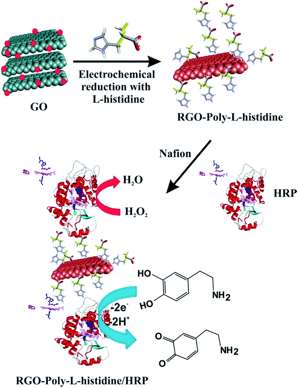 | ||
| Scheme 1 Schematic illustration of the procedure used for the preparation of HRP/P-L-His-RGO film modified glassy carbon electrode. | ||
3. Results and discussion
3.1 Surface studies and elemental analysis
Fig. 1 illustrates the SEM images of the as-prepared (A) P-L-His-RGO and (C) HRP/P-L-His-RGO bio-nanocomposites. The P-L-His-RGO contains flat, wrinkled sheets that are stacked with each other. Small plate and rod-like P-L-histidine molecules are also formed on the RGO sheets. Upon modification with HRP, several bead-like, globular structures are formed on the P-L-His coated RGO sheets, which can be attributed to the electrostatic interactions between the negatively charged HRP and the positively charged P-L-His coated RGO. The EDX spectrum of the P-L-His-RGO sheets (c) reveals the presence of C (50%), O (40%) and N (10%) related to the amino groups of histidine (see Fig. 1B). SEM results confirm the formation of HRP/P-L-His-RGO on the ITO surface, suggesting that the interaction between RGO/P-L-His and HRP indeed occurs, and may even influence the morphology of the dry films. Furthermore, the terminal functional groups of the positively charged P-L-His-RGO provide more active sites for the immobilization of the HRP biocomposite, leading to facile and efficient electron transfer.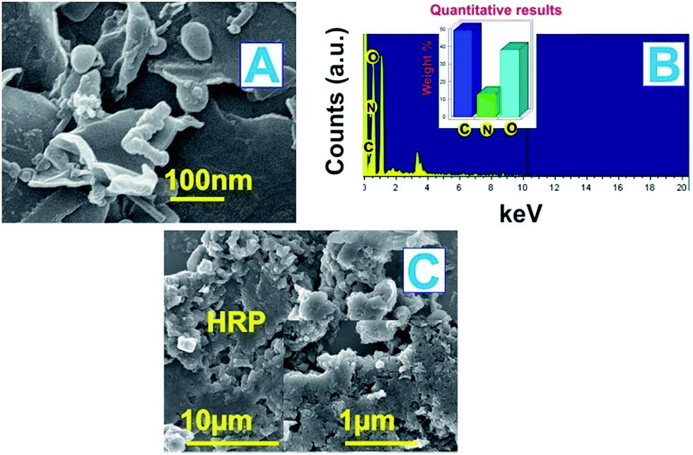 | ||
| Fig. 1 (A) SEM image of P-L-His-RGO, (B) EDX spectra of the P-L-His-RGO nanocomposite, and (C) SEM image of the HRP/P-L-His-RGO bio-nanocomposite films. | ||
Fig. 2(A&B) shows TEM images of the as-prepared (A) RGO and (B) P-L-His-RGO nanocomposite films. Fig. 2A shows the as-prepared reduced graphene was thin and transparent, which consist of a few layers of sheet-like structures and (B) shows the P-L-His particles have been deposited as a distorted shaped thin sheet-like structure, which were uniformly dispersed in the RGO sheets. The presence of poly-L-His is clearly evident in the EDX analysis shown in Fig. 1B.
 | ||
| Fig. 2 TEM images of the (A) RGO and (B) P-L-His-RGO nanocomposite films. (C) XPS survey of P-L-His-RGO. (D) C1s XPS spectra of the P-L-His-RGO nanocomposite film. (E) N1s XPS spectra of the P-L-His-RGO nanocomposite film. | ||
The elemental composition of the P-L-His-RGO film after various stages of surface modification was ascertained by XPS (Fig. 2C). It is well known that the bands centered at 284.8 and 531.0 eV are associated with C1s and O1s, respectively. It can be clearly seen that there is a significant decrease in the intensity of the O1s peaks of RGO compared with that of the P-L-His/RGO, which can be attributed to the loss of oxygen in GO as a result of electrochemical reduction (Fig. 2D). A new peak observed at 404.2 eV corresponds to N1s, which can be assigned to the nitrogen atoms in the amino groups of P-L-His (Fig. 2E). In addition, the new peak observed at 286 eV can be attributed to the C–N of P-L-His.42 The XPS results therefore validate the electrodeposition of the nitrogen containing P-L-His on RGO.
3.2 Characterization of the HRP/P-L-His-RGO modified film
Fig. S2(a)† shows the FT-IR spectra of (a) GO, and (b) P-L-His-RGO. FT-IR spectrum of GO shows the characteristic peaks of –OH (ν = 3440 cm−1 and 1398 cm−1), aromatic –C![[double bond, length as m-dash]](https://www.rsc.org/images/entities/char_e001.gif) C (ν = 1623 cm−1), epoxy –C–O (ν = 1288 cm−1), carboxyl –CO and –C–O (ν = 1741 cm−1) and alkoxy –C–O (ν = 1076 cm−1) groups, revealing the existence of oxygen-containing functional groups on the GO nanosheets.43 For P-L-His-RGO (Fig. S2(b)†), a new band appears at 1656 cm−1, which corresponds to amide I (the –C= O stretch of P-L-His). The band at 1536 cm−1 is assigned to amide II (the –C–N stretch and –C–N–H deformation). Compared with RGO, the CO stretch at 1623 cm−1 for the carboxyl group disappeared, indicating the binding of P-L-His with the RGO surface.
C (ν = 1623 cm−1), epoxy –C–O (ν = 1288 cm−1), carboxyl –CO and –C–O (ν = 1741 cm−1) and alkoxy –C–O (ν = 1076 cm−1) groups, revealing the existence of oxygen-containing functional groups on the GO nanosheets.43 For P-L-His-RGO (Fig. S2(b)†), a new band appears at 1656 cm−1, which corresponds to amide I (the –C= O stretch of P-L-His). The band at 1536 cm−1 is assigned to amide II (the –C–N stretch and –C–N–H deformation). Compared with RGO, the CO stretch at 1623 cm−1 for the carboxyl group disappeared, indicating the binding of P-L-His with the RGO surface.
To examine the nature of the interactions between the HRP and P-L-His-RGO, we recorded the FT-IR spectra (Fig. 3A(a)). The two characteristic peaks centered at 1630 and 1567 cm−1 are assigned to the typical amide I and II absorption bands of HRP. The peak around 1082 cm−1 corresponds to the stretching vibration of C–O in HRP.44 The biocompatibility of the P-L-His-RGO film gives it great potential to be used as a matrix for the immobilization of the HRP enzyme for biosensor fabrication. In addition, as can be seen from Fig. 3A(b), the position of the amide I and II bands of HRP and that of the P-L-His-RGO film appear at the same position, suggesting that the HRP retains its native structure in the HRP/P-L-His-RGO film. In short there has been no denaturation of HRP because it was stabilized through the electrostatic interactions.
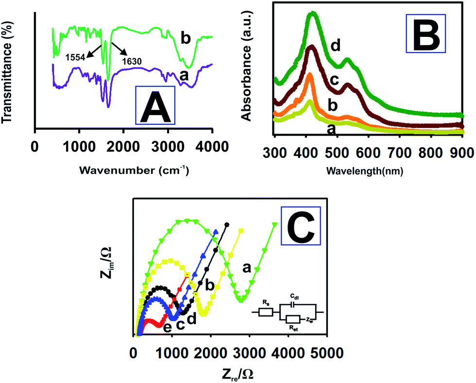 | ||
| Fig. 3 (A) FT-IR spectra of (a) HRP and (b) HRP-P-L-His-RGO film. (B) UV-Vis spectra of (a) HRP and (b) HRP immobilized onto different bilayers (n = b − d) of the P-L-His-RGO films. (C) Nyquist plots for (a) HRP, (b) HRP/P-L-His, (c) RGO/GCE, (d) bare GCE, and (e) P-L-His-RGO/GCE electrodes for 5 mM [Fe(CN)6]3−/4− in a 0.05 M PBS (pH 7.0) solution containing 0.05 M KCl. Amplitude: 5 mV, frequency: 0.1 Hz to 1 MHz. The bottom right inset shows Randles equivalence circuit for the abovementioned electrodes. | ||
The Soret absorption bands associated with the heme groups may provide information about the conformational integrity of the heme proteins and the possible denaturation of conformational change in the heme group region.45,46 As can be seen in Fig. 3B, the Soret band of the HRP molecules appears at 408.8 nm (curve a). HRP immobilized onto different bilayers (n = b − d) of the P-L-His-RGO films exhibits the Soret band at 408.8 nm without any shifts, indicating that no significant denaturation of the protein occurred even after being immobilized onto the P-L-His-RGO composite with increased film thickness. Thus, HRP retained its native structure in the P-L-His-RGO film due to its good film-forming ability and excellent biocompatibility.
3.3 Electrochemical characteristics and direct electrochemistry of HRP on the P-L-His-RGO modified film electrode
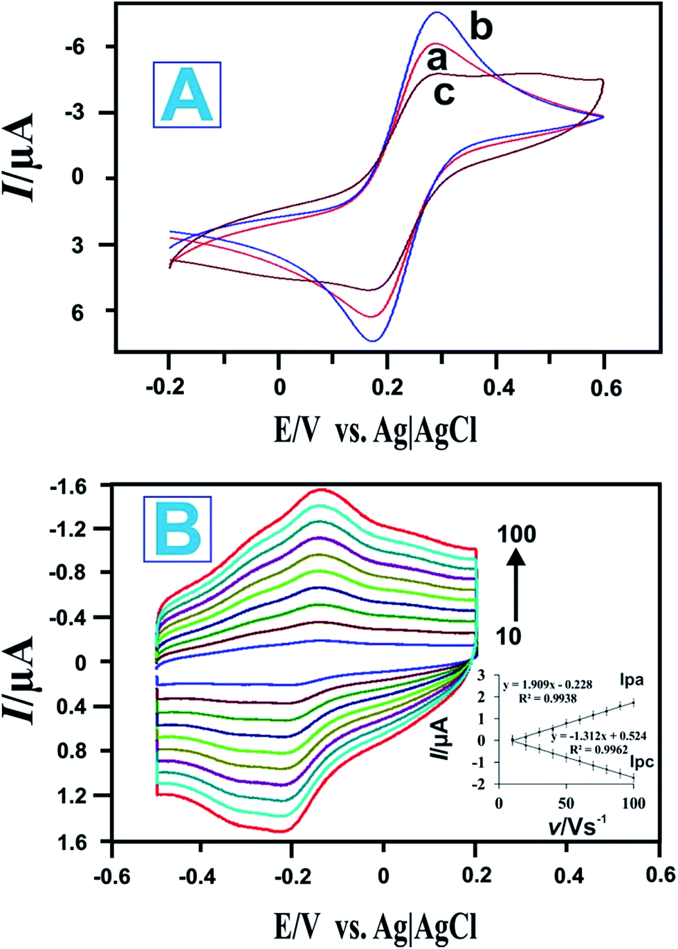
EIS is a sensitive tool for studying the interface properties of surfaces after different steps of modification. The Nyquist plot of the EIS has a semi-circular portion at higher frequencies corresponding to a limited electron transfer process and a linear part at lower frequency ranges representing a diffusion limited process. Typical Nyquist plots of (a) HRP, (b) HRP/P-L-His, (c) RGO/GCE, (d) bare GCE, and (e) P-L-His-RGO/GCE electrodes recorded in [Fe(CN)6]3−/4− solution over a frequency range of 0.1 Hz to 1 MHz are shown in Fig. 3C. The inset to Fig. 3C shows the equivalent circuit comprised of the ohmic resistance of an electrolyte solution (Rs), Warburg impedance (Zw), capacitance (C), and apparent charge transfer resistance (Ret). As depicted in Fig. 3C(d), the bare GCE electrode exhibits a Ret value of 1200 Ω. After being modified with RGO, the Ret value of the RGO/GCE electrode decreased to 1120 Ω (see Fig. 3C(c)). Further modification of RGO/GCE with P-L-His decreased the Ret value to 730 Ω, possibly due to the improved electron transport at the electrode interphase as a result of the electrostatic attraction between the positive charges in the amino groups of the L-His-RGO modified GCE electrode and the negatively charged [Fe(CN)6]3−/4− redox probe (see Fig. 3C(e)). When the HRP enzyme was immobilized on the L-His-RGO modified GCE electrode, the Ret value increased to 1900 Ω (see Fig. 3C(b)), owing to the electrostatic repulsions between the negatively charged HRP and the negatively charged Fe(CN)6]3−/4− redox electrochemical probe. The EIS data indicates that HRP was successfully assembled on the P-L-His-RGO surface.Fig. 4A shows the cyclic voltammetric responses of the (a) bare GCE, (b) P-L-His-RGO and (c) HRP-L-His-RGO modified GCE electrodes in 5 mM K3[Fe(CN)6] solution containing 0.1 M KCl. Fig. 4A shows the cyclic voltammetry (CV) curve of the (a) bare GCE witnessed a pair of well-defined redox peaks with anodic (Epa) and cathodic (Epc) peak potentials of 0.201 and 0.110 V, respectively, and redox peaks with a potential difference of 91 mV, which are attributed to the redox behavior of [Fe(CN)6]3−/4−. Fig. 4A(b) shows an obvious increase in the redox peak current after the deposition of P-L-His onto the RGO/GCE surface. The positively charged P-L-His-RGO film modified GCE surface attracted the negatively charged [Fe(CN)6]4−/3− probe due to stronger electrostatic interactions. The peak-to-peak separation (ΔEp) was found to be 63 mV. When HRP was immobilized on the P-L-His-RGO modified GCE electrode, the peak currents decreased, whereas the peak-to-peak separation between the cathodic and the anodic waves increased. Fig. 4A(c) shows the CV curves of HRP-L-His-RGO modified GCE. There is a significant decrease in the peak current, which can be attributed to the increase in the layer thickness and the electrostatic repulsion between the negatively charged HRP enzyme on the L-His-RGO electrode surface and the negatively charged [Fe(CN)6]4−/3−.
 | ||
| Fig. 4 (A) CVs of the different modified electrodes recorded in a 0.05 M PBS (pH 7.0) solution containing 0.05 M KCl and 5 mM [Fe(CN)6]3−/4−: (a) bare GCE electrode, (b) P-L-His-RGO modified GCE electrode, and (c) HRP-P-L-His-RGO/GCE modified electrode. (B) CVs of the HRP/P-L-His-RGO modified GCEs in 0.05 M deoxygenated PBS (pH 7) at various scan rates (from inner to outer: 10 to 100 mV s−1). Inset: (I) linear dependence of Ipa and Ipc on the scan rate. | ||
Fig. 4B shows the CVs of the HRP/L-His-RGO modified GCE electrode in PBS at different scan rates (10–100 mV s−1). The anodic and cathodic currents increase linearly as the scan rate increases from 10 to 100 mV s−1, revealing a surface confined redox process. The linear regression equation can be expressed as follows: Ipa = 1.909v − 0.228, R = 0.9938; Ipc = −1.312x + 0.524, R = 0.9962. The effect of the scan rate is shown in Fig. 4B. The reduction (Ipc) and oxidation (Ipa) peak currents exhibit a linear relationship with the scan rate in the range from 10 to 100 mV s−1. The obtained results indicate that HRP immobilized on the L-His-RGO biocomposite modified GCE electrode undergoes a surface confined electrochemical process. The surface average concentration of the electroactive HRP immobilized on the L-His-RGO biocomposite modified GCE electrode can be calculated from the charge integration of the cathodic peak in the cyclic voltammogram according to the formula: Q = nFAΓ,46 where Q is the charge consumed in C, A is the electrode area (cm2), n is the number of electrons transferred and F is the Faraday constant. The surface concentration (Γ) of the electroactive HRP/L-His-RGO modified GCE electrode is calculated to be 2.14 × 10⁻¹⁰ mol cm−2, which is much larger than for the HRP immobilized onto a PTMSPA@GNR electrode (4.51 × 10⁻¹¹ mol cm2),47 HRP adsorbed on a graphite electrode (4 × 10⁻¹¹ mol cm2),48 and HRP immobilized onto a silica–hydroxyapatite modified GCE electrode (2.13 × 10⁻¹¹ mol cm−2).49 The obtained result indicates the high loading of HRP in multi-layers in the L-His-RGO biocomposite film.
The heterogeneous electron transfer rate constant (Ks) of HRP adsorbed on the L-His-RGO modified GCE electrode is estimated (using Laviron's equation) to be about 4.82 s−1, where ΔEp < 200 mV.50
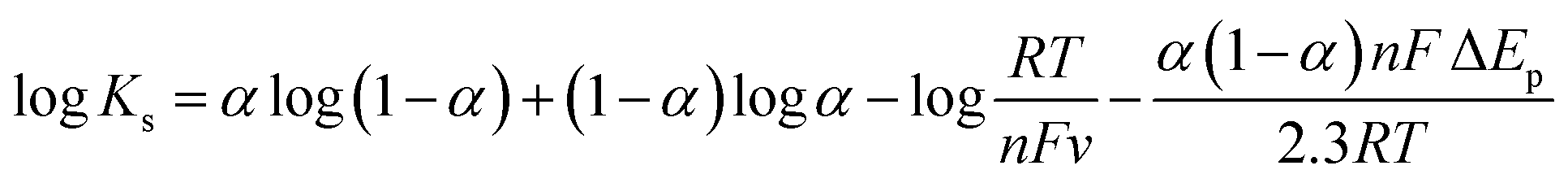 | (1) |
3.4 Electrocatalysis of the HRP/P-L-His-RGO modified film
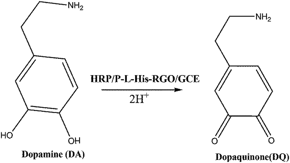
The electrocatalytic performances of the (a) bare GCE, (b) RGO/GCE, (c) P-L-His-RGO/GCE, and (d) HRP/P-L-His-RGO bio-nanocomposite were evaluated by recording the linear sweep voltammetry in 0.05 M PBS (pH 7.0) containing 3 mM DA at 50 mV s−1. It can be seen that there is an electrocatalytic reduction towards DA on the bare GCE and RGO/GCE exhibited by the lower peak current and higher over potential than that observed for the HRP/P-L-His-RGO bio-nanocomposite. Under the same conditions, the P-L-His-RGO/GCE modified electrode exhibits an Epa of DA with a more negative potential and with an enhanced peak current (Ipa) response greater than that of the bare GCE or RGO/GCE. This large decrease in oxidation over potential corresponds to the presence of high density arrays of P-L-His-RGO. Their electrocatalytic behaviour indicates that P-L-His-RGO significantly facilitates electron transfer with a negative potential shift. In addition, the catalytic activity of the HRP/P-L-His-RGO bio-nanocomposite (Fig. S3†) is evident from a decrease in the over potential as well as an increase in the response current for DA oxidation when compared with the bare GCE, RGO/GCE, and P-L-His-RGO/GCE modified electrodes. There is a two-fold increase in the oxidation peak current (Ipa) of DA on the HRP/P-L-His-RGO bio-nanocomposite over that of the other electrodes (bare GCE, RGO/GCE, and P-L-His-RGO/GCE). These experiments clearly indicate that the presence of P-L-His-RGO provided a favourable microenvironment that preserved HRP bioactivity and assisted the electron transfer process between the protein and the GCE electrode surface. This enhanced the signal and reduced the over potential for DA electrooxidation, both of which are very useful for practical applications in the fabrication of a sensitive and selective electrochemical DA sensor, with less risk of interference.The electrochemical catalytic oxidation of DA at the HRP/P-L-His-RGO/GCE modified electrode was investigated by linear sweep voltammetry. When DA was added to the PBS (pH 7.0) solution, a new oxidation peak appeared at about 0.2 V, as shown in Fig. 5A. The new peak originates from the oxidation of DA. The anodic peak current increased for each addition of DA into the buffer solution. The abovementioned experimental results demonstrate the good electrocatalytic activity of the HRP/P-L-His-RGO/GCE modified electrode towards the oxidation of DA. Thus, the HRP/P-L-His-RGO/GCE modified electrode showed greater sensitivity and faster catalytic activity towards DA. We only observed a 3% decrease in the initial response even after carrying out 50 continuous cyclic scans in the potential range of −0.1 to 0.4 V at a scan rate of 50 mV s−1, showing its high stability. The mechanism of the catalytic oxidation of the immobilized HRP on P-L-His-RGO/GCE modified electrode to DA is illustrated in the following scheme:55
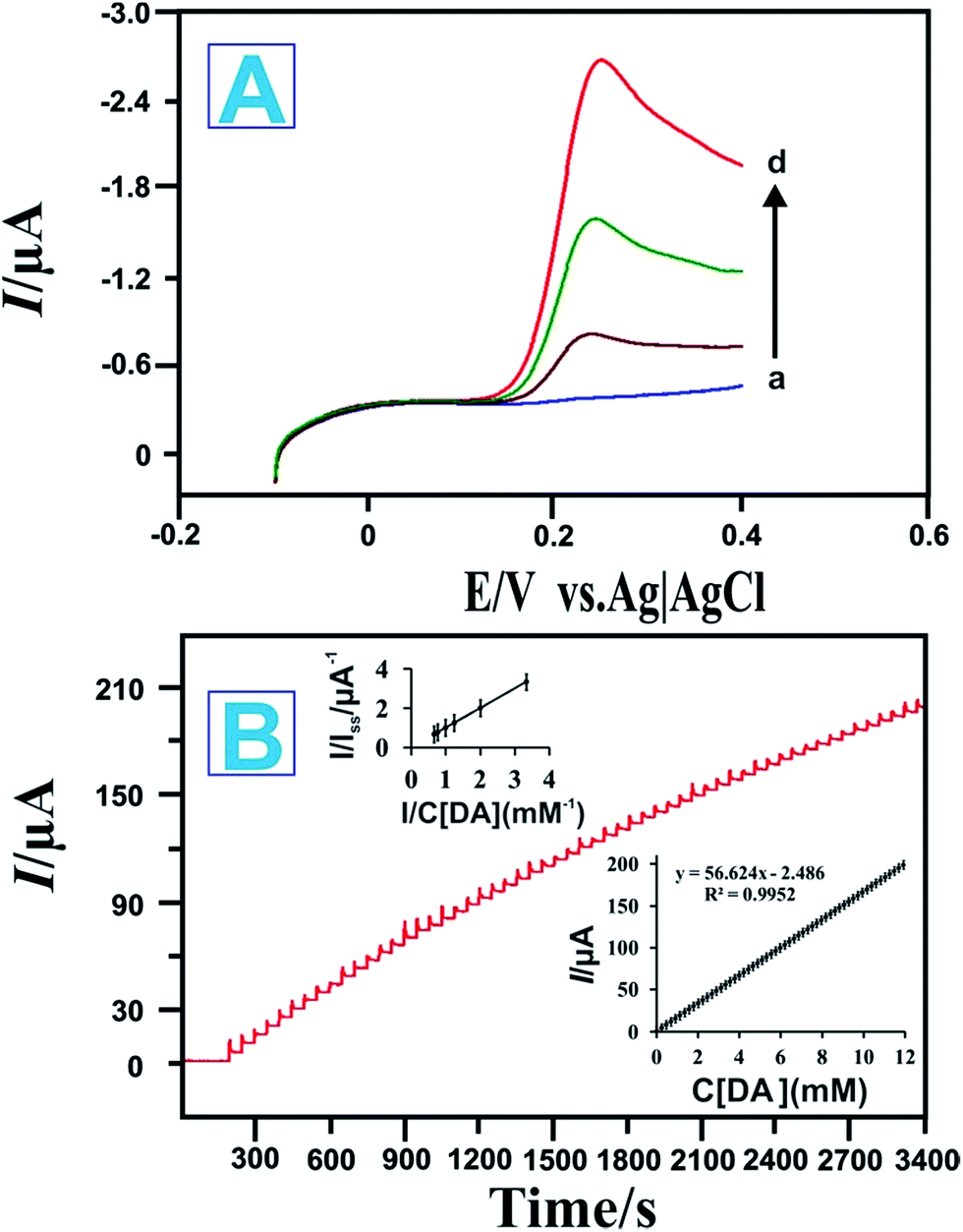 | ||
| Fig. 5 (A) Linear sweep voltammetry of the HRP-P-L-His-RGO modified GCEs electrode in PBS with DA concentrations of (a) blank, (b) 1, (c) 2, and (d) 3 mM. (B) Amperometric response of the fabricated biosensor to successive additions of DA into the PBS solution (0.05 M, pH 7). Applied potential: +0.23 V. Inset: calibration curve and linear fitting curve between the current and DA concentration. | ||
Fig. 5B illustrates a typical current-time plot obtained at the HRP/l-His-RGO modified rotating disc electrode for each successive addition of DA into the 0.05 M PBS (pH 7.0) solution. The electrode potential was held at +0.23 V vs. Ag/AgCl. When the background current became stable, a certain amount of DA was added into the solution and stirred at 1200 rpm. Fig. 5B shows that the amperometric peak current was linearly proportional to the concentration of DA. A stable and fast amperometric response could be observed for each successive injection of DA into the PBS solution. The time required to reach the steady state was less than 5 s, which indicates the rapid response of this sensor for DA. The inset to Fig. 5B shows the calibration plot for DA obtained over the concentration range of 0.2–12000 μM. The corresponding regression equations for the linear plot are expressed as follows:
| I(μA) = 56.624 + 2.486, R = 0.9952 | (2) |
The sensitivity of the sensor to DA was determined to be 16.2 μA mM−1 cm−2; and the detection limit was found to be 0.42 μM at a signal-to-noise ratio of 3. Further comparison of the HRP/P-L-His-RGO/GCE modified electrode developed in this study with other modified electrodes for the determinations of DA are listed in Table S1.† Because amperometry is more sensitive than cycle voltammetry, we used the amperometric method to determine the affinity of DA to the HRP/P-L-His-RGO/GCE modified electrode.
 | (3) |
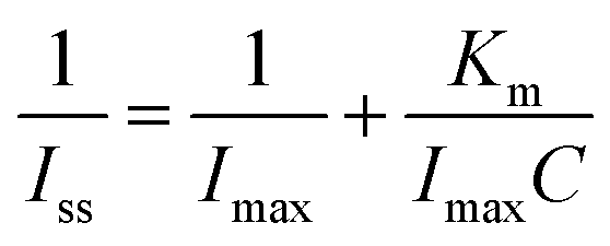
As shown in Fig. 5B, the apparent Michaelis–Menten constant (Km) can be obtained from the Lineweaver–Burk equation to evaluate the affinity of the immobilized enzyme towards DA.45 In this work, the Km of the HRP/P-L-His-RGO/GCE modified electrode was determined to be 2.5 mM. Thus, the P-L-His-RGO modified electrode has an improved affinity for the immobilization of HRP to DA. Evidently, the small Km value revealed the higher affinity of HRP/P-L-His-RGO/GCE for DA. Moreover, the selectivity of the DA biosensor was evaluated using the amperometric method. The results show that the common interfering species including 100 μM ascorbic acid, 100 μM glucose, 100 μM uric acid, and 100 μM cysteine did not cause any observable interference in the amperometric response to 100 μM DA at the HRP/P-L-His-RGO/GCE modified electrode. As shown in Fig. S5,† the prepared HRP/P-L-His-RGO/GCE modified electrode allowed high sensitivity and selectivity for DA detection under normal physiological conditions.
3.5 Electrocatalytic properties towards the reduction of H2O2
In order to investigate the electrocatalytic activity of the different electrodes: (a) bare GCE, (b) RGO modified GCE, (c) P-L-His modified GCE, (d) P-L-His-RGO modified GCE, and (e) HRP/P-L-His-RGO modified GCE towards the reduction of H2O2, CV was carried out in the presence of H2O2 at the HRP/P-L-His-RGO bio-nanocomposite modified GCE electrodes. Fig. S4† shows the CVs of 3 mM H2O2 in a pH 7 PBS buffer solution for the unmodified (a) bare GCE, (b) RGO modified GCE, (c) P-L-His modified GCE, (d) P-L-His-RGO modified GCE, and (e) HRP/P-L-His-RGO modified GCE electrodes. The results demonstrate the superior performance of the as-obtained HRP/P-L-His-RGO bio-nanocomposite. The HRP/P-L-His-RGO bio-nanocomposite modified GCE shows a greater background current than that of the other modified electrodes, which can be attributed to the large surface area of the P-L-His-RGO film. The nanostructures in this material provide a large surface area such that the composite P-L-His-RGO matrix has a higher capability for enzyme immobilization. Therefore, there was a two-fold increase in the reduction peak current of H2O2 at HRP/P-L-His-RGO modified GCE electrodes. These results show that the P-L-His-RGO modified GCE electrodes can improve the catalytic activity of HRP with more effective electrocatalytic activity toward H2O2 than the other modified electrodes.Fig. 6A shows the CVs of the HRP/P-L-His-RGO/GCE recorded in the presence of different concentrations of H2O2. The electrocatalytic responses of both the bare GCE and HRP/P-L-His-RGO/GCE towards the electrocatalytic reduction process of H2O2 have also been shown in Fig. 6A. However, no reduction peak was observed using the bare GCE. The intercalated HRP molecules produce good electrocatalytic activity due to the interactions between the HRP and the P-L-His-RGO/GCE.
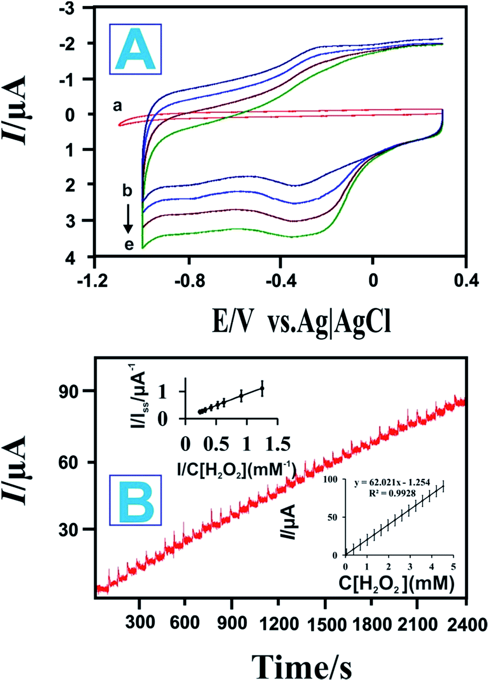 | ||
| Fig. 6 (A) Bioelectrocatalysis of the HRP/P-L-His-RGO modified GCEs towards H2O2 in PBS with a scan rate of 0.5 V s−1 and H2O2 concentrations of (a) are GCE, (b) blank, (c) 1, (d) 2, and (e) 3 mM. (B) Typical current-time response curves for the HRP/P-L-His-RGO modified GCEs after successive additions of H2O2 into pH 7 PBS. Applied potential: −0.2 V (vs. Ag/AgCl). Inset: calibration curve showing variation of the biosensor response with H2O2 concentration. | ||
It is evident that the reduction current of H2O2 increased when increasing the H2O2 concentrations from 1 mM to 3 mM. These observations clearly indicate that the HRP/P-L-His-RGO/GCE exhibits excellent catalytic activity towards the reduction of H2O2. The electrocatalytic process can be expressed as follows:27,46,57
| HRP (Fe3+) + H2O2 → Compound I (Fe4+ = O) + H2O | (4) |
| Compound I (Fe4+ = O) + e− + H+ → Compound II | (5) |
| Compound II + e− + H+ → HRP (Fe3+) + H2O | (6) |
The overall reaction would be:
| H2O2 + 2e− + 2H+ → 2H2O | (7) |
We then investigated the amperometric response of the HRP/P-L-His-RGO/GCE modified rotating disc electrode towards each successive addition of H2O2 into 0.05 M PBS (pH 7.0) at an applied potential of −0.2 V as shown in Fig. 6B. Upon addition of aliquots of H2O2 into the 0.05 M PBS (pH 7.0) solution, the prepared HRP/P-L-His-RGO/GCE sensor responded rapidly and achieved the maximum steady-state current within 5 s. As shown in Fig. 6B a linear dependence of the peak current with the concentration of H2O2 was observed in the range of 0.2 to 5000 μM with a sensitivity of 266.4 mA mM−1 cm−2. The detection limit was estimated to be 0.05 μM at a signal-to-noise ratio of 3. The electrocatalytic efficiency of the proposed HRP/P-L-His-RGO/GCE electrode for the determination of H2O2 was compared with other types of HRP modified electrodes as shown in Table 1. The apparent Michaelis–Menten constant (Km), which is an indicator of the enzyme-substrate kinetics was calculated from the Lineweaver–Burk equation, where Iss is the steady-state current attained after the addition of the substrate, Imax is the maximum current measured under saturated substrate conditions and C is the bulk concentration of the substrate. The Km value was found to be 1.2 mM, which suggests an apparent affinity between immobilized HRP and L-His-RGO/GCE. Furthermore, the effect of possible interfering species, such as uric acid (UA), glucose (Glu), and ascorbic acid (AA), on H2O2 detection was also investigated. The amperometric responses of the HRP/l-His-RGO/GCE to the continuous addition of 100 μM UA, 100 μM AA, 100 μM glucose and 100 μM H2O2 at working potentials of −0.2 V in PBS (0.05 M, pH 7.0) were studied. As shown in Fig. S6† there is clear indication that the interference from UA or AA is negligible at an applied potential of −0.2 V.
| Modified electrodes | Linear range μM | Sensitivity mA mM−1 cm−2 | LOD μM | Ref. |
|---|---|---|---|---|
| Au/graphene sheet/HRP/chitosan | 5–5130 | — | 1.7 | 27 |
| Sonogel-carbon electrode/HRP | 4.0–100 | 12.8 | 1.6 | 45 |
| MWNT–silica–polyaniline–NW–HRP | 1 × 10⁻⁶–1000 | 58.1 | 1 × 10⁻⁶ | 47 |
| GCE/silica–hydroxyapatite/HRP | 1–100 | 0.051 | 0.35 | 56 |
| HRP–Nafion-screen printed electrode | 5.98–35.36 | 0.143 | 0.48 | 58 |
| ZnO/GNPs/Nafion/HRP | 15–1100 | — | 9 | 59 |
| Clay/HRP/Au/CS | 39–3100 | — | 9 | 60 |
| Au/CS/HRP | 12.2–2430 | 0.013 | 6.3 | 61 |
| CMCS/Au/HRP | 5–1400 | — | 0.401 | 62 |
| HRP–ZrO2/Au | 20–9450 | — | 2 | 63 |
| HRP/P-L-His-RGO/GCE | 0.2–5000 | 266.4 | 0.05 | This work |
3.6 Real sample analysis
We investigated the response of the HRP/P-L-His-RGO/GCE biosensor for the measurement of H2O2 in real eye drop samples. The eye drop sample was obtained from a pharmacy. 1 mL of the sample was dissolved in PBS (pH 7) prior to measurement. The analytical applicability of the HRP/P-L-His-RGO/GCE biosensor was evaluated by determining the recovery towards different concentrations of hydrogen peroxide using the standard addition method. The obtained results are given in Table 2, which indicate that this method is reliable and could be effectively used in future applications. We further explored the practicality of the proposed HRP/P-L-His-RGO/GCE biosensor for the determination of DA in human urine and serum samples. Sampling was performed using the standard additional method. All the urine and serum samples (1 mL) were dissolved in PBS (pH 7) prior to use. The analytical results are shown in Table S2.† These results indicate the effectiveness of this method for practical applications.| Samples | Added [μM] | Found [μM] | Recovery rate (%) |
|---|---|---|---|
| 1 | 5 | 4.8 | 101% |
| 2 | 10 | 9.6 | 99.5% |
| 3 | 20 | 18.2 | 98% |
3.7 Stability and reproducibility of the sensor
The as-prepared HRP/P-L-His-RGO/GCE modified electrode showed an acceptable reproducibility with a relative standard deviation of 3.6% for the current determined at a DA concentration of 50 μM. The reproducibility of the different modified electrodes was also examined. Compared with the HRP/P-L-His-RGO/GCE, only RGO and P-L-His-RGO films have an RSD of 3.22% and 4.22%, respectively. In addition, the stability of the HRP/P-L-His-RGO/GCE modified electrode was evaluated after being stored in 0.05 M PBS (pH 7.0) at 4 °C. The storage stability was evaluated by periodically checking its relative response current in PBS containing 50 μM of DA. After a storage period of 20 days, the HRP/P-L-His-RGO/GCE modified electrode showed an 8% loss of activity. Thus, the good repeatability, reproducibility and selectivity of the developed biosensor make it attractive for practical applications.4. Conclusions
In summary, a biocompatible nanocomposite electrode based on HRP/P-L-His-RGO film was proposed for the determination of H2O2 and DA. We have demonstrated the feasibility of this novel design for an enzymatic electrochemical H2O2 and DA sensor based on a HRP/P-L-His-RGO/GCE modified electrode. The as-prepared HRP/P-L-His-RGO/GCE modified electrode exhibited very strong and sensitive amperometric responses to H2O2 and DA. The ease of fabrication, fast response and high sensitivity and long stability show the potential of the enzymatic H2O2 and DA sensor, proposed in this study, for the detection of H2O2 and DA in real clinical and wastewater samples. The HRP/P-L-His-RGO/GCE modified electrode provides a promising platform for the design of reagent-less biosensors owing to the advantages of simplicity, rapidity and ease of operation.Acknowledgements
The authors gratefully acknowledge the financial support received from the Ministry of Science and Technology, Taiwan (ROC).References
- M. Zhang, C. Liao, Y. Yao, Z. Liu, F. Gong and F. Yan, Adv. Funct. Mater., 2014, 24, 978–985 CrossRef CAS.
- M. Rajkumar, B. Devadas, S. Chen and P. Yeh, Colloids Surf., A, 2014, 452, 39–45 CrossRef CAS.
- S. Palanisamy, S. Ku and S. Chen, Electrochim. Acta, 2013, 180, 1037–1042 CAS.
- U. Chandra, B. E. Kumara Swamy, O. Gilbert and B. S. Sherigara, Electrochim. Acta, 2010, 55, 7166 CrossRef CAS.
- J. H. Jin, E. Cho and S. Jung, Biotechnol. Lett., 2010, 32, 413 CrossRef CAS PubMed.
- R. Suresh, K. Giribabu, R. Manigandan, S. Praveen Kumar, S. Munusamy, S. Muthamizh, A. Stephen and V. Narayanan, Sens. Actuators, B, 2014, 202, 440–447 CrossRef CAS.
- Y. Wu, L. Cui, Y. Liu, G. Lv, T. Pu, D. Liu and X. He, Analyst, 2013, 138, 1204–1211 RSC.
- Q. M. Li, J. Li and Z. J. Yang, Anal. Chim. Acta, 2007, 583, 147–152 CrossRef CAS PubMed.
- Z. H. Guo and S. J. Dong, Electroanalysis, 2005, 17, 607 CrossRef CAS.
- S. Sarre, Y. Michotle, P. Herregodts, D. Deleu, N. De Klippel and G. Ebinger, J. Chromatogr., 1992, 585, 207 CrossRef.
- S. Thiagarajan, R. Yang and S. Chen, Bioelectrochemistry, 2009, 75, 163–169 CrossRef CAS PubMed.
- Y. Wang, Y. Li, L. Tang, J. Lu and J. Li, Electrochem. Commun., 2009, 11, 889–892 CrossRef CAS.
- M. Rajkumar, B. Devadas and S. Chen, Electrochim. Acta, 2013, 105, 439–446 CrossRef CAS.
- S. Liu, B. Yu and T. Zhang, RSC Adv., 2014, 4, 544–548 RSC.
- B. Yu, J. Feng, S. Liu and T. Zhang, RSC Adv., 2013, 3, 14303–14307 RSC.
- Q. Lu, X. Dong, L. Li and X. Hu, Talanta, 2010, 82, 1344–1348 CrossRef CAS PubMed.
- E. Ferapontova, K. Schmengler, T. Borchers, T. Ruzgas and L. Gorton, Biosens. Bioelectron., 2002, 17, 953–963 CrossRef CAS PubMed.
- K. Nakashima, K. Maki, S. Kawaguchi, S. Akiyama, Y. Tsukamoto and K. Imai, Anal. Sci., 1991, 7, 709–713 CrossRef CAS.
- C. Matsubara, N. Kawamoto and K. Takamala, Analyst, 1992, 117, 1781–1784 RSC.
- E. C. Hurdis and J. H. Romeyn, Anal. Chem., 1954, 26, 320–325 CrossRef CAS.
- S. Liu, J. Tian, L. Wang and X. Sun, Carbon, 2011, 49, 3158–3164 CrossRef CAS.
- S. Liu, J. Tian, L. Wang, H. Li, Y. Zhang and X. Sun, Macromolecules, 2010, 43, 10078–10083 CrossRef CAS.
- J. L. Huang and Y. C. Tsai, Sens. Actuators, B, 2009, 140, 267–272 CrossRef CAS.
- H. L. Zhang, G. S. Lai, D. Y. Han and A. M. Yu, Anal. Bioanal. Chem., 2008, 390, 971–977 CrossRef CAS PubMed.
- B. Liu, Z. Liu, D. Chen, J. Kong and J. Deng, J. Anal. Chem., 2000, 367, 539–544 CAS.
- D. F. Cao, P. L. He and N. F. Hu, Analyst, 2003, 128, 1268–1274 RSC.
- K. F. Zhou, Y. H. Zhu, X. L. Yang, J. Luo, C. Z. Li and S. R. Luan, Electrochim. Acta, 2010, 55, 3055–3060 CrossRef CAS.
- Y. Xiao, H. X. Ju and H. Y. Chen, Anal. Biochem., 2000, 278, 22–28 CrossRef PubMed.
- B. Utpal, S. Pragya, K. Krishnamoorthy and N. Pradip, Journal of Biotechnology, 2006, 126, 220–229 CrossRef PubMed.
- S. Qu, F. Huang, G. Chen, S. N. Yu and J. L. Kong, Electrochem. Commun., 2007, 9, 2812–2816 CrossRef CAS.
- J. W. Wang, M. Gu, J. W. Di, Y. S. Gao, Y. Wu and Y. F. Tu, Bioprocess Biosyst. Eng., 2007, 30, 289–296 CrossRef CAS PubMed.
- A. Morrin, F. Wilbeer, O. Ngamma, S. E. Moulton, A. J. Killard, G. G. Wallace and M. R. Smyth, Electrochem. Commun., 2005, 7, 317–322 CrossRef CAS.
- K. S. Novoselov, Science, 2004, 306, 666–669 CrossRef CAS PubMed.
- P. Avouris, Z. H. Chen and V. Perebeinos, Nat. Nanotechnol., 2007, 2, 605–615 CrossRef CAS PubMed.
- A. K. Geim and K. S. Novoselov, Nat. Mater., 2007, 6, 183–191 CrossRef CAS PubMed.
- A. N. Cao, Z. Liu, S. S. Chu, M. H. Wu, Z. M. Ye, Z. W. Cai, Y. L. Chang, S. F. Wang, Q. H. Gong and Y. F. Liu, Adv. Mater., 2010, 22, 103–106 CrossRef CAS PubMed.
- E. Yoo, T. Okata, T. Akita, M. Kohyama, J. Nakamura and I. Honma, Nano Lett., 2009, 9, 2255–2259 CrossRef CAS PubMed.
- H. Bai, C. Li and G. Q. Shi, Adv. Mater., 2011, 23, 1089–1115 CrossRef CAS PubMed.
- M. Zhou and S. Dong, Acc. Chem. Res., 2011, 44, 1232–1243 CrossRef CAS PubMed.
- M. Zhou, Y. Zhai and S. Dong, Anal. Chem., 2009, 81, 5603–5613 CrossRef CAS PubMed.
- W. S. Hummers and R. E. Offeman, J. Am. Chem. Soc., 1958, 80, 1339–1339 CrossRef CAS.
- Z. Liu, X. Duan, G. Qian, X. Zhou and W. Yuan, Nanotechnology, 2013, 24, 1–6 Search PubMed.
- L. Wang, Y. Ye, X. Lu, Z. Wen, Z. Li, H. Hou and Y. Song, Sci. Rep., 2013, 3568, 1–9 Search PubMed.
- C. Guo, X. Zheng, S. Ng, Y. Lai, Y. Lei and C. Li, Chem. Commun., 2011, 47, 2652–2654 RSC.
- M. ElKaoutit, I. Naranjo-Rodriguez, M. Dominguez, M. P. Hernandez-Artiga and D. Bellido-Milla, Electrochim. Acta, 2008, 53, 7131–7137 CrossRef CAS.
- A. Periasamy, S. Yang and S. Chen, Talanta, 2011, 87, 15–23 CrossRef CAS PubMed.
- S. Komathi, A. Gopalan, S. Kim, G. Anand and K. Lee, Electrochim. Acta, 2013, 92, 71–78 CrossRef CAS.
- L. Wan, Y. Song, H. Zhu, Y. Wang and L. Wang, Int. J. Electrochem. Sci., 2011, 6, 4700–4713 CAS.
- B. Wang, J. J. Zhang, Z. Y. Pan, X. Q. Tao and H. S. Wang, Biosens. Bioelectron., 2009, 24, 1141–1145 CrossRef CAS PubMed.
- E. Laviron, J. Electroanal. Chem., 1979, 101, 19–28 CrossRef CAS.
- X. Chen, C. Ruan, J. Kong and J. Deng, Anal. Chim. Acta, 2000, 412, 89–98 CrossRef CAS.
- X. Kang, J. Wang, Z. Tang, H. Wu and Y. Lin, Talanta, 2009, 78, 120–125 CrossRef CAS PubMed.
- A. Lindgren, T. Ruzgas, L. Gorton, E. Csoregi, G. Bautista Ardila, I. Y. Sakharov and I. G. Gazaryan, Biosens. Bioelectron., 2000, 15, 491–497 CrossRef CAS PubMed.
- T. Tatsuma, K. Ariyama and N. Oyama, J. Electroanal. Chem., 1998, 446, 205–209 CrossRef CAS.
- P. Raghu, T. Madhusudana Reddy, P. Gopal, K. Reddaiah and N. Y. Sreedhar, Enzyme Microb. Technol., 2014, 57, 8–15 CrossRef CAS PubMed.
- B. Wang, J. J. Zhang, Z. Y. Pan, X. Q. Tao and H. S. Wang, Biosens. Bioelectron., 2009, 24, 1141–1145 CrossRef CAS PubMed.
- L. Qian and X. Yang, Talanta, 2006, 68, 721–727 CrossRef CAS PubMed.
- Y. J. Teng, S. H. Zuo and M. B. Lan, Biosens. Bioelectron., 2009, 24, 1353–1357 CrossRef CAS PubMed.
- C. Xiang, Y. Zou, L. Sun and F. Xu, Sens. Actuators, B, 2009, 136, 158–162 CrossRef CAS.
- X. Zhao, Z. Mai, X. Kang and X. Zou, Biosens. Bioelectron., 2008, 23, 1032–1038 CrossRef CAS PubMed.
- C. Lei, S. Hu, G. Shen and R. Yu, Talanta, 2003, 59, 981–988 CrossRef CAS PubMed.
- Q. Xu, C. Mao, N. Liu, J. Zhua and J. Sheng, Biosens. Bioelectron., 2006, 22, 768–773 CrossRef CAS PubMed.
- Z. Tong, R. Yuan, Y. Chai, Y. Xie and S. Chen, J. Biotechnol., 2007, 128, 567–575 CrossRef CAS PubMed.
Footnote |
| † Electronic supplementary information (ESI) available. See DOI: 10.1039/c4ra09011j |
| This journal is © The Royal Society of Chemistry 2014 |