Wen Qiaoa,
Shiming Yanab,
Xuemin Hea,
Xueyin Songa,
Zhiwen Lia,
Xing Zhanga,
Wei Zhong*a and
Youwei Dua
aNational Laboratory of Solid State Microstructures, Department of Physics, Nanjing University, Nanjing 210093, People's Republic of China. E-mail: wzhong@nju.edu.cn
bCollege of Science, Henan University of Technology, Zhengzhou 450001, People's Republic of China
First published on 25th September 2014
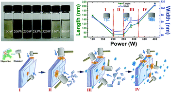
Liquid exfoliation has been widely used to yield two dimensional layered materials in laboratory because of its simplicity and ease for mass production characteristics. In this study, the dispersions and morphology of exfoliated MoS2 in N-methyl-2-pyrrolidone (NMP) solvent at different ultrasonic powers are investigated. An optimal power to exfoliate MoS2 nanoflakes in NMP for high yield and small lateral size with narrow size distribution is obtained. Our results showed that the concentration of dispersions did not monotonously increase with growing ultrasonic power, but rather initially increased with input power, and then decreased after 320 W due to the cavitation shielding effect. The flake size decreased with ultrasonic power from 100 W to 250 W and then slightly increased; after 320 W, the average lateral size of flakes dramatically increased and a wide size distribution with relatively large scale nano-flakes was detected. The mechanism of ultrasonic cavitation effect on the concentration and morphology has been analyzed.
Some approaches to obtain few-layered or monolayered MoS2 have been reported. Original methods utilized to produce MoS2 nanosheets involve micromechanical exfoliation13,16 and lithium intercalation exfoliation.8,14,17 Mechanical cleavage can obtain isolated individual crystal planes (monolayers) with high crystal quality and macroscopic continuity. However, this method can achieve exfoliation only on a small scale. In comparison, the lithium intercalation method tends to give the sizable quantities of MoS2 monolayers and its sensitive nature has been recently overcome by ammonia intercalation reported by Anto Jeffery et al.18 however, it is time-consuming and introduces a phase transformation of MoS2 from 2H to 1T with Li intercalation.14,17 Other approaches that are being explored include chemical vapor deposition (CVD) synthesis19–21 and liquid exfoliation.22–25 CVD is a good synthesis method that gives better control over the number of layers and large-area growth. Nevertheless, it requires high-temperature annealing conditions and an improved quality of synthesized MoS2. The liquid exfoliation of layered materials has been found to have great potential for the scalable production of two-dimensional (2D) nanosheet-based materials, such as 2D nanosheet suspensions, thin films and 2D nanosheet-based hybrids and composites.22–25 Coleman et al. have shown that layered materials such as MoS2, WS2, and BN can be exfoliated to monolayer and few-layer 2D nanosheets in various organic solvents22,25 or aqueous surfactant solutions via sonication.23
Liquid exfoliation needs to expose the layered material to ultrasonic waves in a solvent. Such waves generate cavitation bubbles that collapse into high-energy jets, breaking up the layered crystallites and producing exfoliated nanosheets. Ultrasonication has been widely used for the exfoliation and dispersion of nano-materials,22–27 sonochemical synthesis, ultrasonic cleaning, and lithotripsy.28–31 In particular, it has been utilized in the production of two-dimensional materials from bulk-layered crystal materials in liquid.22–27,32,33 During the ultrasonic processing, the propagation of high amplitude ultrasonic waves leads to the creation of voids and rapid formation of cavities (bubbles). These bubbles grow in the zone of negative pressure of the acoustic field, while they shrink in the zone of positive pressure. Continuous interaction between the bubbles and the acoustic field causes the growth and ultimately a violent collapse of the bubbles. The implosion of bubbles can create high-speed jets and intense shock-waves on the surface of bulk materials.34
The previous works on liquid exfoliation of layered materials were mainly focused on the effects of solvent selection,22,25 sonic time, centrifugal rate, and initial concentration on exfoliation efficiency,23,24 while few researchers have paid attention to the influences of cavitation intensity induced by the ultrasonication on the exfoliation efficiency.23,27,35 Although it is clear that the acoustic cavitation plays a critical role in the exfoliation and dispersion, it is often neglected in previous works. Because the input power of the device is a significant parameter to characterize cavitation, thus in this work, we investigate the influence of different input powers on the dispersion concentration, morphology and photoluminescence (PL) of layered MoS2.
To estimate the concentration, the scattering background is extrapolated from the high-wavelength region (dash line in the inset of Fig. 1(a)), and the value of A/l solely because resonant absorption is estimated for each sample (about 674 nm, illustrated by A peaks in Fig. 1(a)). In most of the cases, this allows us to determine the concentration of MoS2 dispersions, regardless of the value of the scattering exponent. The concentration of dispersed material can be semi-quantitatively determined by A/l subtracted background provided the absorption coefficient, α, is known.24 The A/l values subtracted by the scattering background as a function of input power are presented in Fig. 1(b). It can be seen that the dispersion concentration initially increases with ultrasonic power, and then sharply decreases after 320 W, which completely coincide with the photograph of suspensions of MoS2 in NMP at various power intensities, as shown in Fig. 1(d). The color of the final dispersions evidently varies with different powers, indicating that the concentrations of the nanosheets have indeed changed. This difference can be largely attributed to the ultrasonic cavitation effect. For a general liquid, the cavitation intensity initially increases with increasing ultrasonic power; however, it tends to maximize when the ultrasonic intensity reaches a certain value. The cavitation intensity decreases with further increasing input power. This is because a large number of vain bubbles generated from the increased ultrasonic power would increase the scattering attenuation and reduce the cavitation intensity.38 A detailed discussion about the cavitation effects on the production of MoS2 nanoflakes is presented in Fig. 4.
In addition, these spectra appear to be superimposed on a power law background in the inset of Fig. 1(a). The low-energy non-resonant region appears almost linear confirming the light scattering (∝λ−n).22,24 The scattering exponent, n, is estimated from the high wavelength region, as plotted in Fig. 1(c). It is clear that the scattering exponent, n, is not a constant, but increases from n = 3.5 to n = 3.9 as the ultrasonic power increases from 100 W to 200 W, and then decreases to n = 2.7 as the ultrasonic power further increases to 400 W, suggesting a variation in flake size. The scattering exponent is close to 4.0 from 200 W to 320 W. This might be expected for Rayleigh scattering,24 which would be consistent with the small lateral size of nanosheets. In addition, the scattering exponent decreases with further increasing power, indicating the increase of flake size. A similar trend is observed at the variation of A excitonic peak position, which indicates the change of nanoflakes size, as shown in the inset of Fig. 1(c). The blue shift of A peaks shows that the flakes have relatively smaller dimension.39
Transmission electron microscopy (TEM) was performed on each sample to determine the quality and dimensions of the flakes. Generally, the flakes appear to be well-exfoliated (Fig. 2) with some very thin sheets, including the monolayers (as shown in the inset of Fig. 2(a)). A further examination of flake quality was performed by obtaining selected area electron diffraction (SAED) pattern (Fig. 2(b)) and high resolution TEM (HRTEM) images (Fig. 2(c) and (d)). Fig. 2(b) presents the SAED pattern taken from the MoS2 flakes selected in Fig. 2(a) represented by the black circle. The SAED pattern indicates the single crystalline nature and an undistorted lattice of the nanoflakes. The high resolution images in Fig. 2(c) and (d) show clean and well-defined hexagonal symmetric structures. The d100 is 2.7 Å and d110 is 1.6 Å. These images indicate that high power intensity did not damage or disrupt the hexagonal structure of MoS2.
Fig. 3 displays the TEM micrographs of different samples, suggesting that the MoS2 is well-exfoliated below 320 W. The size of the flakes could be readily determined from large-scale TEM micrographs. As shown in Fig. 4(b), the flakes prepared at 100 W have a mean length 〈L〉 ≈ 157 nm and width 〈W〉 ≈ 75 nm. As the power increased, the flake sizes decreased, reaching 〈L〉 ≈ 72 nm and 〈W〉 ≈ 33 nm for the 250 W sample. However, the flake sizes increased after 250 W, reaching 〈L〉 ≈ 124 nm and 〈W〉 ≈ 63 nm for the 320 W sample, which further increased to 〈L〉 ≈ 207 nm and 〈W〉 ≈ 112 nm for the 400 W sample.
![]() | ||
Fig. 3 (a) to (d) Typical bright field TEM images of MoS2 nanoflakes prepared with 100, 250, 320 and 400 W, respectively. |
This variation is mainly associated with the ultrasonic cavitation effect. It is generally known that there are two types of acoustic cavitation in liquid, as shown in Fig. 4(a). Stable cavitation (top in Fig. 4(a)) is typically generated at low acoustic fields, whereas bubbles have a long growth cycle and undergo multiple oscillations at the equilibrium position.40 When the resonance frequency of bubbles corresponds with that of sound waves, the maximum energy coupling of acoustic field and bubbles will be generated, accompanying an obvious cavitation effect. In contrast to stable cavitation, inertial cavitation (bottom in Fig. 4(a)) will occur when the ultrasonic power further increases, whereas bubbles oscillate and ultimately chaotically collapse within a few sound wave cycles, thus producing extremely high fluid acceleration and broadband noise.41 Fig. 4(c) shows the schematic representation of the exfoliation procedure at different input powers during which the high speed liquid jet is compared to a hammer knocking on the right and profile side of the bulk material. At low input power (Fig. 4(c), I), corresponding to the stable cavitation, the knocking on the right side has little ability to destroy the covalently bonded S–Mo–S, while the knocking profile can easily overcome van der Waals forces holding between sheets. Thus large sizes of MoS2 flakes are produced in this region. Decrease in the size of the flake with increasing input power is explained by the inertial cavitation, which has the ability to destroy the covalently bonded S–Mo–S and knock the sheets into small flakes along the defects generated by the continuously high intensity knocking on the surface, as shown in (Fig. 4(c), II). The strongest cavitation effect emerges in the range from 200 W to 250 W, and it produces the smallest size nanoflakes with narrow lateral size distribution. This effect is analogous to the results, which states that the flakes could be cut by the scission of low-energy ball milling and sonication as observed previously for MoS2 dispersions.42 It has the same mechanism in the range of 285 W to 320 W. The increase in the number of cavitation bubbles leads to a high yield of nanoflakes. However, at the same time a small amount of vain bubbles are generated, weakening the knocking intensity and leading to a slight increase in the size of the nanoflakes (Fig. 4(c), III). For the 400 W sample (Fig. 4(c), IV), the flake dimensions reach to the maximum. This is because of the ultrasonic cavitation shielding effect, where the increasing population of bubbles beneath the tip hinders the transmission of acoustic waves and generation of inertial cavitation,38 resulting in the less efficient exfoliation of MoS2. The photographs of cavitation bubbles in Fig. 4(d) are in accordance with the analysis that is discussed above. An obvious transformation from stable cavitation to inertial cavitation can be observed from the bubbles that are shown in the images of 100 W and 200 W. At powers greater than 285 W, the number of vain bubbles increases with increasing power intensity. Fig. 4(e) displays the SEM images of MoS2 sediments dried at 60 °C after the first centrifugation. The size and morphology of these sediments are also largely consistent with our analysis.
Tapping mode atomic force microscopy (AFM) is used for assessing the thicknesses of these 2D MoS2 layers prepared at different powers. As shown in Fig. 5(a), (c) and (e), a clear step of ∼3.4, 2.7, and 4.4 and 1.4 nm are observed in typical 2D liquid-exfoliated MoS2 flakes, respectively. It is also seen that the 2D nanoflakes display various thickness distributions, but the majority of thickness range from 3–7 nm, 1–5 nm and 2–10 nm for 100, 250 and 400 W MoS2 samples (as shown in Fig. 5(b), (d) and (f)), respectively, indicating the presence of monolayers in effective exfoliation samples.
Because the lateral dimensions of these MoS2 nanoflakes are mostly smaller than 100 nm, their PL properties are expected to be different from those of samples with relatively larger lateral dimensions (generally larger than 1 μm). The PL spectra of these nanoflakes are measured using fluorescence spectroscopy at different excitation wavelengths ranging from 325 to 500 nm to provide a comprehensive view of the PL properties of the MoS2 nanoflakes. Fig. 6(a) and (c) show the PL spectra of 2D MoS2 nanoflakes prepared at 250 W and 400 W, respectively. For the excitation wavelength of 375 nm, both the samples show a strong luminescence peak centered at ∼477 nm and 485 nm, respectively. The luminescence becomes less significant at 500 nm excitation wavelengths for both the samples. This result is consistent with those of MoS2 quantum dots and low-dimensional liquid exfoliated MoS2 flakes.35,37,39,43,44
A less substantial red shift is noticed in the PL spectra of 250 W sample (Fig. 6(a)) when the excitation wavelength increases from 325 nm to 500 nm, which may be ascribed to the narrow lateral size distribution. As shown in Fig. 6(b), the main lateral dimension ranges from 15 to 35 nm and the full width at half maximum (FWHM) is 34 nm given by Gauss fitting. However, a clear red shift in the PL spectra of 400 W sample (Fig. 6(c)) is observed with the increase of the excitation wavelength, which is similar to several recent results.35,37,39,44 Compared to the 250 W sample, there are wide lateral size distributions ranging from 20 to 120 nm (FWHM is 88 nm) for the 400 W sample (Fig. 6(d)). It is suggested that the excitation dependent PL could be related to the polydispersity of 2D MoS2 nanoflakes, for which the emission wavelength of the PL is a strong function of the lateral dimension of the quasi-2D nanoflakes due to the quantum size effect.44
This journal is © The Royal Society of Chemistry 2014 |