DOI:
10.1039/C4RA08536A
(Paper)
RSC Adv., 2014,
4, 49595-49604
Retracted Article: Multi-walled carbon nanotubes decorated with palladium nanoparticles as a novel platform for electrocatalytic sensing applications
Received
12th August 2014
, Accepted 18th September 2014
First published on 18th September 2014
Abstract
A simple method is described for decorating multi-walled carbon nanotubes (MWCNTs) with palladium nanoparticles (PdNPs). MWCNTs were functionalized via a C–C covalent bond with metformin (Met/fMWCNT). The subsequent bonding of the imine groups with palladium offered strong adhesion of PdNPs on functionalized MWCNT surface (Pd@Met/fMWCNT). The structure and morphology of the resulting MWCNT-based nanocomposite were characterized by transmission electron microscopy, X-ray diffraction and FT-IR. Pd@Met/fMWCNT nanocomposite was used to immobilize glucose oxidase (GOx) on glassy carbon electrode. Detailed electrochemical analysis was performed and it was found that Pd@Met/fMWCNT nanocomposite significantly improved direct electron transfer between GOx and glassy carbon electrode, leading to fabrication of a potential biosensor offering very sensitive detection of glucose. The surface coverage of GOx and the electron transfer rate constant (ks) were calculated to be 4.17 × 10⁻¹⁰ mol cm−2 and 3.24 s−1, respectively. The apparent Michaelis–Menten constant of the immobilized GOx was 0.48 mM, implying a strong catalytic activity and a remarkable affinity of the immobilized GOx for glucose. The linear detection range of glucose was 4.0–1500 μM, with a detection limit of 1.4 ± 0.04 μM.
1. Introduction
In recent decades, great efforts have been directed towards improving molecular sensing or recognizing systems for chemically and biologically important molecules.1−6 Electrochemical biosensors, capable of direct transduction of a biomolecular recognition event into an electronic signal, with lower detection limits are of interest for sensitive and specific detection of target analytes.7 However, development of a biosensor with improved parameters such as selectivity and stability, which depend on the biosensing molecule attachment and its compatibility with the solid surface, requires extensive investigation.8,9 Recently, biosensors have been developed using carbon nanotubes (CNTs) and electrochemical techniques,10 where CNTs allow binding of biomolecules in the close vicinity of the electrode surface, and the electrochemical detection technique results in enhanced sensitivity, fast response, low cost, and portability.11,12 Moreover, the high conductivity and charge transfer channels of CNTs make them a promising material for biomolecular immobilization applications.13,14 In recent years, MWCNTs have been one of the most intensively investigated nanostructured materials.15 Chemical functionalization of MWCNTs can enhance specific surface area and thereby improve electrical conductivity, mechanical properties and compatibility for immobilization of biomolecules.16,17 The subtle properties of functionalized MWCNTs render them very attractive candidates for use as nanotemplates for dispersion and stabilization of nanomaterials. Metal nanoparticles with well-defined surfaces have attracted significant attention in many research areas, because of their extraordinary catalytic, magnetic and optical properties.18,19 Generally, the electrocatalytic activity of metal nanoparticles depends on the nature, generation, size and kind of the functional groups available on the support.18,20−22 Several methods have been developed to attach metal nanoparticles to CNTs. Yu et al. showed that deposition of well-dispersed Pt as small metal clusters (10–20 nm) onto functionalized carbon nanotubes can be achieved when nanotubes were previously oxidized by HNO3 or H2SO4–HNO3 mixture;23 Sun et al. reported an approach with highly dispersed Pd nanoparticles on covalent functional MWCNT surfaces;22 Zanella et al. reported deposition of gold nanoparticles onto thiol-functionalized MWCNTs.24
Determination of glucose is important in biological fluids, such as blood and urine, for diagnosis and treatment of diabetic patients.25 As is well known, diabetes is a worldwide public health problem.26 Reagentless glucose biosensors based on the direct electrochemistry of glucose oxidase (GOx) are used in monitoring of serum or urine glucose levels.27 However, the two bound redox-active flavin adenine dinucleotide cofactors of GOx are deeply buried within the insulated prosthetic shells, rendering them inaccessible for direct electron transfer (DET) with bare electrodes.27 Intensive efforts have been devoted to promoting retention of the biological activity and the DET behaviors of GOx via selected matrixes.27−31 For use as a biosensor platform, such matrixes not only must present an abundant domain for biomolecular binding but also fast electron transfer of enzyme and further amplification of the electrochemical signal.
In the present work, synthesis of a novel nanocomposite based on heterogeneous palladium nanoparticles (PdNPs) supported on MWCNT surface chemically functionalized with metformin (Pd@Met/fMWCNT) was reported. Subsequently, the Pd@Met/fMWCNT nanocomposite was casted on the glassy carbon electrode surface (Pd@Met/fMWCNT/GCE) and successfully applied, for the first time, in studying immobilization and DET of GOx (GOx–Pd@Met/fMWCNT/GCE). Experimental results demonstrate that the Pd@Met/fMWCNT nanocomposite is a good candidate for enzyme immobilization and preparation of biosensors based on the direct electrochemistry of enzymes without any electron transfer mediator. Modifying a Pd@Met/fMWCNT nanocomposite on a GCE surface has several advantages: (1) the metformin is modified on a MWCNT surface via a C–C covalent bond which is strong and suitable as a substrate for nanoparticle deposition. (2) Covalent bonding of two-dimensional metformin monolayer on the MWCNT surface provides a uniform functional surface, which can directly increase the effective interaction and chemical fixation of GOx. (3) PdNPs supported on Pd@Met/fMWCNT nanocomposite can compensate for the lack of good electrical communication between the biomaterial components and the electronic elements, a major obstacle in biosensor fabrication, as well as having a catalytic role in fabrication of biosensor. Combining the electrical/mechanical properties of fMWCNT and the catalytic abilities of both Met and PdNPs, the resultant nanocomposite is more biocompatible and offers a favorable microenvironment for facilitating DET between GOx and electrode. Furthermore, the adsorbed GOx retains its native structure and bioactivity for glucose, indicating the potential of this novel nanocomposite in a reagentless amperometric glucose biosensor.
2. Experimental
2.1 Materials
Glucose oxidase (GOx, from Aspergillus niger, EC1.1.3.4.150![[thin space (1/6-em)]](https://www.rsc.org/images/entities/char_2009.gif) 000 unit per g) and glucose (Sigma, 99%) were purchased from the USA and used without further purification. MWCNTs (>95%, O.D.: 10–15 nm, I.D.: 2–6 nm, length: 0.1–10 μm) were purchased from Sigma-Aldrich. SOCl2, HCl, H2SO4, HNO3, H2O2 (30 wt%, aq), deionized water, NaH (80%), anhydrous dimethylformamide (DMF), CaH2, and metformin hydrochloride were obtained from Sigma-Aldrich and Merck. Phosphate buffer solutions (PBS) were prepared by mixing stock solutions of 0.1 M NaH2PO4 and 0.1 M Na2HPO4, and then adjusting the pH with H3PO4 or NaOH. The glucose stock solution was prepared by 0.1 M pH 7.0 PBS. All other chemicals were of analytical grade and were used as received without any purification process. All the supplementary chemicals were of analytical grade, and solutions were prepared with 18.2 MΩ deionized water. The supporting electrolytes were used in all the experiments with 0.1 M PBS.
000 unit per g) and glucose (Sigma, 99%) were purchased from the USA and used without further purification. MWCNTs (>95%, O.D.: 10–15 nm, I.D.: 2–6 nm, length: 0.1–10 μm) were purchased from Sigma-Aldrich. SOCl2, HCl, H2SO4, HNO3, H2O2 (30 wt%, aq), deionized water, NaH (80%), anhydrous dimethylformamide (DMF), CaH2, and metformin hydrochloride were obtained from Sigma-Aldrich and Merck. Phosphate buffer solutions (PBS) were prepared by mixing stock solutions of 0.1 M NaH2PO4 and 0.1 M Na2HPO4, and then adjusting the pH with H3PO4 or NaOH. The glucose stock solution was prepared by 0.1 M pH 7.0 PBS. All other chemicals were of analytical grade and were used as received without any purification process. All the supplementary chemicals were of analytical grade, and solutions were prepared with 18.2 MΩ deionized water. The supporting electrolytes were used in all the experiments with 0.1 M PBS.
2.2 Apparatus and instruments
Autolab Electrochemistry Instruments (Autolab, Eco Chemie, Netherlands) were used for amperometry measurements and electrochemical impedance spectroscopy (EIS). Cyclic voltammetry measurements were carried out on a Metrohm (797 VA Computrace, Switzerland) controlled by personal computer. A saturated calomel electrode (SCE) was used as reference electrode and a platinum wire as auxiliary electrode. A glassy carbon electrode (GCE, Metrohm, Switzerland) with a geometrical area of 0.0314 cm2, bare or modified, was used as working electrode. EIS was performed in 1.0 mM K3Fe(CN)6/K4Fe(CN)6 (1/1) mixture with 0.1 M KCl as supporting electrolyte, using an alternating current voltage of 5 mV, within the frequency range of 0.1–105 Hz. FT-IR spectra were recorded on a Bruker Tensor 27 spectrometer (Bruker, Karlsrohe, Germany). All experiments were performed at room temperature (25 ± 2 °C). X-ray diffraction (XRD, Rigaku Corporation, Tokyo, Japan) patterns were obtained at room temperature on a Riga kuD/Max-2550 powder diffractometer with a scanning rate of 5° min−1, and recorded in the 2θ range of 10–70 °C. Transmission electron microscopy, TEM, (Zeiss, EM10C, 80 kV) was used to obtain information on the particle size and morphology of the nanocomposite. A digital pH meter (780 pH meter, Metrohm) with precision of ±0.001 was used to read the pH value of the buffer solutions. Electrolyte solutions were deoxygenated by purging pure nitrogen (99.99%) for 10 minutes prior to electrochemical experiments. All measurements were carried out under a nitrogen atmosphere.
2.3 Preparation of free metformin
Metformin hydrochloride (1.65 g, 10 mmol) and NaOH (0.40 g, 10 mmol) were added to 100 mL of ethanol and the resulting suspension was stirred for 5 hours. Then, the suspension was filtered and ethanol was removed with rotary evaporation leading to free metformin in 99% yield. The freshly obtained free metformin was used in the next experiments.
2.4 Chemical functionalization of MWCNTs
MWCNTs were chemically functionalized according to previously reported chemical routes for covalent functionalization.16,32 Briefly, pristine MWCNTs (p-MWCNTs) were refluxed under stirring in a mixture of concentrated H2SO4/HNO3 (3:1) at 70 °C for 30 hours for generation of oxygen-containing functional groups, which was followed by centrifugation and repeated washings with deionized water. The carboxylated MWCNTs (MWCNTs–COOH) were then dried at 50 °C in a vacuum overnight. The carboxylated MWCNTs were suspended in a mixture of 50 mL thionyl chloride and 2 mL DMF and were further refluxed. The acyl-chlorinated MWCNT derivatives were centrifuged, washed with anhydrous THF, and dried under vacuum at 50 °C for 12 hours. The final product was then subjected to functionalization with metformin. Free metformin (metformin-to-MWCNTs weight ratio was 10:1) was mixed with 1 mL solution of DMF and NaH (80%) and then stirred for 1 hour. The obtained acyl chloride MWCNTs in 20 mL DMF were then added to the suspension. The reaction mixture was kept at 120 °C for 3 days. The solid was then separated by filtration, washed with CH2Cl2 and deionized water several times, and dried in a vacuum at room temperature and collected as black powder.
2.5 Preparation of Pd@Met/fMWCNT nanocomposite
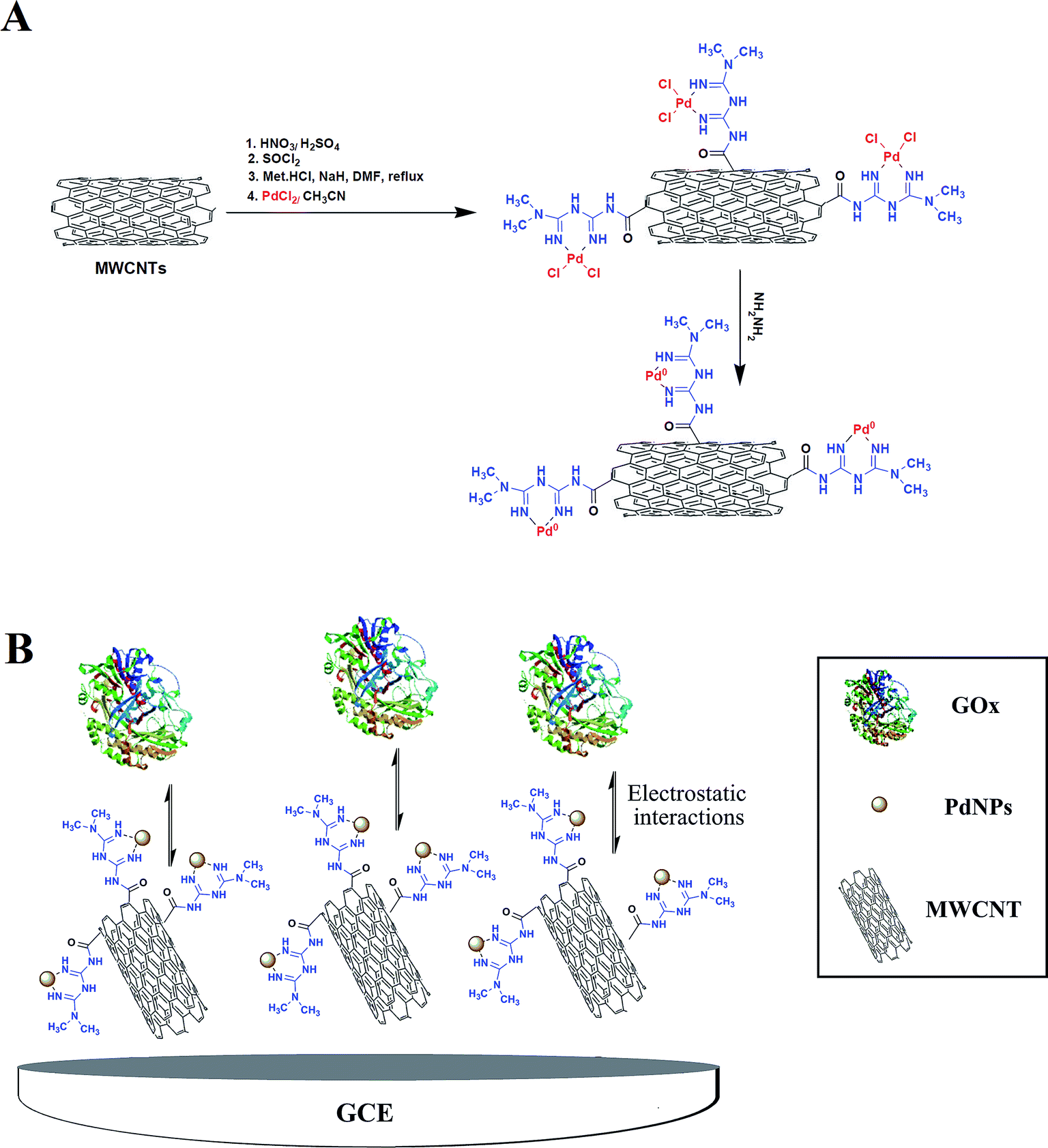
Covalently functionalized MWCNT with metformin (Met/fMWCNT) was further functionalized with PdNPs, producing a novel nanocomposite material: Pd@Met/fMWCNT. Scheme 1A shows the preparation of Pd@Met/fMWCNT nanocomposite. In brief, an aqueous solution of PdCl2 (10 mL, 0.6 mmol) was added to a dispersion of Met/fMWCNT (1 g) in acetonitrile (30 mL) and sonicated for 10 minutes. The mixture was stirred for 24 hours at room temperature to complete attainment of coordination (Pd2+@Met/fMWCNT). The obtained Pd2+@Met/fMWCNT material was centrifuged, washed with acetonitrile and deionized water, and dried in a vacuum at 40 °C for 12 hours. For preparation of Pd@Met/fMWCNT nanocomposite, in a typical experiment 100 μL of hydrazine hydrate (80%) was added to 30 mg colloidal solution of Pd2+@Met/fMWCNT in 60 mL of water, followed by adjustment of pH to 10 via addition of ammonium hydroxide (25%) with stirring at 95 °C for 2 hours. The final Pd@Met/fMWCNT nanocomposite was washed with water and dried in a vacuum at 50 °C.
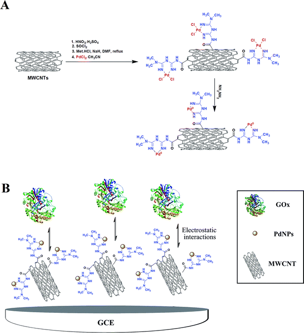 |
| | Scheme 1 (A) Synthetic pathway of Pd@Met/fMWCNT nanocomposite. (B) The electrode construction pathway. | |
2.6 Preparation of Pd@Met/fMWCNT nanocomposite modified electrode
The glassy carbon electrode was prepared by a simple casting method. Prior to use, the GCE was polished with 1.0 and 0.3 μm alumina powder to obtain a mirror-like surface, and rinsed with doubly distilled water, followed by sonication in ethanol solution and doubly distilled water successively. Then 15 cycle scans were carried out in the potential range of −2.0 to +2.0 V vs. reference electrode in a solution of 1 M H2SO4. Finally, the electrode was thoroughly washed with deionized water and dried for 3 minutes at 40 °C in an oven. The nanocomposite (0.5 mg) was kept on ultrasonic dispersing for 3 minutes in methanol (0.5 mL, 0.5%) solution. The obtained suspension (6 μL) was then cast onto the GCE and dried in air at room temperature. The modified electrode can be expressed as Pd@Met/fMWCNT/GCE. Then, 6 μL of 2.5 mg mL−1 GOx in 0.1 M PBS of pH 5 was dropped on the Pd@Met/fMWCNT/GCE and allowed to dry in a refrigerator at 4 °C for 5 hours. Finally, the GOx-immobilized electrode was rinsed throughout with 0.1 M pH 7.0 PBS to wash away the loosely adsorbed GOx molecules (Scheme 1B). The obtained electrode was labeled as GOx–Pd@Met/fMWCNT/GCE. To compare with GOx–Pd@Met/fMWCNT/GCE, GOx–GCE, GOx–Met/fMWCNT/GCE and GOx–fMWCNT/GCE were also fabricated according to the same casting method.
3. Results and discussion
3.1 Structural and morphological studies
The morphological characteristics of the Met/fMWCNT and Pd@Met/fMWCNT nanocomposite were analyzed by TEM. The TEM image of Met/fMWCNT in Fig. 1A shows that the average diameter of the Met/fMWCNT was 15–20 nm. Fig. 1B is a typical TEM image of Pd@Met/fMWCNT nanocomposite, and shows that covering the MWCNTs with a continuous PdNPs adlayer extends the overall length of MWCNTs. It can be seen that although PdNPs are distributed on MWCNTs, they do not aggregate with each other because the imine groups of metformin effectively isolate adjacent PdNPs. The average PdNPs size is 5–10 nm.
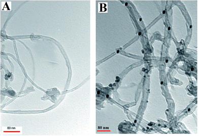 |
| | Fig. 1 TEM images of (a) Met/fMWCNT and (b) Pd@Met/fMWCNT nanocomposite. | |
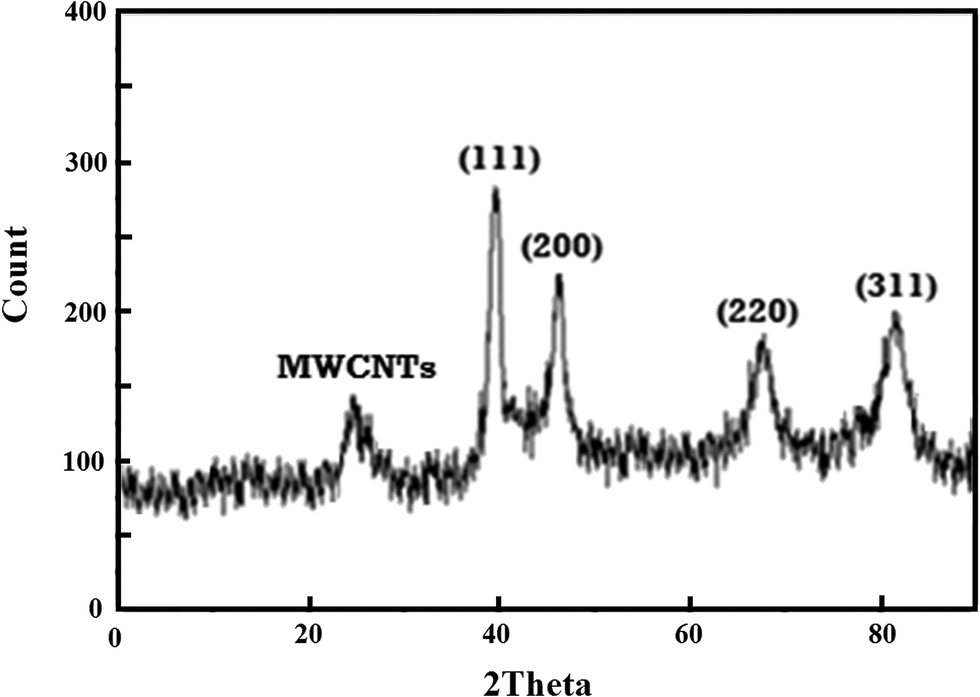
In Fig. 2, the XRD pattern of Pd@Met/fMWCNT nanocomposite shows that a wide diffraction peak at 2θ = 25°, which can be indexed to disorderedly stacked hexagonal graphite structure. There are several strong reflection peaks at 2θ values of 40°, 47°, 68° and 83°; these peaks can be assigned to (111), (200), (220) and (311) crystal planes of Pd0. Thus the XRD results indicate efficient immobilization of fcc structured PdNPs on Met/fMWCNT nanocomposite.
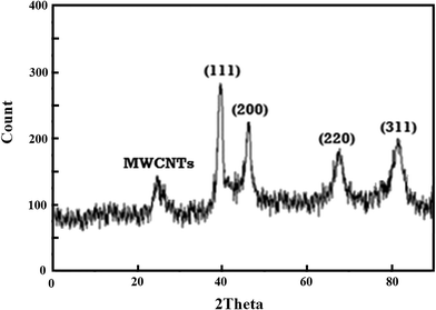 |
| | Fig. 2 XRD patterns of Pd@Met/fMWCNT nanocomposite. | |
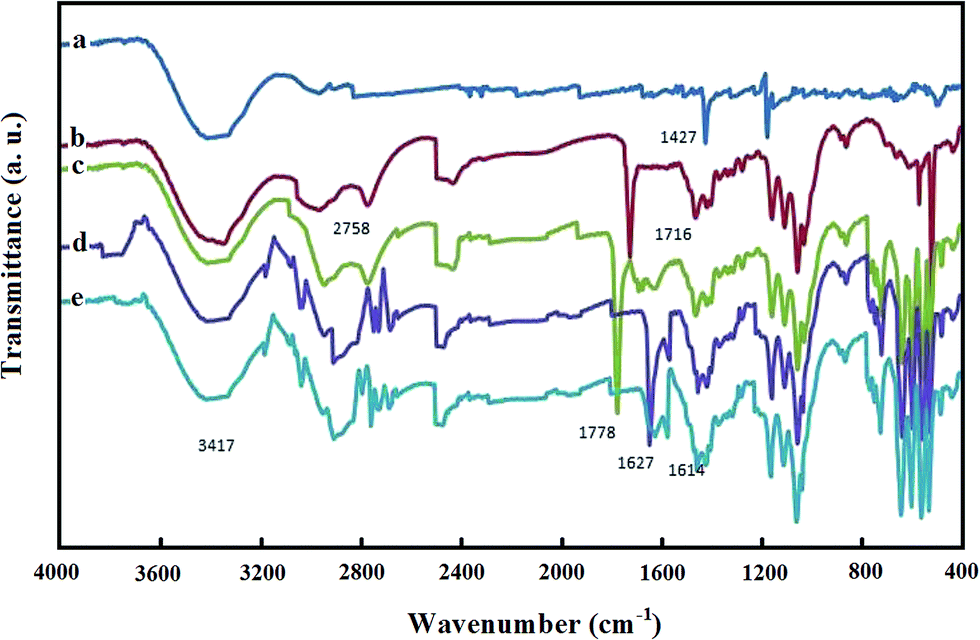
FT-IR spectra were recorded to characterize the structure of Pd@Met/fMWCNT nanocomposite and illuminate the existing state of the adsorbed GOx. Fig. 3 shows the FT-IR spectra of (a) p-MWCNTs, (b) MWCNT–COOH, (c) MWCNT–COCl, (d) Met/fMWCNT, and (e) Pd@Met/fMWCNT samples. Fig. 3, curve a, is the FT-IR spectra of p-MWCNTs. The band at 1728 cm−1, as seen in curve b, corresponds to the carbonyl stretch of the carboxylic acid group. Conversion of the carboxylic acid groups (MWCNT–COOH) into the acyl chloride intermediate (MWCNT–COCl) by treatment with thionyl chloride was confirmed by the appearance of a peak near 1778 cm−1 stretching in curve c. Curve d shows the spectrum of Met/fMWCNT, and the absorption band at 1658 cm−1 was attributed to the carbonyl stretching of the amide groups (–CONH–). The band in the spectral region of 1671 cm−1 can be assigned to the imine (C![[double bond, length as m-dash]](https://www.rsc.org/images/entities/char_e001.gif) NH) bond of the attached metformin. These results indicate that the metformin bonded to the surface of MWCNTs through an amidation reaction. It is presumed that the signals appearing at 1671 and 1658 cm−1 in curve d for the metal–ligand coordination shift to lower frequencies (1671–1656 cm−1). This shift can be observed by comparing curve e. These peaks at curves d and e indicate successful attachment of metformin organic ligands and subsequent coordination of PdNPs within the hybrid material.
NH) bond of the attached metformin. These results indicate that the metformin bonded to the surface of MWCNTs through an amidation reaction. It is presumed that the signals appearing at 1671 and 1658 cm−1 in curve d for the metal–ligand coordination shift to lower frequencies (1671–1656 cm−1). This shift can be observed by comparing curve e. These peaks at curves d and e indicate successful attachment of metformin organic ligands and subsequent coordination of PdNPs within the hybrid material.
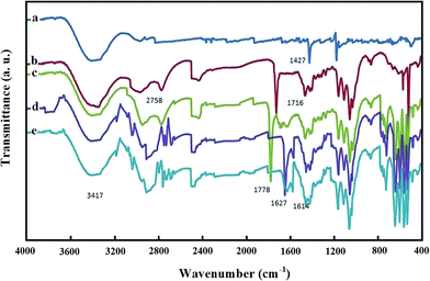 |
| | Fig. 3 FT-IR spectra of (a) MWCNT, (b) MWCNT–COOH, (c) MWCNT–COCl, (d) Met/fMWCNT, and (e) Pd@Met/fMWCNT. | |
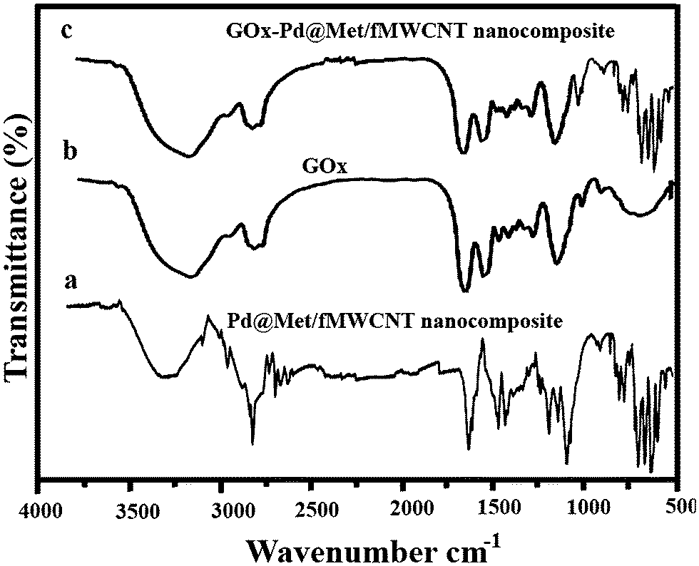
Interactions between Pd@Met/fMWCNT nanocomposite and GOx are evaluated in Fig. 4. A comparison of pure Pd@Met/fMWCNT nanocomposite (curve a) and native GOx (curve b) confirms the incorporation of GOx into the Pd@Met/fMWCNT nanocomposite (curve c). For native GOx (curve b), the intense absorption at 3409 cm−1 is assigned to the N–H stretching, and the characteristic peaks were observed at 1624 and 1537 cm−1, which are attributed to amide I (the CO stretching vibrations of the peptide bond groups) and II (the N–H in-plane bending and C–N stretching modes of the polypeptide chains) bands.33 The spectrum of GOx–Pd@Met/fMWCNT (curve c) also shows two characteristic adsorption bands at 1630 and 1542 cm−1, suggesting that GOx has been successfully immobilized on the Pd@Met/fMWCNT nanocomposite. The slight shift of the adsorption bands corresponding to amide I and II may come from intermolecular interaction between enzyme and Pd@Met/fMWCNT nanocomposite, which can effectively prevent the leaching of GOx from the Pd@Met/fMWCNT nanocomposite. These results prove that the fabricated Pd@Met/fMWCNT nanocomposite provides a favorable microenvironment for the enzyme to maintain good bioactivity.
 |
| | Fig. 4 FT-IR spectra of (a) native GOx, (b) pure Pd@Met/fMWCNT nanocomposite and (c) GOx–Pd@Met/fMWCNT. | |
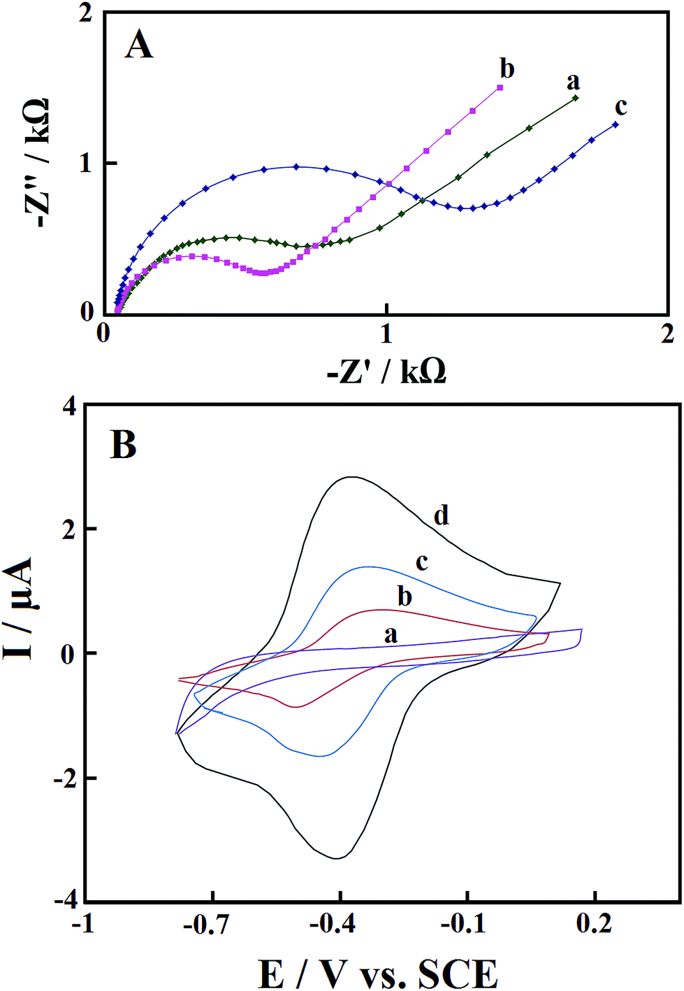
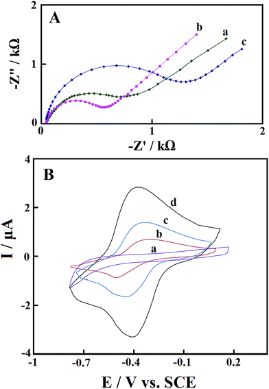
3.2 Electrochemical impedance spectroscopy
EIS is a very useful technique for determination of the electrochemical frequency behavior of surface modified electrodes. It gives information on the charge transport behavior of the electrode material at the electrode/electrolyte interface. A Nyquist plot is the most extensively used plot for EIS analysis. It is the plot of real component (Z′) of the impedance with the imaginary component (Z′′). Fig. 5A shows the Nyquist plots of the bare GCE (curve a), Pd@Met/fMWCNT/GCE (curve b), and GOx–Pd@Met/fMWCNT/GCE (curve c), recorded at open circuit potential in a 3.0 mM 1:1 K3[Fe(CN)6]/K4[Fe(CN)6] solution. The area at higher frequency represents the electrolyte properties, and the region in the middle frequency is related to the electrode/electrolyte interface processes. The intercept of the curve with the real axis is the solution resistance (Rs), and the depressed semicircle at the higher frequency region represents the charge-transfer resistance (Rct) of the electrode materials. From the Nyquist plot, charge-transfer resistances of 0.78 and 0.50 kΩ have been determined for bare GCE and Pd@Met/fMWCNT/GCE, respectively. The lowest Rct value of the Pd@Met/fMWCNT/GCE indicates that the Pd@Met/fMWCNT nanocomposite can decrease the charge-transfer resistance of the GCE. When GOx was immobilized on the Pd@Met/fMWCNT nanocomposite, the Rct increased to 1.4 kΩ. These results indicate that GOx was steadily immobilized on the Pd@Met/fMWCNT nanocomposite, causing inhibition of the electron transfer of the redox couple.33
 |
| | Fig. 5 (A) Nyquist plots of (a) bare GCE, (b) Pd@Met/fMWCNT/GCE, and (c) GOx–Pd@Met/fMWCNT/GCE in 1.0 mM K3Fe(CN)6/K4Fe(CN)6 with 0.10 M KCl as the supporting electrolyte. AC amplitude: 5 mV; frequency range: 0.1–105 Hz. (B) CVs of (a) GOx–GCE, (b) GOx–fMWCNT/GCE, (c) GOx–Met/fMWCNT/GCE, and (d) GOx–Pd@Met/fMWCNT/GCE in N2-saturated 0.1 M, pH 7.0 PBS at scan rate of 0.1 V s−1. | |
3.3 Direct electrochemistry of GOx
Fig. 5B shows cyclic voltammograms (CVs) of GOx–GCE (a), GOx–fMWCNT/GCE (b), GOx–Met/fMWCNT/GCE (c) and GOx–Pd@Met/fMWCNT/GCE (d) in N2-saturated 0.1 M, pH 7.0 PBS at scan rate of 0.1 V s−1. No redox peaks were observed from a CV of GOx–GCE, which revealed that direct electrochemistry of GOx was not achieved at conventional solid GCE. The CVs of both GOx–fMWCNT/GCE and GOx–Met/fMWCNT/GCE showed a pair of redox peaks, and the formal redox potentials (half of sum of anodic and cathodic peak potential, E0′) are −0.4 V and −0.39 V (vs. SCE), respectively. The CVs of GOx–Pd@Met/fMWCNT/GCE show a well-defined and nearly symmetric redox couple at E0′ of −0.38 V, with very low ΔEp of 30 mV. This redox couple can be assigned to the oxidation and reduction of the FAD center of GOx at the GOx–Pd@Met/fMWCNT modified GCE.34 Furthermore, the ratio of the anodic peak current (Ipa) and cathodic peak current (Ipc) is approximated to 1, revealing a fast electron transfer process between the redox center of GOx and the electrode surface.35 In addition, Ipc and Ipa of GOx–Pd@Met/fMWCNT modified GCE were 4- and 2.1-fold higher than that of GOx–fMWCNT/GCE and GOx–Met/fMWCNT/GCE, respectively. The enhanced redox peak currents and very low ΔEp value indicate that GOx is highly immobilized onto the surface of electrode owing to its strong interaction with Pd@Met/fMWCNT nanocomposite. Plausible reasons for this fascinating behavior are the large surface area, effective interaction and high conductivity of Pd@Met/fMWCNT nanocomposite offered by the synergistic effect and operative connection of two highly conducting materials, PdNPs and fMWCNT.
According to Laviron's equation,36 integrating the cathodic and anodic peaks of the CVs, the surface coverage of GOx on the electrode surface of GOx–Pd@Met/fMWCNT/GCE was estimated to be 4.17 × 10⁻¹⁰ mol cm−2. This value is much larger than the theoretical value (2.86 × 10⁻¹² mol cm−2) for the monolayer of GOx on the bare electrode surface,35 suggesting that immobilized GOx takes part in the direct electron transfer.
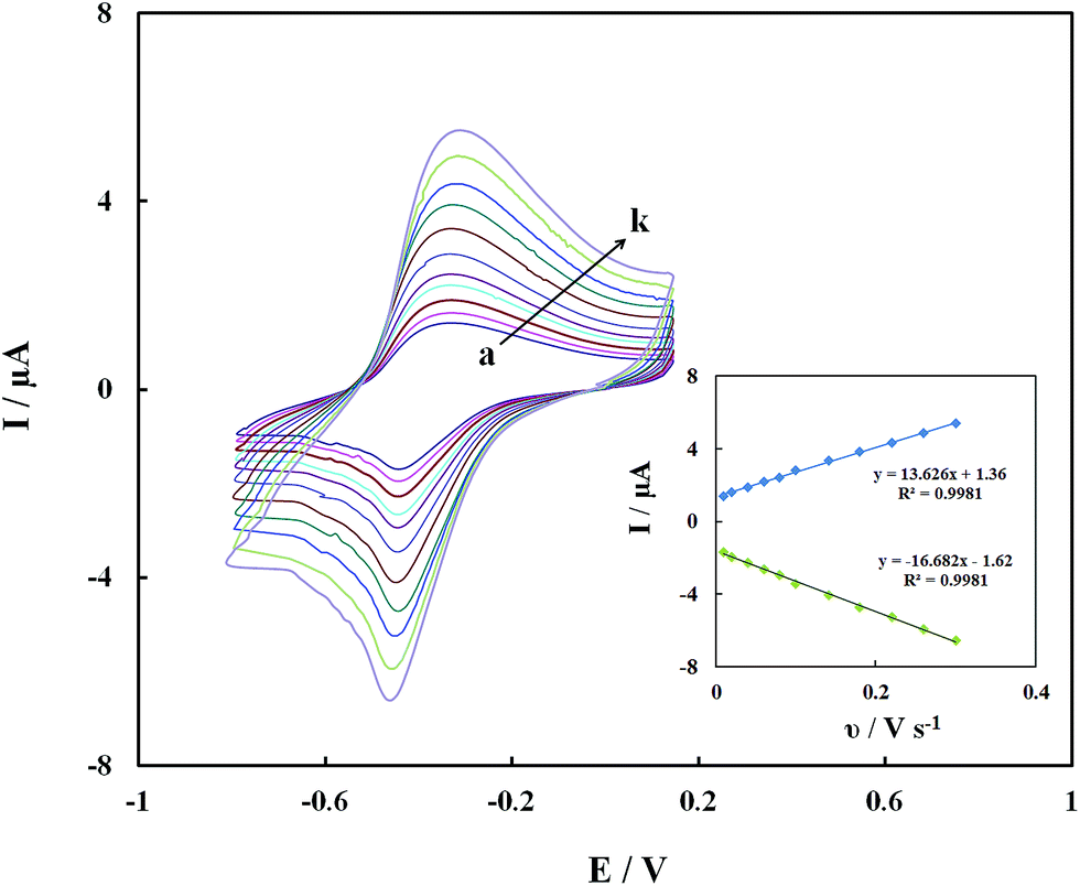
The redox currents of the GOx–Pd@Met/fMWCNT/GCE were dependent on the scan rates. Fig. 6 shows the CVs of the GOx–Pd@Met/fMWCNT/GCE in 0.1 M PBS (pH 7.0) at various scan rates. It can be seen that the redox peak currents increase and the redox peak potentials shift simultaneously with the increase of scan rates, and the peak-to-peak separation becomes greater, indicating the more irreversible nature of the electrode process. The redox peak currents had almost the same values in the selected range of scan rates, which indicated that all the electroactive FAD center in GOx(FAD) was reduced to GOx(FADH2) on the forward scan, and the GOx(FADH2) was reoxidized to GOx(FAD) on the reverse scan. The redox peak currents increased linearly with the scan rate from 0.01 to 0.3 V s−1, as shown in the inset of Fig. 6. The relationships of the redox peak currents (Ip) with scan rate (ν) were further investigated with two well-defined straight lines, as Ipa (μA) = 1.36 + 13.626ν (V s−1) (R2 = 0.9981) and Ipc (μA) = −1.62 − 16.682ν (V s−1) (R2 = 0.9981), respectively. The experimental results prove that this redox process is a typical surface-controlled electrode process.37
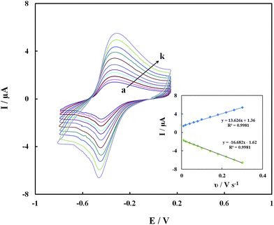 |
| | Fig. 6 CVs of GOx–Pd@Met/fMWCNT/GCE in 0.1 M PBS (pH 7.0) at different scan rates of (a) 0.01, (b) 0.02, (c) 0.04, (d) 0.06, (e) 0.08, (f) 0.10, (g) 0.14, (h) 0.18, (i) 0.22, (j) 0.26 and (k) 0.30 V s−1. Inset: plot of the peak current against the scan rate. | |
The charge-transfer rate constant (ks) of the immobilized GOx on the Pd@Met/fMWCNT/GCE can be estimated based on Laviron equation:38
| | |
logks = αlog(1 − α) + (1 − α)logα – log(RT/nFν) − (1 − α)αFΔEp/2.3RT
| (1) |
Taking an electron transfer coefficient α of 0.5, and a scan rate 0.3 mV s−1, ΔEp = 0.13 V, the rate constant calculated to be 3.24 s−1, which is larger than that of GOx/fMWCNT/GCE (1.74 s−1). This result implied that Pd@Met/fMWCNT has more effective sites on the surface for interaction with the reactive center of GOx, resulting in improved communication between active site of GOx and electrode. Also, the ks value of GOx at GOx–Pd@Met/fMWCNT/GCE is higher than that of GOx immobilized on functionalized carbon nanotubes within a dihexadecylphosphate film (1.69 s−1)39 and GOx incorporated in biomediated gold nanoparticles–carbon nanotubes composite film (2.2 s−1),40 GOx immobilized onto graphene nanosheets and carbon nanospheres mixture (2.64 s−1)41 and GOx immobilized on graphene quantum dots modified carbon ceramic electrode (1.12 s−1),42 suggesting that the immobilized GOx on the Pd@Met/fMWCNT nanocomposite achieved a relatively fast electron transfer process. This could be a result of the synergistic effect of PdNPs and fMWCNT, and is of vital importance to electron transfer between the GOx and the electrode.
3.4 Performance of the proposed glucose biosensor
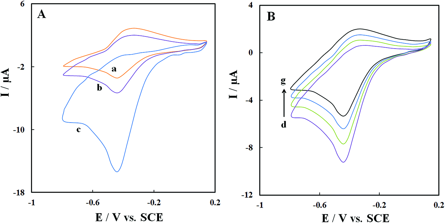
Fig. 7A shows CVs of GOx–Pd@Met/fMWCNT/GCE in (pH 7.0) N2-saturated PBS (curve a), air-saturated PBS (curve b) and O2-saturated PBS (curve c) at scan rate 0.1 V s−1. A clear increase can be observed in cathodic peak current and a simultaneous decrease in anodic peak current of GOx in the air-saturated PBS (curve b) and O2-saturated PBS (curve c), demonstrating an electrocatalytic process toward reduction of dissolved oxygen according to following equations:43| | |
GOD(FAD) + 2H+ + 2e− → GOD(FADH2)
| (2) |
| | |
GOD(FADH2) + O2 → GOD(FAD) + H2O2
| (3) |
 |
| | Fig. 7 (A) CVs of GOx–Pd@Met/fMWCNT/GCE in N2-saturated (a), air-saturated (b) and O2-saturated (c) 0.1 M, pH 7.0 PBS at 0.06 V s−1. (B) CVs of GOx–Pd@Met/fMWCNT/GCE in air-saturated 0.1 M, pH 7.0 PBS containing 0, 0.2, 0.4 and 0.6 mM glucose (from (d) to (g)) at scan rate of 0.1 V s−1. | |
Fig. 7B shows the CVs of GOx–Pd@Met/fMWCNT/GCE in the air-saturated stirring PBS (pH 7.0) containing different concentrations of glucose. Increasing the glucose concentration caused the reduction current response to decrease. In other words, as shown in eqn (4), the enzyme-catalyzed reaction decreases GOD(FAD) and curbs the electrochemical reaction:29
| | |
GOD(FAD) + glucose → GOD(FADH2) + gluconolactone
| (4) |
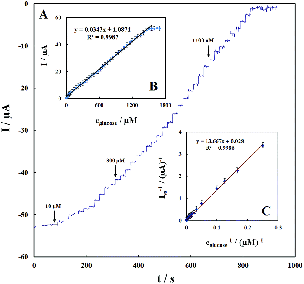
Fig. 8A shows the amperometric response of the GOx–Pd@Met/fMWCNT/GCE on successive additions of glucose to 0.1 M PBS (pH 7.0) at a detection potential of −0.47 V. Immediately after the addition of glucose, the response increases and reaches 95% of the steady-state value within ∼3 seconds, suggesting that the GOx–Pd@Met/fMWCNT/GCE responds rapidly to the change in the substrate concentration. The electrode linearly responds to glucose at lower concentrations and attains saturation levels at higher concentrations (Fig. 8B). The response displays a good linear range from 4 to 1500 μM, with a correlation coefficient of 0.9987 and a slope of 0.0343 ± 0.2 μA μM−1. The limit of detection (S/N = 3) is estimated to be ca. 1.4 ± 0.04 μM, which is comparable with or, in most cases, broader than the reported value of 1.0 μM glucose oxidase in electropolymerized poly(o-phenylenediamine) film on Pt nanoparticles–polyvinylferrocenium,25 0.01 mM glucose biosensor based on glucose oxidase immobilized on AuPt nanoparticle–carbon nanotube–ionic liquid hybrid coated electrode,44 0.2 mM glucose oxidase incorporated into biomediated gold nanoparticles–carbon nanotubes composite film,40 100 μM graphene/polyaniline/Au nanoparticles/glucose oxidase biocomposite modified electrode,45 0.16 mM glucose oxidase immobilized on reduced graphene oxide and silver nanoparticles nanocomposite,30 and 1.7 μM glucose oxidase on three-dimensional interpenetrating, porous graphene modified electrode.35 These results indicate that the biosensor possesses high bioelectrocatalytic activity toward glucose detection. When the glucose concentration is higher than 1.5 mM, a response plateau is observed, which indicates the characteristics of the Michaelis–Menten kinetic mechanism. Based on the Lineweaver–Burk equation, the apparent Michaelis–Menten constant (KMapp) can be obtained (eqn (5)).46
| | |
(1/Iss) = (1/Imax) + (KMapp/ImaxC)
| (5) |
where
Iss is the steady-state current after the addition of the substrate,
C is the bulk concentration of the substrate, and
Imax is the maximum current measured under saturation conditions. From the Lineweaver–Burk plot (
Fig. 8C), the
KMapp value is calculated to be 0.48 mM, which is significantly smaller than 2.95 mM of GOx immobilized onto glassy carbon electrode modified with nitrophenyl diazonium salt
47 and also smaller than 0.6 mM GOx immobilized onto graphene/polyaniline/gold nanoparticles nanocomposite,
27 and 0.71 mM for GOx immobilized onto graphene quantum dots.
42 This result revealed that the Pd@Met/fMWCNT nanocomposite provides an operative microenvironment for GOx to retain its native biological activity because of effective adsorption of GOx and the electrical network formed through direct binding of PdNPs with the fMWNTs.
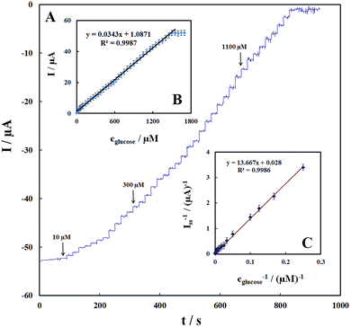 |
| | Fig. 8 (A) Amperometric response of the glucose biosensor to successive addition of different concentration of glucose into a stirring air-saturated 0.1 M PBS (pH 7.0) at the working potential of −0.47 V. (B) Plot of electrocatalytic peak current vs. concentration of glucose. (C) Plot of the reciprocal of steady-state current (Iss) versus the reciprocal of glucose concentration for the GOx–Pd@Met/fMWCNT/GCE. | |
3.5 Stability and reproducibility of the biosensor
The GOx–Pd@Met/fMWCNT/GCE was stored at 4 °C, and the stability was investigated by measuring the cyclic voltammogram periodically. The results indicated that the peak potentials and currents of biosensor were stable for ten days and then decreased gradually. Also, the cyclic voltammetric peak potentials appeared at the same position, with the peak current decreasing by 16% compared with the initial response after 1 month. The reproducibility of the proposed biosensor towards glucose detection was also studied. The R.S.D. of inter-electrode responses to 100 μM glucose at five different electrodes was 4.54% while the R.S.D. of intra-electrode responses to five-times repeated additions of 100 μM glucose was 3.1%. These results indicate that the GOx–Pd@Met/fMWCNT/GCE was efficient at retaining high enzymatic activity and preventing enzyme leakage from the Pd@Met/fMWCNT nanocomposite, which is very important for development of the proposed biosensor in a low-cost application.
3.6 Selectivity and real sample analysis
In practice, some substrates in biological systems may influence detection of glucose, so the selectivity of biosensor was evaluated by glucose measurements in the presence of a number of interfering substances such as ascorbic acid (AA), uric acid (UA), dopamine (DA) and acetaminophen (AC). The current response obtained in the mixture of glucose and the mentioned interfering species was compared with the results obtained in the pure glucose solution. As shown in Table 1, all these interferences have little influence on determination of glucose. Similarly, interfering signals from 0.5 mM L-cysteine, and 1.0 mM Ca2+, Mg2+ and 2.0 mM Cl− do not influence the performance of the biosensor. This result indicates that the proposed biosensor has high selectivity for glucose and is suitable for practical applications. The performance of the biosensor for practical application in the analysis of real samples was investigated using human serum and urine samples under optimum conditions without any sample pretreatment other than a dilution step with PBS (pH 7.0) by the standard additional method. The determined results were compared with those obtained by a spectrophotometric method in a standard clinical laboratory, and these are summarized in Table 2. As shown, the results obtained by the biosensor are in good agreement with those measured by the spectrophotometric method in the clinical laboratory.
Table 1 Effects of possible interfering agents on determination of glucose at GOx–Pd@Met/fMWCNT/GCE
| Substratesa |
Response currentb (μA) |
Current ratioc |
| The concentrations of substrates were glucose: 1.0 mM; AA: 2.0 mM; UA: 3.0 mM, DA: 2.0 mM and AC: 1.0 mM. Average of five determinations ± standard deviation. Current ratio is the current from a mixture of interfering substances and glucose (with mentioned concentrations) vs. the current from 1.0 mM glucose alone. Assay solution: 0.1 M pH 7.0 PBS. |
| Glucose |
35.5 ± 0.06 |
— |
| Glucose + AA |
35.8 ± 0.05 |
1.00 |
| Glucose + UA |
36.0 ± 0.03 |
1.01 |
| Glucose + DA |
35.4 ± 0.06 |
99.7 |
| Glucose + AC |
35.4 ± 0.04 |
99.7 |
Table 2 Results of glucose determination and the recovery test for real samples (n = 5)a
| Serum sample |
Added (mM) |
Found (mM) |
Determined by spectrophotometry |
Recovery (%) |
| A and B samples of glucose in human serum. C and D samples of glucose in human urine. |
| A |
0 |
0.64 ± 0.07 |
0.67 |
— |
| 0.3 |
0.96 ± 0.06 |
— |
102.1 |
| 0.5 |
1.13 ± 0.03 |
— |
99.12 |
| B |
0 |
0.78 ± 0.05 |
0.76 |
— |
| 0.2 |
0.97 ± 0.05 |
— |
98.97 |
| 0.6 |
1.40 ± 0.04 |
— |
101.4 |
| C |
0 |
— |
— |
— |
| 0.2 |
0.193 ± 0.05 |
0.21 |
96.5 |
| 0.4 |
0.41 ± 0.04 |
0.41 |
102.5 |
| D |
0 |
— |
— |
— |
| 0.3 |
0.306 ± 0.04 |
0.295 |
102 |
| 0.5 |
0.507 ± 0.07 |
0.51 |
101.4 |
4. Conclusions
We have reported here a successful way to deposit PdNPs on functionalized MWCNT surface using metformin with high dispersion and effective adhesion without affecting the electronic network of the tubes. Pd@Met/fMWCNT nanocomposite has been successively applied to adsorption of GOx to achieve DET of GOx, fabricating an electrochemical glucose biosensor. The favorable results are attributed mainly to the synergistic effects of PdNPs with Met/fMWCNT in immobilization of GOx, and the electrical conductivity of the nanocomposite film. Furthermore, the modified electrode possesses good selectivity, stability and reproducibility. Therefore, the proposed biosensor offers an effective method for determination of glucose in real samples and has potential applications in the study of the direct electrochemistry of redox proteins/enzymes and the development of third-generation biosensors.
Acknowledgements
We would like to thank the Hakim Sabzevari University for its financial support.
References
- V. K. Gupta, M. R. Ganjali, P. Norouzi, H. Khani, A. Nayak and S. Agarwal, Crit. Rev. Anal. Chem., 2011, 41, 282–313 CrossRef CAS.
- R. Jain, V. K. Gupta, N. Jadon and K. Radhapyari, Anal. Biochem., 2010, 407, 79–88 CrossRef CAS PubMed.
- V. K. Gupta, A. K. Singh, S. Mehtab and B. Gupta, Anal. Chim. Acta, 2006, 566, 5–10 CrossRef CAS.
- V. K. Gupta, A. K. Singh, M. Al Khayat and B. Gupta, Anal. Chim. Acta, 2007, 590, 81–90 CrossRef CAS PubMed.
- V. K. Gupta, R. Prasad, P. Kumar and R. Mangla, Anal. Chim. Acta, 2000, 420, 19–27 CrossRef CAS.
- R. N. Goyal, V. K. Gupta and S. Chatterjee, Electrochim. Acta, 2008, 53, 5354–5360 CrossRef CAS.
- S. K. Arya, T. S. Pui, C. C. Wong, S. Kumar and A. R. A. Rahman, Langmuir, 2013, 29, 6770–6777 CrossRef CAS PubMed.
- V. K. Gupta, A. K. Jain and G. Maheshwari, Talanta, 2007, 72, 1469–1473 CrossRef CAS PubMed.
- V. K. Gupta, A. K. Jain, S. Agarwal and G. Maheshwari, Talanta, 2007, 71, 1964–1968 CrossRef CAS PubMed.
- S. Alwarappan, G. Liu and C.-Z. Li, Nanomedicine, 2010, 6, 52–57 CrossRef CAS PubMed.
- L. Qu and L. Dai, J. Am. Chem. Soc., 2005, 127, 10806–10807 CrossRef CAS PubMed.
- S. Alwarappan, S. Prabhulkar, A. Durygin and C.-Z. Li, J. Nanosci. Nanotechnol., 2009, 9, 2991–2996 CrossRef CAS PubMed.
- R. N. Goyal, V. K. Gupta and S. Chatterjee, Sens. Actuators, B, 2010, 149, 252–258 CrossRef CAS.
- R. N. Goyal, V. K. Gupta and S. Chatterjee, Talanta, 2008, 76, 662–668 CrossRef CAS PubMed.
- S. Dhibar and C. K. Das, Ind. Eng. Chem. Res., 2014, 53, 3495–3508 CrossRef CAS.
- M. Baghayeri, E. N. Zare and M. Namadchian, Sens. Actuators, B, 2013, 188, 227–234 CrossRef CAS.
- A. Senthil Kumar, P. Gayathri, P. Barathi and R. Vijayaraghavan, J. Phys. Chem. C, 2012, 116, 23692–23703 CAS.
- P. C. Ma, B. Z. Tang and J.-K. Kim, Carbon, 2008, 46, 1497–1505 CrossRef CAS.
- S. Zheng, J. Hu, L. Zhong, L. Wan and W. Song, J. Phys. Chem. C, 2007, 111, 11174–11179 CAS.
- H. Ahmar, S. Keshipour, H. Hosseini, A. R. Fakhari, A. Shaabani and A. Bagheri, J. Electroanal. Chem., 2013, 690, 96–103 CrossRef CAS.
- V. Georgakilas, D. Gournis, V. Tzitzios, L. Pasquato, D. M. Guldi and M. Prato, J. Mater. Chem., 2007, 17, 2679–2694 RSC.
- Z.-P. Sun, X.-G. Zhang, Y.-Y. Liang and H.-L. Li, Electrochem. Commun., 2009, 11, 557–561 CrossRef CAS.
- R. Yu, L. Chen, Q. Liu, J. Lin, K. Tan, S. C. Ng, H. S. O. Chan, G.-Q. Xu and T. S. Andy Hor, Chem. Mater., 1998, 4756, 718–722 CrossRef.
- R. Zanella, E. V. Basiuk, P. Santiago, V. A. Basiuk, E. Mireles, I. Puente-Lee and J. M. Saniger, J. Phys. Chem. B, 2005, 109, 16290–16295 CrossRef CAS PubMed.
- E. Turkmen, S. Z. Bas, H. Gulce and S. Yildiz, Electrochim. Acta, 2014, 123, 93–102 CrossRef CAS.
- X. Zeng, X. Li, L. Xing, X. Liu, S. Luo, W. Wei, B. Kong and Y. Li, Biosens. Bioelectron., 2009, 24, 2898–2903 CrossRef CAS PubMed.
- Q. Xu, S. Gu, L. Jin, Y. Zhou and Z. Yang, Sens. Actuators, B, 2014, 190, 562–569 CrossRef CAS.
- M. A. Kamyabi, N. Hajari, A. P. F. Turner and A. Tiwari, Talanta, 2013, 116, 801–808 CrossRef PubMed.
- T. Homma, D. Sumita, M. Kondo, T. Kuwahara and M. Shimomura, J. Electroanal. Chem., 2014, 712, 119–123 CrossRef CAS.
- S. Palanisamy, C. Karuppiah and S.-M. Chen, Colloids Surf., B, 2014, 114, 164–169 CrossRef CAS PubMed.
- Y. Yu, Z. Chen, S. He, B. Zhang, X. Li and M. Yao, Biosens. Bioelectron., 2014, 52, 147–152 CrossRef CAS PubMed.
- C. W. Hills, N. H. Mack and R. G. Nuzzo, J. Phys. Chem. B, 2003, 107, 2626–2636 CrossRef CAS.
- Z. Yang, X. Huang, R. Zhang, J. Li, Q. Xu and X. Hu, Electrochim. Acta, 2012, 70, 325–330 CrossRef CAS.
- V. Mani, B. Devadas and S.-M. Chen, Biosens. Bioelectron., 2013, 41, 309–315 CrossRef CAS PubMed.
- M. Cui, B. Xu, C. Hu, H. B. Shao and L. Qu, Electrochim. Acta, 2013, 98, 48–53 CrossRef CAS.
- J.-Y. Sun, K.-J. Huang, S.-F. Zhao, Y. Fan and Z.-W. Wu, Bioelectrochemistry, 2011, 82, 125–130 CrossRef CAS PubMed.
- K.-J. Huang, J.-Y. Sun, D.-J. Niu, W.-Z. Xie and W. Wang, Colloids Surf., B, 2010, 78, 69–74 CrossRef CAS PubMed.
- E. Laviron, J. Electroanal. Chem., 1979, 101, 19–28 CrossRef CAS.
- B. C. Janegitz, R. Pauliukaite, M. E. Ghica, C. M. A. Brett and O. Fatibello-Filho, Sens. Actuators, B, 2011, 158, 411–417 CrossRef CAS.
- H. Zhang, Z. Meng, Q. Wang and J. Zheng, Sens. Actuators, B, 2011, 158, 23–27 CrossRef CAS.
- H. Yin, Y. Zhou, X. Meng, K. Shang and S. Ai, Biosens. Bioelectron., 2011, 30, 112–117 CrossRef CAS PubMed.
- H. Razmi and R. Mohammad-rezaei, Biosens. Bioelectron., 2013, 41, 498–504 CrossRef CAS PubMed.
- R. Cui, Z. Han, J. Pan, E. S. Abdel-Halim and J.-J. Zhu, Electrochim. Acta, 2011, 58, 179–183 CrossRef CAS.
- Y. Zhang, G. Guo, F. Zhao, Z. Mo, F. Xiao and B. Zeng, Electroanalysis, 2010, 22, 223–228 CrossRef CAS.
- F.-Y. Kong, S.-X. Gu, W.-W. Li, T.-T. Chen, Q. Xu and W. Wang, Biosens. Bioelectron., 2014, 56, 77–82 CrossRef CAS PubMed.
- M. Baghayeri, E. N. Zare and M. M. Lakouraj, Biosens. Bioelectron., 2014, 55, 259–265 CrossRef CAS PubMed.
- Z. Nasri and E. Shams, Electrochim. Acta, 2013, 112, 640–647 CrossRef CAS.
|
| This journal is © The Royal Society of Chemistry 2014 |
Click here to see how this site uses Cookies. View our privacy policy here.