Natural, biodegradable and flexible egg shell membranes as separators for lithium-ion batteries

M. Raja and A. Manuel Stephan*
Electrochemical Power Sources Division, CSIR – Central Electrochemical Research Institute, Karaikudi 630 006, India. E-mail: arulmanuel@gmail.com; amstephan@cecri.res.in

Received 18th August 2014 , Accepted 17th October 2014

First published on 17th October 2014


Abstract

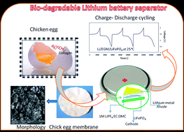
Flexible egg shell membranes (ESM) were obtained from chicken eggs after treatment with hydrochloric acid. The ESMs were subjected to scanning electron microscopy (SEM) and thermogravimetric (TG) and wettability analyses. The morphological studies revealed that the membranes possessed uniform porosity and they were of micron size. The ESM was also found to be thermally stable above 230 °C. The electrochemical properties, such as ionic conductivity, lithium transport number (Lit+) and compatibility of the membrane upon activation in 1 M LiPF6 in EC[thin space (1/6-em)]:[thin space (1/6-em)]DMC (1[thin space (1/6-em)]:[thin space (1/6-em)]1 v/v), were analyzed. Finally, a 2032-type coin cell composed of Li/ESM/LiFePO4 was assembled and its cycling profile was also analyzed at different C-rates.

Introduction

The demand for energy storage devices with high energy and power density to reduce CO2 emissions and dependence on definite resources on fossil fuels has prompted researchers to find alternative energy resources.1,2 The state-of-art lithium-ion batteries are composed of a carbonaceous anode and lithium transition metal oxide cathode, which are separated by a polyolefin separator soaked in a non-aqueous liquid electrolyte (1 M LiPF6 in EC[thin space (1/6-em)]:[thin space (1/6-em)]DEC 1[thin space (1/6-em)]:[thin space (1/6-em)]1 v/v).3 However, the safety aspect of the present lithium-ion batteries is a disturbing challenge for the users.4 The separator is an important component that prevents physical contact between the cathode and anode (precludes short-circuiting) while rapidly permitting the Li+-ions for cycling. The membrane properties, such as porosity, tortuosity, shrinkage, wettability and ionic conductivity, influence the cycling performance of the batteries. Although polyolefin membranes are widely used as separators in the commercially available lithium-ion batteries, they have several disadvantages, such as low porosity (about 40%), poor wettability and unidirectional mechanical integrity.5 Above all, it is thermally stable only up to 135 °C. Therefore, membranes with enhanced thermal stability and good wettability in organic liquid electrolytes are highly desirable to guarantee safe and reliable lithium-ion battery systems.6 Numerous reports are available on the preparation and characterization of porous membranes with high porosity and mechanical integrity for lithium-ion batteries.7,8 Phase inversion method has been widely employed for the preparation of porous membranes; however, these membranes suffer from poor rate-capability.9,10 Electrospun nanofibre-based nonwoven membranes have become very attractive in the recent years.11,12 However, the lower mechanical integrity of the highly porous membrane hinders it from practical applications.13 Intensive and numerous attempts have been made to employ ceramic membranes for lithium-ion batteries.14–17

In recent years, bio-sourced materials have been widely used to enhance the electrochemical properties of energy storage devices. Manuel Stephan et al. employed biomass-derived carbonaceous materials from banana fibers for lithium-ion batteries.18 Similarly, the performance of a supercapacitor was also studied.19 Nanoscale microfibrillated cellulose (NMFC) was introduced into a light-cured polymeric matrix as a quasi-solid electrolyte for the next generation of bio-based dye-sensitized solar cells by Annalisa and co-workers.20 According to the authors, the NMFC added polymeric membrane promoted sunlight efficiencies as high as 8.25%, and also had long-term stability and excellent durability. Dyatkin et al.21 have successfully demonstrated the performance of a green supercapacitor, composed of environmentally-friendly materials with porous acetate cellulose ester membranes, which exhibited high gravimetric capacitances with low resistance values.

Very recently, egg shell membranes (ESM) have been widely employed as a template for the synthesis of ZrO2,22 TiO2 (ref. 23) and Co3O4,24 and as precursors for carbonaceous materials.25 They have also been used as separators for supercapacitors in aqueous medium.26

Naturally, the avian egg shells are composed of a layered organization of calcified shell and organic collagen types I, V, and X, and glycosaminoglycan.27 Avian egg shell is one of the most abundant materials in the biosphere, which is non-toxic, environmentally benign and very cheap. Egg shells are hierarchically architectured with three layers, namely, outer shell membrane, inner shell membrane, and limiting membrane that surrounds the egg white.28 The outer shell membrane, which can be easily isolated from egg shells, can be used as a separator for energy devices.

Even though numerous reports are available on polymeric and ceramic-based membranes as separators for lithium-ion batteries, studies based on naturally available and bio-degradable porous membranes are very rare, despite that these membranes are truly interesting because of their cost effectiveness. To date, to the best of our knowledge, no attempt has been made to employ egg shell membranes as a separator for lithium-ion batteries. In the present work, the obtained ESMs were thoroughly characterized from the morphological and physico-chemical points of view.

Experimental

Preparation of membrane

Membranes were removed from the egg shells according to an earlier reported method.27,28 Briefly, eggs were gently broken and emptied via the blunt end and the egg shells were washed with water. Subsequently, the inner shell membrane and the limiting membrane were manually removed. The remaining egg shells were rinsed in 1 M HCl to dissolve CaCO3, leaving the organic outer shell membrane. After the outer shell membrane was thoroughly washed with water, it was further purified by 2-propanol to remove microorganisms from the fine pores of the membrane. The morphology of ESM was examined by scanning electron microscopy (SEM, Vega3, Tescan) under vacuum condition (10−1 Pa) after coating gold on one side of the membrane. The thermal stability of the egg shell membrane was analyzed by taking TG-traces in the ranges of 20 °C to 600 °C under an N2 atmosphere. The dimensional stability of the ESM was determined by storing both ESM and Celgard membrane at 125 °C in an oven for 1 h. The contact angle of the ESM with non-aqueous liquid electrolyte was measured by a contact angle tester (Data Physics OCA35, Germany). The ionic conductivity of the membrane, sandwiched between two stainless steel blocking electrodes (1 cm2 in area), was measured using an electrochemical impedance analyzer (IM6-Bio Analytical Systems) between the frequency ranges from 1 MHz to 50 mHz for various temperatures. To investigate the compatibility of the ceramic membrane with a lithium metal anode, a symmetric non-blocking cell (Li/ESM/Li) was assembled and the time dependence of the impedance was analyzed at 25 °C. The lithium transference number was calculated by the method proposed by Vincent and co-workers.29
 
image file: c4ra08491h-t1.tif(1)

The Li/CPE/Li cell was polarized by a dc pulse of 10 mv. Time evolution of the resulting current flow was then followed. The initial (I0) and steady state (Iss) values of current flowing through the cell during the polarization were measured. R0 and Rss represent the resistance values before and after the perturbation of the system. Impedance spectra were recorded before and after perturbation.

Electrochemical stability window was measured by sweep voltammetry in two stainless steel electrode–poly(propylene) symmetric cell. Acetylene black coated on an aluminum current collector and lithium metal were used as electrodes and activated ESM was used as the electrolyte. The potential scan range was from OCV to 5.5 V vs. Li, and the potential scan rate was 0.1 mV S−1.30 The thermal shut-down property of the membranes was measured as described by Zhang.31

A 2032-type coin cell was assembled to determine the cyclability of egg shell membrane. Investigation was carried out by galvanostatic charge/discharge cycling at ambient temperatures (current regimes from 0.1 C to 1 C) with an Arbin Instrument Testing System model BT-2000, setting the cut-off potentials from 2.50–4.00 V vs. Li/Li+. The composite cathode was prepared by blending LiFePO4 as the active material with acetylene black carbon and PVdF–HFP as binders.32 The ESM was soaked in a liquid electrolyte composed of 1.0 M LiPF6 (Aldrich, USA) solution in a 1 : 1 v/v mixture of ethylene carbonate (Fluka, Germany) and diethylcarbonate (Aldrich, USA). All the preparations were performed in an argon-filled glove box (MBraun, Germany) having a humidity content below 1 ppm). LiFePO4/C cathode material was synthesized in the form of nanostructured powder through a mild hydrothermal procedure, previously described in detail.30,32,33 The lithium metal foil (Aldrich, USA) was used as anode.

Results and discussions

Fig. 1(a and b) show the surface morphology of ESMs for two different magnifications. The SEM images revealed that the surface has a rough morphology and the average pore size is 1–5 microns. The interconnected pores are expected to entrap a huge amount of non-aqueous electrolyte upon soaking the membrane in it.
image file: c4ra08491h-f1.tif
Fig. 1 SEM images of ESM at different magnifications (a) ×1000 and (b) ×3000.

To ascertain the thermal stability of ESM, the thermogravimetric (TG) analysis was carried out between 25 and 600 °C. Generally, the weight loss of ESM takes place in three steps, as depicted in Fig. 2. The weight loss seen at around 50–100 °C is attributed to the removal of water and moisture from the membrane. Collagen degrades and glycon chains decompose between 220 and 400 °C.27


image file: c4ra08491h-f2.tif
Fig. 2 Thermogravimetric traces of ESM.

The irreversible decomposition starts at 240 °C. The degradation of membrane matrix takes place between 400 and 600 °C, which is in accordance with the earlier reports.25,27,27 The shutdown temperature for ESM and Celgard membranes was found to be 205 and 160 °C, respectively.

Fig. 3 shows the image of commercially available Celgard 2400 membrane and ESM, before and after heat treatment (storing both membranes at 125 °C for one hour). It is clear from the image that ESM is dimensionally more stable than the commercially available membrane.


image file: c4ra08491h-f3.tif
Fig. 3 Images of ESM and Celgard membranes before and after heat treatment at 125 °C. (a) Celgard, (b) ESM, (c) Celgard and (d) ESM.

The porosity percentage of the membrane was determined using eqn (2) as follows after soaking the ceramic membrane in n-butanol:

 
P (%) = [(M1/ρ1)/(M1/ρ1 + M2/ρ2)] × 100 (2)
where M1 and M2 denotes the masses of the dry ESM and n-butanol absorbed membrane, respectively, and ρ2 and ρ1 represent the densities of the ESM and n-butanol, respectively. The porosity of the membrane was found to be 60%. In the present study, n-butanol was selected because its viscosity is very close to that of non-aqueous liquid electrolytes used for lithium-ion batteries.34–36 The uptake of electrolyte solution was measured using eqn (3) as follows:
 
Uptake (%) = [(MM0)/M0] × 100 (3)

The uptake of the electrolyte was found to be 81%. Table 1 depicts the physical and electrochemical properties of both the ESM and Celgard membrane.

Table 1 The physical properties of ESM and Celgard membranes obtained under our laboratory conditions
Membrane properties ESM Celgard 2400^
Porosity 60% 41%
Electrolyte uptake 81% 60%
Li-ion transport number 0.47 0.44
Contact angle 65° 35°
Shutdown temperature 205 °C 160 °C


The tortuosity of the membrane is the ratio of mean capillary length to the thickness of the membrane, which describes the pore blockage and average pore connectivity.5 The tortuosity of the membrane was calculated by employing the formula (4); where σ0 and σ represents the ionic conductivity of the liquid electrolyte and activated egg shell membrane (after swelling in the electrolyte), respectively, and P represents the porosity of the membrane.

 
T = [(σ/σ0) × P]1/2 (4)

The tortuosity of the membrane was found to be 24.5.

According to Zhang and Arora,5 an ideal porous body with cylindrical and parallel pores represent a tortuosity factor equal to 1. The higher the value of tortuosity, the more the system is hindered. However, higher tortuosity leads to better dendrite resistance, but simultaneously it adversely increases separator resistance. In the present study, the tortuosity of the membrane was found to be 24.5.

The wettability of a separator with liquid electrolyte plays a pivotal role in the electrochemical properties of a cell. Poor wettability of the separator enhances the cell resistance, and thus significantly reduces the rate capability.5,8,37 The contact angle of Celgard and ESM were measured to be 65° and 35° 5′, respectively, as shown in Fig. 4. For ESM, the droplet of the electrolyte promptly infiltrated the membrane, and the contact angle was less than that of the Celgard membrane. The better wettability facilitates the high uptake of electrolyte. Reduction in the value of contact angle is attributed to the better capillary force of the pores into ESM and also close polarity between ESM and non-aqueous liquid electrolyte.37


image file: c4ra08491h-f4.tif
Fig. 4 Contact angle images of (a) Celgard and (b) ESM with non-aqueous liquid electrolyte of 1 M LiPF6 EC + DEC (1[thin space (1/6-em)]:[thin space (1/6-em)]1 v/v).

The stress–strain profile of ESM and Celgard membranes are depicted in Fig. 5. The tensile strength of Celgard membrane is 1.42 MPa with an elongation-at-break of 150%. However, ESM exhibited a tensile strength of 1.12 MPa, which is inferior to the value of Celgard membrane. A similar observation has been reported by Fan and Maier,38 where the authors reported the tensile studies on PEO-based electrolytes.


image file: c4ra08491h-f5.tif
Fig. 5 The tensile strength of Celgard and ESM membranes.

The ionic conductivity of ESM and Celgard membrane was measured for various temperatures by impedance spectroscopy; the Arrhenius behavior is depicted in Fig. 6.


image file: c4ra08491h-f6.tif
Fig. 6 Ionic conductivity vs. inverse of the temperature of ESM.

The ionic conductivity of Celgard membrane is slightly higher than that of ESM at lower temperatures; however, the order of ionic conductivity is same for both the membranes. The ESM membrane showed an ionic conductivity of the order of 10−4 S cm−1 at 30 °C. The ionic conductivity increases with the increase of temperature, resulting in the high value of 1 × 10⁻³ S cm−1 at 50 °C. The activation energy was calculated as 1.32 eV and 1.30 eV for ESM and Celgard membrane, respectively.

The lithium transference number, Lit+, is a key parameter that guarantees performance and rate capability of lithium batteries for applications in power tools.39 As mentioned in the experimental section, the lithium transference number was calculated using the eqn (1).16 Fig. 7(a and b) shows the chronoamperometric curve of ESM and Celgard membrane, respectively. Insets show their corresponding Nyquist plots before and after perturbation. Apparently, both curves (before and after perturbation) overlap, indicating that there is not considerable difference between the initial R0 and the final resistance Rss of the two Li interfaces, which further confirms the stability of the lithium electrode with the ESM.39 The value of Lit+ has been calculated as 0.47, which is slightly higher (0.44) than that of the commercially available membrane.40


image file: c4ra08491h-f7.tif
Fig. 7 The chronoamperommetric profile for (a) ESM (b) Celgard membrane activated in non-aqueous liquid electrolyte of 1 M LiPF6 EC + DEC (1[thin space (1/6-em)]:[thin space (1/6-em)]1 v/v). Insets: Nyquist plot of symmetric cell before and after perturbation.

The electrochemical stability window, which describes the cycling reversibility of battery systems, was evaluated for both, ESM and Celgard membranes. Fig. 8 illustrates the electrochemical stability window between 3.0 and 5.5 V at ambient temperatures. In the present study, for both the membranes, the decomposition of the electrolyte indicates an anodic break-down voltage of approximately 4.8 V vs. Li with low residual current.30 This high voltage decomposition is certainly favorable for practical applications.


image file: c4ra08491h-f8.tif
Fig. 8 Electrochemical stability window at room temperature for ESM and Celgard 2400 activated in non-aqueous liquid electrolyte of 1 M LiPF6 EC + DEC (1[thin space (1/6-em)]:[thin space (1/6-em)]1 v/v).

However, the current increases at a lower voltage, which is attributed to a sort of “passivation”; the reason for this behaviour is yet to be understood. A similar observation has been reported by Gerbaldi et al.,30 where the authors reported the electrochemical properties of UV-cured methacrylic-based gel polymer for lithium-ion batteries.

Although high ionic conductivity and appreciable transport number are desirable properties, they are not sufficient to guarantee that membranes are completely useful for practical applications. It is well known that the resistance of the cell is composed of the bulk resistance (Rb) of the electrolyte, and the interfacial resistance (Ri) reflects the interfacial properties of electrodes and electrolyte.41,42 To analyze the interfacial properties of ESM with a lithium metal anode, the impedance response of the symmetric cell composed of Li/ESM/Li was monitored as a function of time under open circuit voltage conditions. Generally, the interfacial resistances are measured from the Cole–Cole impedance plots (shown as an inset in Fig. 9), in which the large semi-circles represent a parallel combination of resistance (Rfilm) and capacitance associated with the passivation film on the Li electrode.41,42


image file: c4ra08491h-f9.tif
Fig. 9 Variation of interfacial resistance Ri vs. time for the symmetric cell Li/ESM/Li at 25 °C. Inset: the Nyquist plot at different time interval.

A small semicircle is because of the charge transfer resistance in parallel with the double layer capacitance. The intercept of the large semicircle at high frequency on the Z-axis is mostly associated with the interfacial resistance “Ri” of the system. Fig. 9 illustrates the variation of interfacial resistance as a function of time for the symmetric cell comprising Li/ESM/Li. The value of Ri sharply increases with time, which indicates the formation of the passivation layer on the surface of lithium. After 200 hours of storage, the value of Ri remains the same (less than 300 ohms), indicating that the ESM is stable towards a lithium metal anode. This is attributed to the porous nature of the membrane.43

Fig. 10(a and b) shows the typical charge–discharge behaviour of Li/ESM/LiFePO4 cell obtained at room temperature for different C-rates. The inset figure shows the cycling profile of the Celgard membrane at 0.1 C-rate for comparison. All the curves show a typical and flat voltage plateaus at 3.45–3.52 V vs. Li+ on charge and 3.38 and 3.30 V vs. Li on discharge, which are because of the biphasic Li+ extraction/insertion mechanism of LiFePO4 cathode. A small drop in voltage was observed from charge to discharge, indicating the lower cell resistance value. This lower cell resistance is attributed to the better adhesion of the separator on both the sides of the electrodes, which may significantly contribute for reducing the interfacial resistance of the cell.38 The discharge capacity as a function of cycle number for the cell Li/ESM/LiFePO4 is displayed for various C-rates viz., 0.1, 0.2, 0.5, 1 and 2 C. This cycling behaviour exhibits good capacity retention up to 100 cycles. To analyze the cycling ability, the cell was allowed to run for 60 cycles at 0.2 C-rate. We did not find any discernible changes in the cycling profile, and the fade in capacity per cycle was 0.1 mA h g−1. Although the cell exhibited low discharge capacity in the initial cycles, it delivered a stable cycling profile after the 11th cycle. The cell delivered a discharge capacity of 133 mA h g−1 in its first cycle and 116 mA h g−1 in its 10th cycle, indicating a fade in capacity of 1.7 mA h per cycle, attributable to the formation cycles. However, in the subsequent cycles, a stable cycling is achieved with 99% Coulombic efficiency, which is attributed to the improved interfacial property of the cell, which was substantiated by impedance spectroscopic analysis by Gerbaldi et al.30


image file: c4ra08491h-f10.tif
Fig. 10 (a) Cycling profile of Li/ESM/LiFePO4 cell. (b) Discharge capacity as a function of cycle number for the cell Li/ESM/LiFePO4 for different current regimes. Inset: cycling profile of Celgard membrane at 0.1 C-rate.

An abrupt decrease in capacity was observed at 1 C- and 2 C-rates. The reduction in the discharge capacity at higher current regime is a typical characteristic of the LiFePO4 material, which is attributable to its low electronic conductivity, and the limited diffusion of Li+-ion into its structure that causes electrode polarization.44,45 Further, the declining discharge capacity at higher C-rates may be because of the solid electrolyte interface (SEI) film formation with electrolyte decomposition.45 A recent study has also revealed that the increase in interfacial resistance value, which originates from the parameters related to the electrode design, such as thickness and density, can cause capacity-fading at higher rates.46 It is also obvious from the figure that the cell restores its specific capacity again at 0.1 C-rate from its 91st cycle, indicating that the structural stability of the cathode materials is retained.

Conclusions

A biodegradable and flexible egg shell membrane (ESM) was prepared and successfully employed as a separator for lithium ion batteries. The ESM possesses higher porosity and exhibited better wettability than the commercial membrane. The ESM was thermally stable up to 240 °C and had better compatibility with the lithium metal anode. Although the cell comprising ESM as separator delivered a discharge capacity of 60 mA h g−1 at 1 C-rate with a stable cycling, concerns about the inferior mechanical property in terms of its lower tensile strength and also its dimension would render the large-scale production of such membranes considerably difficult.

Acknowledgements

DAE-BRNS, Mumbai is gratefully acknowledged for financial support.

References

  1. J. M. Tarascon and M. Armand, Nature, 2001, 414, 359 CrossRef CAS PubMed.
  2. R. Bouchet, S. Maria, R. Meziane, A. Aboulaich, L. Lienafa, J. P. Bonnet, T. N. T. Phan, D. Bertin, D. Gigmes, D. Devaux, R. Denoyel and M. Armand, Nat. Mater., 2013, 12, 452 CrossRef CAS PubMed.
  3. A. Manuel Stephan, Eur. Polym. J., 2006, 42, 21 CrossRef CAS.
  4. P. G. Balakrishnan and T. Prem Kumar, J. Power Sources, 2006, 155, 401 CrossRef CAS.
  5. P. Arora and Z. Zhang, Chem. Rev., 2004, 104, 4419 CrossRef CAS PubMed.
  6. X. Huang, J. Solid State Electrochem., 2011, 15, 649 CrossRef CAS.
  7. J. Y. Song, Y. Y. Wang and C. C. Wan, J. Electrochem. Soc., 2000, 147, 3219 CrossRef CAS.
  8. H. Wang, H. Huang and S. L. Wunder, J. Electrochem. Soc., 2853, 200, 147 Search PubMed.
  9. Y. J. Hwang, K. S. Nahm and A. Manuel Stephan, J. Membr. Sci., 2008, 310, 349 CrossRef CAS.
  10. Y. Saito, H. Kataoka and A. Manuel Stephan, Macromolecules, 2001, 34, 6955 CrossRef CAS.
  11. Y. E. Miao, G. N. Zhu, H. Hou, Y. Y. Xia and T. Liu, J. Power Sources, 2013, 226, 82 CrossRef CAS.
  12. Y. S. Lee, Y. B. Jeong and D. W. Kim, J. Power Sources, 2010, 195, 6197 CrossRef CAS.
  13. N. Angulakshmi and A. Manuel Stephan, Electrochim. Acta, 2014, 127, 167 CrossRef CAS.
  14. J. Nunes-Pereira, A. C. Lopes, C. M. Costa, R. Leones, M. M. Silva and S. Lanceros-Mendez, Electroanalysis, 2012, 24, 2147 CrossRef CAS.
  15. J. Nunes-Pereira, A. C. Lopes, C. M. Costa, L. C. Rodrigues, M. M. Silva and S. Lanceros-Mendez, J. Electroanal. Chem., 2013, 689, 223 CrossRef CAS.
  16. M. Raja, T. P. Kumar, G. Sanjeev, L. Zolin, C. Gerbaldi and A. Manuel Stephan, Ionics, 2014, 20, 943–948 CrossRef CAS.
  17. M. Raja, N. Angulakshmi, S. Thomas, T. Prem Kumar and A. Manuel Stephan, J. Membr. Sci., 2014, 471, 103 CrossRef CAS.
  18. A. Manuel Stephan, T. Perm Kumar, R. Ramesh, S. Thomas, S. K. Jeong and K. S. Nahm, Mater. Sci. Eng., A, 2006, 430, 132 CrossRef.
  19. V. Subramanian, C. Luo, A. M. Stephan, K. S. Nahm, S. Thomas and B. Wei, J. Phys. Chem. C, 2007, 111, 7527 CAS.
  20. A. Chiappone, F. Bella, J. R. Nair, G. Meligrana, R. Bongiovanni and C. Gerbaldi, ChemElectroChem, 2014, 1, 1350 CrossRef CAS.
  21. B. Dyatkin, V. Presser, M. Heon, M. R. Lukatskaya, M. Beidaghi and Y. Gogotsi, ChemSusChem, 2013, 6, 2269 CrossRef CAS PubMed.
  22. D. Yang, L. Qi and J. Ma, J. Mater. Chem., 2003, 13, 1119 RSC.
  23. D. Yang, L. Qi and J. Ma, Adv. Mater., 2002, 14, 1543 CrossRef CAS.
  24. A. Y. Maria Christy, M. R. Jisha, A. Rhan Kim, K. S. Nahm, D. J. Yoo, E. K. Suh, T. Sri Devi Kumari, T. Prem Kumar and A. Manuel Stephan, Bull. Korean Chem. Soc., 2011, 32, 1204–1208 CrossRef.
  25. Z. Li, L. Zhang and D. Mithin, Adv. Energy Mater., 2012, 2, 431–437 CrossRef CAS.
  26. H. Yu, Q. Tang, J. Wu, Y. Lin, L. Fan, M. Huang, J. Lin, Y. Li and F. Yu, J. Power Sources, 2012, 206, 463 CrossRef CAS.
  27. F. Yi, Z. Guo, L. Zhang, J. Yu and Q. Li, Biomaterials, 2004, 25, 4591 CrossRef CAS PubMed.
  28. J. Dennis, D. Carrino, K. Yamashita and A. Caplan, Matrix Biol., 2000, 19, 683 CrossRef CAS PubMed.
  29. J. Evans, C. A. Vincent and P. G. Bruce, Polymer, 1987, 28, 2324–2328 CrossRef CAS.
  30. C. Gerbaldi, J. R. Nair, G. Meligrana, R. Bongiovanni, S. Bodoardo and N. Penazzi, J. Appl. Electrochem., 2009, 39, 2199 CrossRef CAS.
  31. S. S. Zhang, J. Power Sources, 2007, 164, 351 CrossRef CAS.
  32. S. Bodoardo, C. Gerbaldi, G. Meligrana, A. Tuel, S. Enzo and N. Penazzi, Ionics, 2009, 15, 19 CrossRef CAS.
  33. G. Meligrana, C. Gerbaldi, A. Tuel, S. Bodoardo and N. Penazzi, J. Power Sources, 2006, 160, 516 CrossRef CAS.
  34. J. A. Choi, S. H. Kim and D. W. Kim, J. Power Sources, 2010, 195, 6192 CrossRef CAS.
  35. Q. Shi, M. Yu, M. W. Zhou, Y. Yan and C. Wan, J. Power Sources, 2002, 103, 286 CrossRef CAS.
  36. J. Xi, X. Qiu, J. Li, X. Tang, W. Zhu and L. Chen, J. Power Sources, 2006, 157, 501 CrossRef CAS.
  37. J. Chen, S. Wang, L. Ding, Y. Jiang and H. Wang, J. Membr. Sci., 2014, 461, 22 CrossRef CAS.
  38. L. Z. Fan and J. Maier, Electrochem. Commun., 2006, 8, 1753 CrossRef CAS.
  39. A. Fernicola, F. Croce, B. Scrosati, T. Watanabe and H. Ohno, J. Power Sources, 2007, 174, 342 CrossRef CAS.
  40. Y. Zhu, S. Xiao, Y. Shi, Y. Yang and Y. Wu, J. Mater. Chem. A, 2013, 1, 7790 CAS.
  41. Z. Jiang, B. Carroll and K. M. Abraham, Electrochim. Acta, 1997, 42, 2667 CrossRef CAS.
  42. A. Manuel Stephan, K. S. Nahm, T. Prem Kumar, M. Anbu Kulandainathan, G. Ravi and J. Wilson, J. Power Sources, 2006, 159, 1316 CrossRef.
  43. G. B. Appetecchi, F. Croce and B. Scrosati, Electrochim. Acta, 1995, 40, 991 CrossRef CAS.
  44. S. Brutti, J. Hassoun, B. Scrosati, C. Y. Lin, H. Wu and H. W. Hsieh, J. Power Sources, 2012, 217, 72 CrossRef CAS.
  45. J. H. Kim, S. C. Woo, M.-S. Park, K. J. Kim, T. Yim, J. S. Kim and Y. J. Kim, J. Power Sources, 2013, 229, 190 CrossRef CAS.
  46. N. Angulakhsmi, S. Thomas, J. R. Nair, R. Bongiovanni, C. Gerbaldi and A. Manuel Stephan, J. Power Sources, 2013, 228, 294–299 CrossRef CAS.

This journal is © The Royal Society of Chemistry 2014