Maowen Xu†
*ab,
Yubin Niu†ab,
Chuanjun Chenab,
Jie Songc,
Shujuan Baoab and
Chang Ming Li*ab
aInstitute for Clean Energy & Advanced Materials, Faculty of Materials and Energy, Southwest University, Chongqing 400715, P.R. China. E-mail: xumaowen@swu.edu.cn; ecmli@swu.edu.cn; Fax: +86-23-68254969; Tel: +86-23-68254969
bChongqing Key Laboratory for Advanced Materials and Technologies of Clean Energies, Chongqing 400715, P.R. China
cTexas Materials Institute, University of Texas at Austin, Texas 78712, USA
First published on 1st August 2014
Novel ultra-long Na0.44MnO2 submicron slabs were fabricated through the sol–gel method, followed by high-temperature calcination. The material has a thickness ranging from 100 to 250 nm and a length varying from 10 μm to 40 μm. Electrochemical characterization indicates that the material can deliver a high capacity, larger than 120 mA h g−1 with stable cycling over 100 cycles in assembled non-aqueous Na-ion cells, the good performance of which is mainly attributed to the reduced sodium ion diffusion distance.
There are still great challenges for the performance of Na-ion batteries to catch up with Li-ion technology; thus, it is essential to explore new high-capacity sodium-based energy storage materials or to improve the known sodium compounds suitable for Na-ion cells.3 The sodium manganese oxides such as NaMnO2, Na0.67MnO2, Na0.60MnO2, Na0.44MnO2 and other Na compounds (NaxMnyAz, A = transition metal) have been considered as promising cathode materials owing to their high capacity and low cost.4–9 In general, sodium manganese oxides mainly have two kinds of structure, layered, such as Na0.67MnO2, or tunnelled, e.g. Na0.44MnO2 structure, and both have large number of vacancies for the accommodation of Na ions.10 Among them Na0.44MnO2 is particularly attractive because of its unique 3D crystal structure, which greatly facilitates Na+ mobility while stabilizing sodium ions to prevent the crystal phase from transition to spinel phase.
Na0.44MnO2 materials can be synthesized via various approaches such as the solid-state route,11–17 glycine–nitrate combustion,11,14,15 hydrothermal synthesis,18,19 thermo-chemical conversion,20 polymer-pyrolysis21 and molten salt synthesis.22 Sauvage et al.13 prepared Na0.44MnO2 following the solid-state synthesis route, which showed a reversible insertion and extraction of Na ions in Na0.44MnO2 with an initial capacity of 80 mA h g−1 at a 0.1 C rate; however, only half of the initial capacity was retained after 50 cycles, displaying poor cyclability, mainly due to failure of the Na0.44MnO2 lattice caused by extensive Na ion insertion and extraction. Na0.44MnO2 nanowires obtained by different approaches such as the solid-state method,5 polymer pyrolysis process,17 a hydrothermal approach18 and a chemical route exhibit very large surface area, single crystal powders and improved capacity cyclability. However, the solid-state reaction approach as discussed above has poor dispersion and large particle size, affecting battery performance. Both Na0.44MnO2 cathode material and the sol–gel method used for the fabrication are well known but efforts with sol–gel methods are still used frequently to create different unique structured Na0.44MnO2 materials.20,22–24 In this work, we used a sol–gel method by using a different processing procedure, as well as a different chelating agent, to control the material morphology and structures for the synthesis of a slab-like Na0.44MnO2 material with good dispersity, ultra-long length and much lower thickness in the sodium ion deintercalation direction for a high capacity, over 120 mA h g−1, and stable cycling performance of over 100 cycles. It is also revealed that the diffusion distance of sodium ions is reduced in the obtained material to effectively improve the performance of a sodium ion battery.
To synthesize the unique Na0.44MnO2 samples, a stoichiometric amount of NaNO3 (with a 10% excess of sodium) and Mn(NO3)2 (50 wt% aq.) were dissolved in distilled water and stirred for 30 min to form a mixed solution. Then, the mixed solution was added dropwise into a 60 wt% citric acid solution. The resulting solution was heated to 90 °C and stirred for 4 h to obtain a clear and viscous gel. The resultant gel was dried at 120 °C for 12 h to produce the precursor. The solid precursor was then ground and heat-treated at 450 °C in air for 6 h to decompose the nitrate and eliminate the water. After cooling down to room temperature, the powdered precursor was ground again, pelletized and then calcined at 900 °C for 15 h in air to obtain the final product. The crystal structure of the obtained samples was characterized by powder X-ray diffraction (XRD, MAXima-X XRD-7000). Furthermore, the morphology and microstructure were examined by field-emission scanning electron microscopy (SEM, JSM-6700F) and transmission electron microscopy (TEM, JEM-2100). For the electrochemical test, the cathode materials were evaluated in 2032-type coin cells using a Na disk as counter electrode and 1 M NaClO4 in ethylene carbonate–diethyl carbonate (EC–DEC, 50:
50 vol%) solution as electrolyte. The cathode film was prepared by mixing the active material (80 wt%), acetylene black (10 wt%) and polyvinylidene fluoride (PVdF, 10 wt%) in N-methyl-pyrrolidinone (NMP) into an electrode slurry, and then casting the slurry on an aluminium foil collector and drying overnight in a vacuum at 120 °C. The assembly of the cells was carried out in a dry Ar-filled glove box. The galvanostatic charge–discharge tests were performed on a LAND cycler (Wuhan Kingnuo Electronic Co., China). Cyclic voltammetric measurements were carried out at scan rates of 0.25 mV s−1 and 0.1 mV s−1 using a CHI 660e electrochemical workstation (Chen Hua Instruments Co., China).
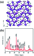
Na0.44MnO2 is isostructural to Na4Mn4Ti5O18 and crystallizes in an orthorhombic structure (space group: Pbam). Fig. 1a schematically shows that the framework of Na0.44MnO2 is built on MnO5 pyramids and MnO6 octahedra. These two kinds of polyhedra are interconnected by sharing corners to form two types of unique 1D tunnels. Thus, the prepared Na0.44MnO2 is a 3D crystal structure with interconnected unique 1D tunnels as reported in previous work.10,25 Na1 sites are located in the smaller tunnels while Na2 and Na3 are situated in the large S-shaped tunnels. These tunnels serve as diffusion paths for free transport of Na+ ions, mainly along the c-axis direction. The XRD pattern in Fig. 1b shows that the prepared Na0.44MnO2 material crystallizes well in the orthorhombic Na4Mn9O18 phase (PDF card no.: 27-0750).
![]() | ||
Fig. 1 (a) Crystal structure model of orthorhombic Na0.44MnO2 (adapted from ref. 20). (b) XRD pattern of as-prepared Na0.44MnO2 materials. |
The SEM image shows that pristine Na0.44MnO2 has a slab-like shape with scales of >20 μm (length) × ∼1 μm (width) × ∼100–250 nm (thickness) (Fig. 2a). The SEM and TEM images in Fig. 2b clearly show there is a wide range of width in Na0.44MnO2 varying from submicron to micron. The high-resolution TEM image (HRTEM) in Fig. 2c displays clear lattice fringes corresponding to the (200) plane of Na0.44MnO2 while indicating that the through-thickness orientation is along [001], which is consistent with Zhou's report.20 As discussed above, the [001] plane is perpendicular to the c axis allowing sodium ion deintercalation along the thickness direction. Fig. 2d schematically represents the morphology and sodium ion deintercalation mechanism. In the synthesis conditions described in the experimental section, sodium manganese oxide tends to a growth direction of [010], which is along the b axis direction for formation of a flat topography. During the charge–discharge cycles, sodium ion intercalation and deintercalation should go through the large S-shaped channel along the c axis direction. This in turn tells us that reduction of the thickness in the c axis direction can reduce the diffusion distance of sodium ions, which is a known significant parameter for greatly enhancing the cycling and rate performance of an ion intercalation-based battery. The diffusion coefficient (DNa+ = 2.64 × 10⁻¹⁴ cm2 s−1) was calculated from our measured impedance data based on the reported method.10
Fig. 3a shows the galvanostatic charge–discharge capacities at a 0.1 C rate, indicating excellent cyclability with a capacity retention of 100% even after 100 cycles and a coulombic efficiency of more than 90%. It should be noted that the coulombic efficiency only reaches 90% after the 10th prolonged cycle (Fig. 3a). This is possibly attributed to the slow electrode activation for the electrolyte to completely penetrate into the inner porous material surface. The different galvanostatic charge–discharge cycles (Fig. 3b) show that the specific capacity of the first charge cycle is higher than the theoretical capacity (121 mA h g−1), whereas the closely following discharge cycle has one close to the theoretical value. The extremely high capacity in the first charge cycle could be ascribed to extraction of the excess Na ions from Na1 and Na2 sites in the as-prepared material as reported.20 However, in the consecutive cycles the amount of Na ions deintercalated from the electrode should be decreased to the thermodynamic limit for a stable crystal structure.
Fig. 3b illustrates that each charge and discharge cycle has multiple steps, which is in agreement with the reported six biphasic transitions.13 For further examination of the electrochemical characteristics and cyclability of the prepared sample we conducted cyclic voltammetry (CV) studies before and after cycles. The CV curves in Fig. 3c also indicate reversibility of the six biphasic transitions during the anodic and cathodic sweeps, as observed from the galvanostatic charge–discharge cycles with their steps, and show very consistent reversibility of Na insertion and extraction before and after cycles. The distance between the discharge and charge curves is small, indicating a low electrochemical polarization.26 As can be seen in Fig. 3d, the difference ΔEafter cycles between oxidation and reduction peaks increases after the cycles. This is caused mainly by the oxidation peak being more positive than that before cycling, indicating deintercalation polarization developing with the increased number of cycles while the intercalation process does not show significant polarization.
A rationally fabricated structure of the electrodes is able to play an essential role in the improvement of electrode kinetics for better performance of an ion intercalation-based battery, which requires a nanostructure to have not only more activation sites for reversible ion inter-/deintercalation processes but also enhanced mass transport by reduced diffusion distances for Na ion intercalation during the charge–discharge cycles. Although the length and width of the slabs of the Na0.44MnO2 crystals are in the submicron to micron range, their thickness direction along the [001] c axis could facilitate easy intercalation of Na ions to achieve the theoretical capacities while accommodating the strains from Na ion insertion into the material. Fig. 3e shows that the XRD pattern scarcely has any change, in addition to the intensity of the peaks, thus evidencing that the submicron slabs can retain their intact crystal structure for long charge–discharge cycles.
In summary, ultra-long Na0.44MnO2 submicron slabs were fabricated through the sol–gel method, followed by high-temperature calcination. Results show that a Na0.44MnO2 submicron slabs-based Na-ion battery achieves its theoretical capacity value over 100 cycles, which is attributed mainly to decreased sodium ion diffusion distance and the stable crystal structure.
Footnote |
† These authors contributed equally to this work. |
This journal is © The Royal Society of Chemistry 2014 |