Theoretical study of the thermoelectric properties of SiGe nanotubes

J. Weia, H. J. Liu*a, X. J. Tana, L. Chenga, J. Zhanga, D. D. Fana, J. Shia and X. F. Tangb
aKey Laboratory of Artificial Micro- and Nano-structures of Ministry of Education and School of Physics and Technology, Wuhan University, Wuhan 430072, China. E-mail: phlhj@whu.edu.cn
bState Key Laboratory of Advanced Technology for Materials Synthesis and Processing, Wuhan University of Technology, Wuhan 430070, China

Received 19th July 2014 , Accepted 7th October 2014

First published on 7th October 2014


Abstract

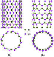
The thermoelectric properties of two typical SiGe nanotubes are investigated using a combination of density functional theory, Boltzmann transport theory, and molecular dynamics simulations. Unlike carbon nanotubes, these SiGe nanotubes tend to have gear-like geometry, and both the (6, 6) and (10, 0) tubes are semiconducting with direct band gaps. The calculated Seebeck coefficients as well as the relaxation time of these SiGe nanotubes are significantly larger than those of bulk thermoelectric materials. Together with smaller lattice thermal conductivity caused by phonon boundary and alloy scattering, these SiGe nanotubes can exhibit very good thermoelectric performance. Moreover, there are strong chirality, temperature and diameter dependences of the ZT values, which can be optimized to 4.9 at room temperature and further enhanced to 5.4 at 400 K for the armchair (6, 6) tube.


1. Introduction

Due to the increasing energy crisis and environmental pollution, there are currently growing interests in searching for advanced energy materials. Among them, the thermoelectric materials which can directly convert heat into electricity or vice versa have attracted much attention. The performance of a thermoelectric material at temperature T can be characterized by the dimensionless figure of merit:
 
ZT = S2σT/(κe + κp), (1)
which includes the Seebeck coefficient S, the electrical conductivity σ, the electronic thermal conductivity ke, and the phonon derived thermal conductivity kp. In order to compete with the traditional energy conversion methods, the ZT value of a thermoelectric material should reach at least 3. In principle, the ZT value can be improved by utilizing some strategies to increase the power factor (S2σ) and/or decrease the thermal conductivity (κe + κp). However, it is usually challenging to do so because of strong interdependence of these transport coefficients, and the ZT values of most good thermoelectric materials reported so far are found to be 1–2. Among them, silicon germanium (SiGe) alloys have long been used in thermoelectric modules for space missions to convert radio-isotope heat into electricity.1 During the past 50 years, many efforts have been made to improve the thermoelectric performance of SiGe alloys. It was found that the highest ZT value of about 1.5 can be reached at 900 °C for n-type Si0.8Ge0.2 alloy.2 For the p-type systems, however, the ZT values are relatively lower and a peak value of 0.95 can be obtained at temperature of 800–900 °C.3 In the early 1990s, Hicks and Dresselhaus4 theoretically predicated that one- and two-dimensional structures could have significantly larger ZT values than the corresponding bulk materials. The reason is that low-dimensional systems can induce enhanced phonon boundary scattering so that the thermal conductivity is reduced. Moreover, the power factor may be increased by quantum confinement and energy filtering effects. Inspired by such concept, a lot of subsequent works have been devoted to the fabrications of various low-dimensional thermoelectric materials. For example, the Bi2Te3/Sb2Te3 superlattice thin film,5 the PbSeTe/PbTe quantum dot superlattice,6 and the Si nanowires7,8 have been successfully fabricated and their enhanced thermoelectric performances are confirmed. In the case of SiGe systems, Martinez et al. reported that p-type SiGe nanowires9 were epitaxially grown on a Si (111) substrate, and the ZT value is increased by more than a factor of two over the single-crystal alloys.10 Using the vapor–liquid–solid (VLS) method, Lee et al.11 fabricated the n-type SiGe nanowire and found the ZT value is twice that of the radioisotope thermoelectric generator (RTG) sample.1 Recently, the SiGe thin films12 were successfully grown using the electrophoresis deposition technique and the measured power factor at 950 °C is larger than that of bulk alloy, suggesting the favorable thermoelectric performance. On the theoretical side, the nonequilibrium molecular dynamics (NEMD) simulations and Boltzmann theory predicted that the ZT value of n-type SiGe nanowires can be enhanced to 2.2 at 800 K.11 By using a combination of density function theory (DFT) and nonequilibrium Green's function (NEGF) methods, Shi et al.13 found that the maximum ZT values for n-type and p-type SiGe nanowires can be reached to 4.7 and 2.7, respectively. All these works suggest that low-dimensional SiGe can indeed significantly enhance the thermoelectric performance, which is mainly attributed to the reduction of lattice thermal conductivity caused by phonon boundary scattering.

Except for the SiGe thin films and nanowires, another important low-dimensional form of SiGe family is the nanotube structures, which can be viewed as rolling SiGe sheet into a cylindrical shape. Unlike carbon nanotube, the SiGe nanotube exhibit a gear-like geometry since the Si and Ge atoms tend to have sp3 rather than sp2 hybridization. Indeed, the molecular dynamics simulations by Zang et al.14 found that a bilayer SiGe nanofilm may bend into a nanotube with Ge as the inner layer. The existence of stable single walled tubular form of SiGe has been justified by Rathi et al.15 using hybrid DFT and finite cluster approach. They found that such kinds of SiGe nanotubes are semiconducting in nature, with a wide spectrum of band gaps. Liu et al.16 investigated the structure and energetics of a series of SiGe nanotubes using ab initio method and classical molecular dynamics simulations. Their calculated results indicate that large diameter nanotubes are more stable than small ones. By using first-principles pseudopotential method, Pan et al.17 discussed the chirality and diameter dependence of the energetics and electronic properties of gear-like SiGe nanotubes. It should be mentioned that most of these works are focused on the structural and electronic properties of SiGe nanotubes, while their thermoelectric properties are less known so far, and it is thus the subject of the present work. We will mainly consider two typical SiGe nanotubes with chiral indices (10, 0) and (6, 6), which have similar diameters but quite different chiralities. We shall see that by appropriately optimizing the carrier concentration and operation temperature, a highest ZT value of 1.8 and 5.4 can be achieved for the (10, 0) and (6, 6) tubes, respectively.

2. Computational method

The structure optimization and electronic properties of SiGe nanotubes are calculated by using a plane-wave pseudopotential formulation18–20 within the framework of DFT. The code is implemented in the Vienna ab initio simulation package (VASP). The exchange–correlation energy is in the form of Perdew-Wang-91 (PW91)21 with generalized gradient approximation (GGA). The cutoff energy for the plane-wave expansion is taken to be 400 eV. The k points are sampled on a uniform grid along the tube axis. We adopt a supercell geometry and the tubes are aligned in a hexagonal array. The closest distance between each nanotube and its periodic image is 17 Å so that they can be treated as independent entities. The system is fully relaxed until the magnitude of the forces acting on all the atoms becomes less than 0.01 eV Å−1. The electronic transport coefficients are derived by using the semi-classical Boltzmann theory,22 where the relaxation time is estimated from the deformation potential (DP) theory proposed by Bardeen and Shockley.23 For the phonon transport, the lattice thermal conductivity is predicted using equilibrium molecular dynamics (EMD) simulations combined with the Green-Kubo autocorrelation decay method.24 We use Tersoff potential25 to describe the interatomic interactions, and the time step is set to 0.5 fs. After a constant temperature simulation of 500[thin space (1/6-em)]000 steps and a constant energy simulation of 400[thin space (1/6-em)]000 steps, the heat current data are collected to calculate the heat current autocorrelation function.

3. Results and discussions

Fig. 1 shows the ball-and-stick models of armchair (6, 6) and zigzag (10, 0) SiGe nanotubes. As mentioned above, the Si and Ge atoms prefer the sp3 hybridization, and the side-view of SiGe nanotube looks gear-like. In principle, each SiGe nanotube can have two atomic configurations. For the type I, all the Si atoms form the inner shell and the Ge atoms form the outer one. It is just reversed for the type II. Here we only consider type I since previous work17 indicates that at relatively large diameters, the energies and electronic properties of these two types are essentially the same. Note the diameter of SiGe nanotube is averaged between that of the inner and outer shell, which is calculated to be 6.54 Å for the (6, 6) tube and 6.29 Å for the (10, 0) tube. The buckling distance of these two tubes are respectively 0.64 Å and 0.66 Å, which are larger than that of SiGe monolayer due to the curvature effect.26 Here, the similar diameter of (6, 6) and (10, 0) tubes offers us a good opportunity to study the chirality dependence of their electronic and transport properties. In Fig. 2 we present the calculated energy band structures for these two kinds of tubes. It is well known that carbon nanotube with indices (n, m) is metallic if nm is an integer multiple of 3, otherwise it is semiconducting. However, this is not necessarily the case for our SiGe nanotubes. We see from Fig. 2 that both (10, 0) and (6, 6) tubes are semiconducting with direct band gaps. In the case of (6, 6) tube, both the valence band maximum (VBM) and the conduction band minimum (CBM) appear at about 2/3 ΓX away from the Γ point, and the DFT calculated band gap is 0.40 eV. For the (10, 0) tube, the VBM and CBM are located at Γ point and the band gap is calculated to be 0.31 eV. It should be mentioned that the energy bands around VBM and CBM are relatively flat for the (10, 0) tube compared with the (6, 6) tube, which suggests that the armchair (6, 6) has smaller effective mass for both hole and electron, and could be beneficial for the carrier transport as discussed in the following.
image file: c4ra07320g-f1.tif
Fig. 1 Top- and side- views of the optimized structures for the SiGe nanotubes: (a) (6, 6), and (b) (10, 0).

image file: c4ra07320g-f2.tif
Fig. 2 Energy band structures of the SiGe nanotubes: (a) (6, 6), and (b) (10, 0). The Fermi level is at 0 eV.

On the basis of the computed band structures, we are able to evaluate the transport coefficients by using the semi-classical Boltzmann theory22 and the rigid-band approach.27 Within this method, the Seebeck coefficient S is independent of the relaxation time τ, while the electrical conductivity σ and the power factor S2σ can only be calculated with respect to τ. Here, the relaxation time is obtained by applying the DP theory23 combined with the effective mass approximation. It should be mentioned that in principle the relaxation time is energy dependent. In our approach, however, a constant relaxation time is used which is based on the assumption that the relaxation time determining the electrical conductivity does not change strongly with energy on the scale of kBT. In fact, such approach has been successfully used to predict the transport coefficients of some known thermoelectric materials.28–31 For one-dimensional (1D) systems, the relaxation time can be expressed as:32

 
image file: c4ra07320g-t1.tif(2)
where m* is the effective mass, C is the elastic constant, and E1 is the deformation potential constant. These three quantities can be readily obtained from first-principles calculations. The other parameters , kB and T are the reduced Planck constant, the Boltzmann constant, and the absolute temperature, respectively. The calculated relaxation time at room temperature is summarized in Table 1. For the (6, 6) tube, it is found that the effective mass of electron and hole have similar values while the deformation potential constant of electron is more than twice larger than that of hole. As a result, the relaxation time of hole is significantly larger than that of electron. However, this is not the case for the (10, 0) tube, where the electron has a relatively larger relaxation time due to smaller deformation potential constant. For both tubes, the relaxation time is one or two orders of magnitude larger than those found in most thermoelectric materials, which suggests that SiGe nanotubes may have better thermoelectric performance. Moreover, if we compare (6, 6) with (10, 0) tube, we see the former has much larger relaxation time and smaller effective mass for both electron and hole, which makes it more favorable for the thermoelectric applications. We will come back to this point later. In Fig. 3, we plot the calculated relaxation time as a function of temperature that ranges from 300 K to 1000 K. As the electron scattering is more frequent at high temperatures, we find that the relaxation times of both (6, 6) and (10, 0) tubes decrease with increasing temperature and roughly follow an exponential decay law. In the whole temperature range, the relaxation times of (6, 6) tube are always larger than those of (10, 0) tube, and this is especially for the case of hole. Our calculated results indicates the important role of tube chirality in governing the carrier transport in SiGe nanotubes.

Table 1 The relaxation time τ at 300 K for the (6, 6) and (10, 0) SiGe nanotubes. The corresponding carriers type, effective mass m*, elastic constant C, and deformation potential constant E1 are also given
System Carriers m* (m0) C (eV Å−1) E1 (eV) τ (ps)
(6, 6) Electron 0.134 131.12 −1.33 0.91
Hole 0.132 131.12 −0.60 4.52
(10, 0) Electron 0.611 122.70 −1.34 0.40
Hole 0.432 122.70 −2.08 0.19


image file: c4ra07320g-f3.tif
Fig. 3 Calculated carriers relaxation time as a function of temperature for the SiGe nanotubes: (a) (6, 6), and (b) (10, 0).

With the relaxation time obtained, all the electronic transport coefficients can be determined.33,34 Fig. 4(a) shows the calculated Seebeck coefficients S as a function of chemical potential μ at 300 K. Within the rigid-band picture,27 the chemical potential indicates the doping level (or carrier concentration) of the system. For n-type carrier the chemical potential is positive (μ > 0), while it is negative (μ < 0) for p-type. It can be seen that the Seebeck coefficients of SiGe nanotubes exhibit two obvious peaks around the Fermi level (μ = 0), and the peak values of (6, 6) tube are slightly larger than those of (10, 0) tube. This is reasonable since the former has a relatively larger band gap. As for the electrical conductivity σ, we see from Fig. 4(b) there is a sharp increase of σ around the band edge which is more pronounced for the (6, 6) tube. This is consistent with the fact that the (6, 6) tube have much larger relaxation time and smaller effective mass compared with the (10, 0) tube. Comparing Fig. 4(a) with Fig. 4(b), we find that at the chemical potential where the Seebeck coefficient reaches the peak value, the electrical conductivity is actually very small. On the other hand, at the chemical potential when there is a sharp increase of the electrical conductivity, the Seebeck coefficient becomes very small. This contradictory behavior suggests that there must be a trade-off between the Seebeck coefficient S and the electrical conductivity σ such that the power factor (S2σ) can be maximized at a particular doping level or carrier concentration. Indeed, we see from Fig. 4(c) that at appropriate chemical potential, the power factor of SiGe nanotubes can be enhanced to larger values. For the (6, 6) tube, the optimized carrier concentration has a chemical potential μ = 0.19 eV for n-type and μ = −0.18 eV for p-type. The corresponding values for the (10, 0) tube are μ = 0.12 eV and μ = −0.18 eV, respectively. Note that the power factor of (6, 6) tube is much larger than that of the (10, 0) tube, especially for the p-type carrier. Once again, this suggests the importance of tube chirality and that the armchair (6, 6) may be more favorable than the zigzag (10, 0) when using SiGe nanotubes as possible thermoelectric materials. On the other hand, the electronic thermal conductivity ke plotted in Fig. 4(d) shows a similar behavior as the electrical conductivity. This is reasonable since ke is derived from the σ by using the Wiedemann–Franz law:

 
κe = LσT, (3)
where a constant Lorentz number L = 2.44 × 10⁻⁸V2/K2 is used for the SiGe systems.9,11


image file: c4ra07320g-f4.tif
Fig. 4 Calculated room temperature transport coefficients as a function of chemical potential for the SiGe (6, 6) and (10, 0) nanotubes: (a) Seebeck coefficient, (b) electrical conductivity, (c) power factor, and (d) electronic thermal conductivity.

We next discuss the phonon transport of these SiGe nanotubes by using the EMD method, where the phonon-derived thermal conductivity kp can be expressed as an integration of heat current autocorrelation:

 
image file: c4ra07320g-t2.tif(4)

Here V is the system volume, kB is the Boltzmann constant, T is the system temperature, J is the heat current, τm is the integration time, and the angular brackets denote an average over time in the MD simulation. The advantage of the EMD method is that it does not require an imposed driving force which may have influence on the heat flux and the thermal conductivity. However, it has been established that finite-size effects do play a role in applying the EMD method.35–37 We thus perform convergence test and find that a supercell containing 2400 and 2000 atoms are needed to obtain reliable results for the (6, 6) and (10, 0) tubes, respectively. Fig. 5 plots the calculated thermal conductivity κp of these two nanotubes as a function of temperature. Note the definition of the cross-sectional area has some arbitrariness for low-dimensional systems such as our SiGe nanotubes. To be consistent with the calculations of electronic transport coefficients discussed above, here the value of lattice thermal conductivity is recalculated with respect to a hexagonal cell having dimensions of 30 Å × 30 Å. We see that for the (6, 6) tube, κp decreases exponentially with increasing temperature and can be fitted as:

 
κp = 2.05 + 11.36 × eT/176.54. (5)


image file: c4ra07320g-f5.tif
Fig. 5 Calculated phonon-derived thermal conductivity of the SiGe (6, 6) and (10, 0) nanotubes as a function of temperature. The solid lines represent exponential fitting of the calculated results.

The case for the (10, 0) tube is similar, which almost coincides with that of (6, 6) tube at intermediate temperature region. However, at lower and higher temperature region, the thermal conductivity of (10, 0) tube exhibits a slightly lower value. The temperature dependence of κp can be also fitted as:

 
κp = 1.72 + 3.61 × eT/366.04. (6)

Note the thermal conductivity of these two nanotubes are significantly smaller than that of bulk Si (156 W mK−1 at 300 K,38 and 65 W mK−1 at 1000 K (ref. 35)). Even we use a “realistic” cross-sectional area defined by πr2 (where r is the radius of tube), the calculated thermal conductivity of SiGe nanotubes are still much lower than the bulk values, which is believed to be caused by a combination of alloy scattering and boundary scattering.39,40

Inserting all the transport coefficients into eqn (1), we are now able to evaluate the thermoelectric performance of SiGe nanotubes. Fig. 6 plots the room temperature ZT value as a function of chemical potential for the (6, 6) and (10, 0) tubes. We see there are two remarkable peaks around the Fermi level which corresponds to p-type and n-type carriers. For the (6, 6) tube, the ZT value can be optimized to 4.9 at μ = −0.10 eV, and 2.3 at μ = 0.14 eV. Such ZT values not only significantly exceed that of bulk SiGe, but are also higher than those of other low-dimensional SiGe systems reported so far. On the other hand, the calculated ZT values of (10, 0) tube are obviously smaller than those of (6, 6) tube, which is around 1.0 for both p-type and n-type carriers. Detailed analysis of the transport coefficients find that (6, 6) tube actually has larger electronic and lattice thermal conductivity compared with (10, 0) tube, the better thermoelectric performance of the former can be attributed to its much larger power factor (especially the Seebeck coefficient) at optimized carrier concentration. Our calculations emphasize that the chirality of nanotubes plays an important role in determining their thermoelectric performance.


image file: c4ra07320g-f6.tif
Fig. 6 Calculated room temperature ZT values as a function of chemical potential for the SiGe (6, 6) and (10, 0) nanotubes.

In Fig. 7, we plot the calculated ZT value of these two SiGe tubes as a function of temperature at optimal chemical potential. For the (10, 0) tube, the temperature dependence of ZT value is weak, which varies from 0.9–1.8 in the whole temperature range from 300 K to 1000 K. In the case of (6, 6) tube, however, we see that the ZT values of both n-type and p-type increase with temperature, and reach a peak at 400 K, followed by a slow decay. The maximum ZT value can be as high as 5.4 for p-type and 3.1 for n-type carriers. It should be mentioned that in a wide temperature range from 300 K to about 700 K, the ZT values of (6, 6) tube are always larger than 2.0. It is interesting to note that at temperature of about 633 K, the n- and p-type (6, 6) tube have identical ZT values, which is very desirable for fabrication of both n- and p-legs of thermoelectric modules. The case for the (10, 0) tube is similar, but at a higher temperature of 1000 K. Our calculated ZT values for the (6, 6) and (10, 0) tubes are summarized in Table 2 where the corresponding chemical potential and transport coefficients are also given. To discuss the diameter dependence of the thermoelectric performance, we compare in Fig. 8 the optimized ZT values at 400 K for the (6, 6), (7, 7) and (8, 8) SiGe nanotubes. We focus on the armchair series since they have better thermoelectric performance than the zigzag series as discussed above. With the increasing diameter from (6, 6) to (8, 8), we see that the ZT values decrease monotonically for both p-type and n-type carriers. Detailed analysis of the corresponding transport coefficients indicate that such behavior is mainly originated from the decreasing of Seebeck coefficient with increasing diameter, which is consistent with the fact that the band gaps of these nanotubes decrease monotonically with the diameter.17 By optimizing the carrier concentration, the diameter, and the chirality, our theoretical work demonstrates that SiGe nanotube could be a very promising candidate for thermoelectric applications at room and higher temperature.


image file: c4ra07320g-f7.tif
Fig. 7 The temperature dependence of ZT values for the SiGe (6, 6) and (10, 0) nanotubes.
Table 2 Optimized ZT values of the (6, 6) and (10, 0) SiGe nanotubes at different temperature. The corresponding chemical potential and transport coefficients are also indicated
System T (K) μ (eV) S (μV K−1) σ (105 S m−1) S2σ (10−2 W m−1 K−2) ke (W m−1 K−1) kp (W m−1 K−1) ZT
(6, 6) nanotube 300 −0.10 448.00 8.28 16.63 6.09 4.17 4.9
0.14 −353.62 4.81 6.02 3.54 2.3
400 −0.07 419.19 9.48 16.65 9.29 3.05 5.4
0.11 −361.40 4.17 5.45 4.09 3.1
500 −0.07 344.30 16.44 19.49 20.14 2.94 4.2
0.10 −331.80 5.22 5.74 6.39 3.1
600 −0.07 281.78 29.93 23.77 44.00 2.36 3.1
0.09 −293.38 6.99 6.01 10.27 2.9
700 −0.09 237.53 49.46 27.90 84.82 2.29 2.2
0.10 −259.43 52.24 35.16 89.59 2.7
800 −0.10 205.17 70.61 29.72 138.40 2.17 1.7
0.11 −236.37 15.58 8.71 30.54 2.1
900 −0.11 181.15 91.78 30.12 202.38 2.12 1.3
0.12 −221.39 19.77 9.69 43.59 1.9
1000 −0.13 163.24 117.98 31.44 289.06 2.07 1.1
0.13 −210.38 25.46 11.27 62.39 1.7
(10, 0) nanotube 300 −0.14 281.72 2.44 1.93 1.79 3.32 1.1
0.09 −270.54 2.09 1.53 1.53 0.9
400 −0.12 299.50 2.12 1.90 2.08 2.96 1.5
0.08 −265.69 2.08 1.47 2.04 1.2
500 −0.11 291.46 2.28 1.94 2.80 2.55 1.8
0.08 −233.38 2.78 1.51 3.40 1.2
600 −0.10 269.55 2.74 1.99 4.03 2.49 1.8
0.09 −203.34 4.20 1.74 6.18 1.2
700 −0.10 243.86 3.45 2.05 5.92 2.27 1.8
0.11 −187.89 6.15 2.17 10.55 1.2
800 −0.10 222.04 4.12 2.03 8.08 2.07 1.6
0.13 −183.00 8.33 2.79 16.33 1.2
900 −0.11 202.23 5.06 2.07 11.16 1.92 1.4
0.16 −182.03 10.80 3.58 23.81 1.2
1000 −0.12 186.18 5.95 2.06 14.58 1.66 1.3
0.18 −181.07 13.60 4.46 33.33 1.3


image file: c4ra07320g-f8.tif
Fig. 8 The diameter dependence of ZT values for the SiGe (6, 6), (7, 7) and (8, 8) nanotubes at 400 K.

4. Summary

In summary, our theoretical calculations demonstrate that SiGe nanotubes could be optimized to exhibit very good thermoelectric performance. The predicted ZT value of armchair (6, 6) is larger than that of the zigzag (10, 0), and a maximum ZT value of 5.4 can be achieved at 400 K, which not only exceeds those of the best bulk thermoelectric materials, but are also competitive to those of other low-dimensional systems reported so far. It should be mentioned that SiGe nanotubes with a minimum diameter of 50 nm have been fabricated by rolling thin solid SiGe films.41 Moreover, the existence of stable single walled SiGe nanotubes has been justified by theoretical studies.14,15 It is thus reasonable to expect that if the number of walls, the diameter, and the chirality can be experimentally controlled, SiGe nanotubes could become very promising thermoelectric materials.

Acknowledgements

This work was supported by the National Natural Science Foundation (Grant no. 51172167 and J1210061) and the “973 Program” of China (Grant no. 2013CB632502).

References

  1. CRC Handbook of Thermoelectrics, ed. D. M. Rowe, CRC Press, Boca Raton, 1995 Search PubMed.
  2. S. Bathula, M. Jayasimhadri, N. Singh, A. K. Srivastava, J. Pulikkotil, A. Dhar and R. C. Budhani, Appl. Phys. Lett., 2012, 101, 213902 CrossRef.
  3. G. Joshi, H. Lee, Y. C. Lan, X. W. Wang, G. H. Zhu, D. Z. Wang, R. W. Gould, D. C. Cuff, M. Y. Tang, M. S. Dresselhaus, G. Chen and Z. F. Ren, Nano Lett., 2008, 8, 4670 CrossRef CAS PubMed.
  4. L. D. Hicks and M. S. Dresselhaus, Phys. Rev. B: Condens. Matter Mater. Phys., 1993, 47, 16631 CrossRef CAS.
  5. R. Venkatasubramanian, E. Siivola, T. Colpitts and B. O'Quinn, Nature, 2001, 413, 597 CrossRef CAS PubMed.
  6. T. C. Harman, P. J. Taylor, M. P. Walsh and B. E. LaForge, Science, 2002, 297, 2229 CrossRef CAS PubMed.
  7. A. I. Hochbaum, R. Chen, R. D. Delgado, W. Liang, E. C. Garnett, M. Najarian, A. Majumdar and P. Yang, Nature, 2008, 451, 163 CrossRef CAS PubMed.
  8. A. I. Boukai, Y. Bunimovich, J. Tahir-Kheli, J.-K. Yu, W. A. Goddard III and J. R. Heath, Nature, 2008, 451, 168 CrossRef CAS PubMed.
  9. J. A. Martinez, P. P. Provencio, S. T. Picraux, J. P. Sullivan and B. S. Swartzentruber, J. Appl. Phys., 2011, 110, 074317 CrossRef.
  10. J. P. Dismukes, E. Ekstrom, D. S. Beers, E. F. Steigmeier and I. Kudman, J. Appl. Phys., 1964, 35, 2899 CrossRef CAS.
  11. E. K. Lee, L. Yin, Y. Lee, J. W. Lee, S. J. Lee, J. Lee, S. N. Cha, D. Whang, G. S. Hwang, K. Hippalgaonkar, A. Majumdar, C. Yu, B. L. Choi, J. M. Kim and K. Kim, Nano Lett., 2012, 12, 2918 CrossRef CAS PubMed.
  12. A. Nozariasbmarz, A. T. Rad, Z. Zamanipour, J. S. Krasinski, L. Tayebi and D. Vashaee, Scr. Mater., 2013, 69, 549 CrossRef CAS.
  13. L. H. Shi, J. W. Jiang, G. Zhang and B. W. Li, Appl. Phys. Lett., 2012, 101, 233114 CrossRef.
  14. J. Zang, M. H. Huang and F. Liu, Phys. Rev. Lett., 2007, 98, 146102 CrossRef PubMed.
  15. S. J. Rathi and A. K. Ray, Chem. Phys. Lett., 2008, 466, 79 CrossRef CAS.
  16. X. Liu, D. J. Cheng and D. P. Cao, Nanotechnology, 2009, 20, 315705 CrossRef PubMed.
  17. L. Pan, H. J. Liu, Y. W. Wen, X. J. Tan, H. Y. Lv and J. Shi, J. Comput. Theor. Nanosci., 2010, 7, 1935 CrossRef CAS.
  18. G. Kresse and J. Hafner, Phys. Rev. B: Condens. Matter Mater. Phys., 1993, 47, 558 CrossRef CAS.
  19. G. Kresse and J. Hafner, Phys. Rev. B: Condens. Matter Mater. Phys., 1994, 49, 14251 CrossRef CAS.
  20. G. Kresse and J. Furthmüller, Comput. Mater. Sci., 1996, 6, 15 CrossRef CAS.
  21. J. P. Perdew and Y. Wang, Phys. Rev. B: Condens. Matter Mater. Phys., 1992, 45, 13244 CrossRef.
  22. G. K. H. Madsen and D. J. Singh, Comput. Phys. Commun., 2006, 175, 67 CrossRef CAS.
  23. J. Bardeen and W. Shockley, Phys. Rev., 1950, 80, 72 CrossRef CAS.
  24. S. Plimpton, J. Comput. Phys., 1995, 117, 1 CrossRef CAS.
  25. J. Tersoff, Phys. Rev. B: Condens. Matter Mater. Phys., 1989, 39, 5566 CrossRef.
  26. H. Şahin, S. Cahangirov, M. Topsakal, E. Bekaroglu, E. Akturk, R. T. Senger and S. Ciraci, Phys. Rev. B: Condens. Matter Mater. Phys., 2009, 80, 155453 CrossRef.
  27. M. G. Holland, Phys. Rev., 1963, 132, 2461 CrossRef CAS.
  28. D. J. Singh and I. I. Mazin, Phys. Rev. B: Condens. Matter Mater. Phys., 1997, 56, R1650 CrossRef CAS.
  29. G. K. H. Madsen, K. Schwarz, P. Blaha and D. J. Singh, Phys. Rev. B: Condens. Matter Mater. Phys., 2003, 68, 125212 CrossRef.
  30. D. J. Singh, Phys. Rev. B: Condens. Matter Mater. Phys., 2010, 81, 195217 CrossRef.
  31. D. Parker and D. J. Singh, Phys. Rev. B: Condens. Matter Mater. Phys., 2012, 85, 125209 CrossRef.
  32. F. Beleznay, F. Bogár and J. Ladik, J. Chem. Phys., 2003, 119, 5690 CrossRef CAS.
  33. G. Chen, Nanoscale Energy Transport and Conversion, Oxford University Press, New York, 2005 Search PubMed.
  34. M. Lundstrom, Fundamentals of Carrier Transport, Cambridge University Press, Cambridge, 2nd edn, 2000 Search PubMed.
  35. P. K. Schelling, S. R. Phillpot and P. Keblinski, Phys. Rev. B: Condens. Matter Mater. Phys., 2002, 65, 144306 CrossRef.
  36. J. Che, T. Cagin, W. Deng and W. A. Goddard, J. Chem. Phys., 2000, 113, 6888 CrossRef CAS.
  37. S. G. Volz and G. Chen, Phys. Rev. B: Condens. Matter Mater. Phys., 2000, 61, 2651 CrossRef CAS.
  38. T. Ruf, R. W. Henn, M. Asen-Palmer, E. Gmelin, M. Cardona, H.-J. Pohl, G. G. Devyatych and P. G. Sennikov, Solid State Commun., 2000, 115, 243 CrossRef CAS.
  39. L. Yin, E. K. Lee, J. W. Lee, D. Whang, B. L. Choi and C. Yu, Appl. Phys. Lett., 2012, 101, 043114 CrossRef.
  40. D. Y. Li, Y. Y. Wu, R. Fan, P. D. Yang and A. Majumdar, Appl. Phys. Lett., 2003, 83, 15 CrossRef.
  41. O. G. Schmidt and K. Eberl, Nature, 2001, 410, 168 CrossRef CAS PubMed.

This journal is © The Royal Society of Chemistry 2014