Influences of polyhedral oligomeric silsesquioxanes (POSSs) containing different functional groups on crystallization and melting behaviors of POSS/polydimethylsiloxane rubber composites

Dian Zhang, Yunhui Shi, Yufeng Liu and Guangsu Huang*
College of Polymer Science and Engineering, State Key Laboratory of Polymer Materials Engineering, Sichuan University, Chengdu 610065, People's Republic of China. E-mail: guangsu-huang@hotmail.com

Received 17th July 2014 , Accepted 26th August 2014

First published on 26th August 2014


Abstract

In this article, three kinds of polyhedral oligomeric silsesquioxanes (POSSs)—octamethylsilsesquioxane (OMS), octaphenylsilsesquioxane (OPS) and heptaphenylhydrogensilsesquioxane (H-POSS)—were successfully synthesized. Then, POSSs were incorporated into polydimethylsiloxane (PDMS) rubber through solution blending followed by open two-roll mill blending with curing agent. Finally, the blends were cured with a plate vulcanizing press and the effects of POSSs on crystallization and melting behaviors of PDMS were investigated. DSC tests indicated that crystallinity (Xc) of the OMS/PDMS composite was lowered, while Xc and the melting temperature (Tm) of the OPS/PDMS composite could be significantly enhanced when 20 wt% OPS was incorporated. OPS was proved to play a role as a nucleating agent in the crystallization of PDMS, but its nucleation mechanism was different from H-POSS which was previously studied by us. The crystals of OPS were flake-like with huge surfaces which provide templates for PDMS crystals to grow. However, due to the grafting of H-POSS onto PDMS chains, H-POSS played a role as physical crosslinking points to reduce the mobility of the PDMS chain segments.

1. Introduction

The past decades have witnessed the appearance and popularity of polyhedral oligomeric silsesquioxane (POSS), owing to its particular chemical structure and properties.1,2 As POSS has a well-defined cage-like three-dimensional structure where the inside Si–O–Si core is surrounded by an organic surface and the size of the POSS cage is as small as 1.5 nm, it is regarded as the smallest silica particle.3 POSS is usually represented by the formula (RSiO1.5)n (n ≥ 6) where R's are organic functional groups which can be reactive or nonreactive.4–11

Just because of such unique structure, POSS is generally incorporated into polymers and various properties of the resulting composites are expected to be modified, say mechanical properties, thermal stability, dielectric properties, flammability, viscosity during processing and so on.12–18 In the compounding process, POSS with nonreactive R's can only physically blend with polymers, while that with reactive R's can chemically bond with polymer chains through grafting, copolymerizing or crosslinking.19,20 Virtually, the modification efficiency of POSS strictly depends on its incorporation method. In detail, simple physical blending is a more convenient way though the effect may be not that striking owing to the aggregation of POSS,21 whereas incorporating POSS into polymer chains is more complicated but might achieve an ideal result.22

Attention of many researchers has been paying to the influences of POSS on crystallization of polymers.23–27 Fernández et al.28 found that both poly(ε-caprolactone) (PCL) and POSS in telechelic POSS–PCL–POSS hybrid polymer were able to crystallize: POSS crystallized before PCL crystallization, and the crystal of POSS confined the crystallization of PCL, hindering the crystal formation of PCL. By applying time-resolved SAXS/WAXS, Heeley et al.29 discovered that long linear alkyl-chain substituented POSS molecules acted as nucleating agents which increased the crystallinity, crystallization kinetics and influenced the final lamellar morphology of polyethylene (PE). Thus, they suggested such POSS compounds be potential fillers for nanocomposites in order to improve physical properties of the host polymer. Nevertheless, Joshi et al.30 proposed that the nucleation effect of POSS intensely depended on its dispersion state in polymer matrix. Explicitly, only octamethyl-POSS dispersing at the molecular level could act as nucleating agents for high-density PE, while the POSS nanocrystals did not affect the crystallization process.

Although the effects of POSS on crystallization of plastics were deeply studied, its influences on rubbers did not widely catch the eyes of researchers. Among all the rubbers, as most resembles POSS in structure, silicone rubber is the most frequently referred. Liu et al.31 indicated that POSS crystals existed in POSS/silicone rubber composites prepared at low temperatures, while POSS could dissolve in rubber matrix in composites prepared at high temperatures. Nevertheless, since silicone rubber crystals at a temperature far below room temperature, its crystallization behaviors were not investigated detailedly.

We concluded in our previous study32 that heptaphenylhydrogensilsesquioxane (H-POSS) could accelerate the crystallization of polydimethylsiloxane (PDMS) rubber by lowering the mobility and inducing the ordered arrangement of PDMS chain segments. In recent work, we found the influences of POSSs on PDMS were not invariable. Factually, the crystallization behaviors of POSS/PDMS composites tremendously relied on variety and incorporation method of POSS.

In present work, three kinds of POSSs were synthesized and POSS/PDMS composites were prepared through solution blending and open two-roll mill blending. Then the crystallization and melting behaviors of the composites were compared by differential scanning calorimetry (DSC). In order to reveal the origins of differences in crystallization and melting behaviors of the composites, the microstructures of POSSs and the composites were investigated using scanning electron microscopy (SEM), X-ray diffraction (XRD) and polarizing optical microscopy (POM). The results showed that the crystallization mechanisms of POSS/PDMS composites differ when distinct POSSs were incorporated.

2. Experimental

2.1. Materials

In this study, POSSs and poly(dimethylsiloxane) (PDMS) rubber having 0.20% vinyl substituents with molecular weight of 528[thin space (1/6-em)]000 g mol−1 were all synthesized in our laboratory. Methyltriethoxylsilane was supplied by Mingtian chemical, Liyang, China. Phenyltriethoxylsilane was purchased from Xiangqian chemical, Nanjing, China. Platinum(0)-1,3-divinyl-1,1,3,3-tetramethyldisiloxane (Pt(dvs)) was obtained from Tansoole, Shanghai, China. 2,5-Dimethyl-2,5-di(tert-butylperoxy)hexane (DBPH) was provided by Dongyang chemical, Haian, China. Anhydrous methanol, tetrahydrofuran, acetone, ethanol, toluene, potassium hydroxide and sodium hydroxide were all obtained from Kelong chemical, Chengdu, China. All the reagents were used as received except toluene, which needed to be distilled before use.

2.2. Syntheses and characterizations of POSSs

Octamethylsilsesquioxane (OMS) (Scheme 1): Methyltriethoxylsilane (17.8 g, 0.1 mol), potassium hydroxide (0.56 g, 0.01 mol) and anhydrous methanol (250 mL) were charged into a three-necked flask equipped with a reflux condenser and a magnetic stirrer. When potassium hydroxide was dissolved completely, deionized water (14 g, 0.77 mol) was charged into the flask dropwise. Then the mixture was heated to 60 °C and refluxed for 72 hours. After that, a kind of white powder was obtained by filtration. Having been washed with ethanol, acetone and tetrahydrofuran successively, the powder was put into a vacuum oven at 70 °C for 48 hours. At last, 5.89 g pure OMS was gathered with a yield of 83.6% through recrystallization. FTIR (KBr, cm−1): 2971 (νC–H), 1410 (ωC–H), 1116 (νSi–O–Si),33 1269.71 (νSi–C); 29Si NMR (C3D6O, ppm): −67.03 (Si–CH3).
image file: c4ra07242a-s1.tif
Scheme 1 The synthesis of OMS.

Octaphenylsilsesquioxane (OPS) (Scheme 2): OPS was synthesized through a method named high temperature-reflux-hydrolysis in which deionized water was charged at a temperature higher than the boiling point of water. By means of reflux, water took part in the reaction circularly, thus the reaction time was shortened and the yield was elevated. The definite process is as follows: under nitrogen atmosphere, phenyltriethoxylsilane (28 g, 0.14 mol), sodium hydroxide (0.56 g, 0.01 mol) and distilled toluene (150 mL) were charged into three-necked flask equipped with a reflux condenser and a magnetic stirrer in oil bath. When the mixture was heated to 110 °C, deionized water (4 g, 0.22 mol) was charged into the flask dropwise. After reflux for 72 hours, a kind of white powder was obtained by filtration. Then it was washed with anhydrous methanol three times followed by being dried in a vacuum oven at 70 °C for 48 hours. Finally, through recrystallization, 12.13 g OPS was collected and the yield was 81%. FTIR (KBr, cm−1): 1136 (νSi–O–Si), 3073 (νC–H of phenyl), 998, 1029, 1431 (Si–Ph), 697 (βC–H of phenyl), 742 (γC–H of phenyl), 428 (τSi–O–Si), 501 (δSi–O–Si); 29Si NMR (C3D6O, ppm): −75.90 (Si–Ph).


image file: c4ra07242a-s2.tif
Scheme 2 The synthesis of OPS.

In addition, the syntheses and characterizations of heptaphenylhydrogensilsesquioxane (H-POSS) and PDMS have been described previously.32

2.3. Preparation of POSS/PDMS composites

OMS/PDMS and OPS/PDMS composites were all prepared in the same way. POSS and PDMS were dissolved in toluene respectively and stirred adequately, and then the two kinds of solution were mixed directly. After being ultrasonic processed and mechanical stirred, the mixer was placed to vacuum oven at 100 °C for 48 hours to discharge solvent. In two days, the mixer and predetermined amount of DBPH were mixed with an open two-roll mill to get a good distribution. Subsequently, the product obtained was placed to plate vulcanizing press at 165 °C and a pressure of 10 MPa for 12 min, followed by post-curing at 180 °C for 4 hours. Samples were named M-x, P-x and H-x where M, P and H respectively represented OMS, OPS and H-POSS were incorporated into the composites, and x meant the weight percentage of POSS in each composite. The ingredients of the samples are listed in Table 1.
Table 1 The ingredients of POSS/PDMS composites
Sample POSS (g) PDMS (g) Toluene to dissolve POSS (mL) Toluene to dissolve PDMS (mL) DBPH (g) Pt(dvs) (μL)
M-x x 98-x 10x 980-10x 2 0
P-x x 98-x 10x 980-10x 2 0
H-x x 98-x 10x 980-10x 2 200


2.4. Measurements

2.4.1 Differential scanning calorimetry (DSC). The crystallization and melting behaviors of the composites were investigated using a TA Q200 differential scanning calorimeter (DSC) whose temperature was calibrated with indium. The tests were performed under nitrogen atmosphere; sample weights were between 5 and 8 mg. All the samples were firstly isothermal at 30 °C for 5 min to remove thermal history, then they were cooled to −80 °C at a rate of 10 °C min−1 and heated to 30 °C at a rate of 10 °C min−1. Subsequently, the samples were cooled to −57 °C at a cooling rate of 50 °C min−1 for isothermal crystallization until the completion of crystallization, finally they were heated to 30 °C at a rate of 10 °C min−1.
2.4.2 Scanning electron microscopy (SEM). SEM observations of POSS were performed on a JSM-5900LV scanning electron microscope at a voltage of 20 kV. Before tests, the vulcanized samples were placed into liquid nitrogen for some time and then fractured into two pieces to create fresh surfaces. The samples were then coated with a gold coating film of about 100 Å thick, examined and photographed in the microscope.
2.4.3 X-ray diffraction (XRD). XRD spectra analyses were carried out on the Philips X'Pert Graphics and Identify with Ni-filtered Cu Kα radiation. The 2θ angle ranged from 5 to 45°, and the scanning rate was 2.4 deg min−1.
2.4.4 Polarizing optical microscopy (POM). The morphologies of the composites were examined using a Leica DMIP polarizing optical microscope. Before testing, POSS, PDMS and curing agents were placed between two coverslips. Then the coverslips were heated to 165 °C for 12 min in order to make the mixers cured.

3. Results and discussion

3.1. Crystallization behaviors of POSS/PDMS composites

The crystallization behaviors of POSS/PDMS composites were respectively characterized by non-isothermal and isothermal processes, and the results are listed in Table 2. In the non-isothermal crystallization processes shown in Fig. 1, the evolutions of crystallization temperature (Tc) of the composites show distinctions with each other. In detail, the initial addition of OMS almost exerts no influence on Tc of OMS/PDMS composites, then Tc increases and remains constant when lower than 10 wt% of OMS is included, but 20 wt% OMS leads to an obvious decrease in Tc. The situations for OPS/PDMS and H-POSS/PDMS composites are almost the opposite where, with the addition of POSS, Tc of the former falls firstly but rises subsequently, while that of the latter increases at the beginning but decreases by inches afterwards. As non-isothermal crystallization takes place during cooling and the temperatures are substantially lower than room temperature, higher Tc means the facilitation of crystallization. Thus, we might assume that smaller loadings of OMS and H-POSS simplify crystallization of PDMS, but much more POSS is adverse to that, whereas OPS/PDMS composites just display the reverse situation.
Table 2 Crystallization and melting parameters of POSS/PDMS composites
Sample Tc (°C) t1/2 (min) Tm (°C) Xc (%)
PDMS −66.86 4.70 −37.34 62.8
M-1 −66.94 4.87 −39.14 57.4
M-5 −66.02 2.91 −38.20 56.9
M-10 −66.04 2.84 −37.42 55.6
M-20 −67.21 1.73 −36.85 37.5
P-1 −68.82 9.23 −39.24 62.2
P-5 −68.72 6.48 −37.66 58.1
P-10 −66.51 7.55 −38.61 56.7
P-20 −64.08 5.12 −38.30 88.3
H-1 −66.32 2.45 −35.79 63.7
H-5 −66.76 3.22 −36.60 64.2
H-10 −67.10 3.70 −37.15 62.6
H-20 −67.87 4.77 −38.43 58.9


image file: c4ra07242a-f1.tif
Fig. 1 DSC crystallization exotherms of OMS/PDMS (a), OPS/PDMS (b) and H-POSS/PDMS (c) composites.

Through isothermal crystallization, t1/2, the time needed to reach half of the final crystallinity which reflects the rate of crystallization, can be obtained. As shown in Fig. 2, the addition of OPS initially decelerates the crystallization of OPS/PDMS composites, but accelerates the crystallization of the composites afterwards. Additionally, with the rise in H-POSS loading, the crystallization rate of H-POSS/PDMS composites monotonously increases, and until 20 wt% H-POSS is added, H-POSS shows adverse effect on crystallization of PDMS compared with neat PDMS. The situations for the above two kinds of composites are consistent with the results of Tc. Nevertheless, saltation in t1/2 of OMS/PDMS composites also appears when 20 wt% OMS is included, but it shifts to a lower value, implying the faster crystallization rate. The result seems contradictory to the results of non-isothermal crystallization. So there is a doubt whether various t1/2's will result in differences in melting behaviors. Thus, it is necessary for us to discover the mysteries by analyzing the melting behaviors of the composites.


image file: c4ra07242a-f2.tif
Fig. 2 Plots of t1/2 values versus POSS loadings in POSS/PDMS composites.

3.2. Melting behaviors of POSS/PDMS composites

The DSC melting curves of the composites after crystallizing completely at −57 °C are displayed in Fig. 3 and the results are also listed in Table 2.
image file: c4ra07242a-f3.tif
Fig. 3 DSC melting endotherms of OMS/PDMS (a), OPS/PDMS (b) and H-POSS/PDMS (c) composites.

The case for the sample H-20 fit well with our previous conclusion32 that crystallinity (Xc) of H-POSS/PDMS composites almost remains constant, and the difference in melting temperature (Tm) is only caused by the change in integrity of PDMS crystals.

As to OMS/PDMS composites, Tm shows a persistent augment with the increase of OMS loading, indicating the more intact of PDMS crystals. However, though Xc of OMS/PDMS composites only shows a slight decrease when OMS is in a lower loading, one can observe that Xc decreases by about 20% when 20 wt% OMS is added. Accordingly, the sharp reduction in t1/2 for M-20 is at the cost of drop in Xc and the crystallization rate is virtually almost unchanged, which is disadvantageous for the formation of PDMS crystals.

The melting behaviors for OPS/PDMS composites are vastly different. The initial addition of OPS tends to slightly lower Xc, which is accompanied by the rise in t1/2, indicating the reduction in crystallization rate. Nevertheless, in case 20 wt% OPS is added, Xc suddenly increases by more than 30%, but t1/2 reveals an abrupt fading. The promotion effect of OPS in crystallization of PDMS is extremely apparent, and thus, similar as H-POSS, we may consider that OPS plays as nucleating reagent in crystallization of PDMS. Nonetheless, the distinctions between the two kinds of POSSs lie in that H-POSS only enhances Tm of the resulting composites by improving the integrity of PDMS crystals within a certain POSS loading range, while OPS tends to enhance Xc of the composites, regardless of Tm. Such disparities must be closely associated with micro structure of POSS and the composites, so we are looking forward to tracing the origins by exploring the aggregation state of POSS.

3.3. Characterizations of POSSs

After being recrystallized, the crystal structures of OMS, OPS and H-POSS were characterized by scanning electron microscopy (SEM) and X-ray diffraction (XRD).

SEM graphs of the three kinds of POSSs are presented in Fig. 4. One can easily find that though the size of OMS crystals varies, it's the smallest among the three. This may be ascribed to the weaker molecular interactions than OPS and H-POSS where π–π interactions among phenyls tend to be extremely strong. Regarding morphologies of POSS crystals, in addition, OMS mostly shows inerratic cubic crystals,34 OPS demonstrates flake-like crystals with huge surfaces, and H-POSS crystals seem as cuboids which have large aspect ratios. In addition, OMS and OPS have smooth surfaces while that of H-POSS seem much coarse.


image file: c4ra07242a-f4.tif
Fig. 4 SEM graphs of OMS, OPS and H-POSS after recrystallization.

XRD patterns are illustrated in Fig. 5 to provide further information about crystal structure of POSSs. Many a sharp peaks in patterns of OMS and OPS verify their high crystallization capacities.35 Furthermore, crystallization peaks of H-POSS emerge at almost the same degrees as OPS, but peak intensities of H-POSS are extraordinarily weaker than that of the OPS and OMS, manifesting the existence of much more defects in H-POSS crystals which result from the reduction in integrity of crystals because of the replacement of a benzene ring by a hydrogen atom.


image file: c4ra07242a-f5.tif
Fig. 5 XRD patterns of OMS, OPS and H-POSS.

3.4. Dispersions and morphologies of POSSs in PDMS matrix

Furthermore, the dispersion states and morphologies of POSS in PDMS matrix are investigated by polarizing optical microscopy (POM) and XRD.

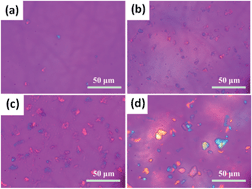
Fig. 6–8 show POM photographs of OMS, OPS and H-POSS based composites, respectively. It is obvious that OMS, OPS and H-POSS all can be dispersed homogeneously in PDMS matrix by solution blending and vulcanization, but their sizes and shapes are different from each other. OMS is hardly seen in the sample M-1, but it forms tiny aggregates when more OMS is added, and most of the aggregates seemingly have inerratic cubic structure, which is comparable with SEM graph of OMS in Fig. 4. And with the rise of OMS loading, though OMS aggregates in PDMS are denser, their sizes almost keep constant. By contrast, OPS aggregates in PDMS matrix are much larger and their shapes are multitudinous. When smaller loading of OPS is incorporated, OPS forms little aggregates; but as the loading of OPS increases, OPS aggregates become larger and larger. As POM graph of P-20 shown in Fig. 7(d), the diameter of OPS aggregates can be as large as 10–15 μm, and also similar to SEM graph of OPS (Fig. 4), the aggregates in composite are observed to have flake-like structures with large surface areas. Regarding H-POSS/PDMS composites, owing to the complete graft of H-POSS onto PDMS chains, aggregates don't appear in the sample H-1. What can be seen in POM graph of H-1 are some black dots which may be cavities caused by the migration of H-POSS. However, in case more H-POSS is added, because of the π–π interactions among phenyls, H-POSS begins to aggregate. In addition, with the loading of H-POSS increases, the aggregates get larger, whereas since the grafting reaction destructs of the integrity of H-POSS crystals, H-POSS aggregates with analogous structures to that in Fig. 4 only appear in the sample H-20 where a majority of H-POSS is free from PDMS matrix.


image file: c4ra07242a-f6.tif
Fig. 6 POM graphs of OMS/PDMS composites: M-1 (a), M-5 (b), M-10 (c) and M-20 (d).

image file: c4ra07242a-f7.tif
Fig. 7 POM graphs of OPS/PDMS composites: P-1 (a), P-5 (b), P-10 (c) and P-20 (d).

image file: c4ra07242a-f8.tif
Fig. 8 POM graphs of H-POSS/PDMS composites: H-1 (a), H-5 (b), H-10 (c) and H-20 (d).

More details can be obtained from XRD patterns of the composites shown in Fig. 9. A broad diffuse scattering peak at around 11.7° which can be detected in all the patterns corresponds to the amorphous structure of PDMS. Furthermore, a small sharp peak at the left side of the broad peak appears upon 5 wt% OPS or H-POSS is added. For H-POSS/PDMS composites, according to Bragg's equation,36 as the small peak shifts to lower angles with the addition of H-POSS, H-POSS crystals tend to be more regular, which is in accordance with POM graphs shown in Fig. 8. Nevertheless, the peak intensity of H-POSS only shows a slight increase with the rise of H-POSS loading, which might stems from the weaker crystallization trend of H-POSS themselve as described in Fig. 5. For OPS/PDMS composites, with the addition of OPS, the intensity of peak of OPS increases ceaselessly because of the aggregation of OPS. What is the most significant is that when 20 wt% OPS is added, some new peaks appear at the right side of the broad peak. The new peaks correspond well with the smaller peaks of OPS (Fig. 5) and confirm the high crystallinity of OPS in the composite. The cases for OMS/PDMS composites are distinctly different. One can observe that peaks of OMS don't emerge until 20 wt% OMS is included. Four sharp peaks can be obviously seen in the XRD patterns of M-20 and the peaks fit well with peaks in XRD patterns of OMS (Fig. 5). Thus, we may conclude that lower than 10 wt% OMS is amorphously dispersed in PDMS matrix, and OMS crystals only exist in composites with more than 10 wt% OMS.


image file: c4ra07242a-f9.tif
Fig. 9 XRD patterns of OMS/PDMS (a), OPS/PDMS (b) and H-POSS/PDMS (c) composites.

3.5. Differences in influence mechanisms of POSSs on crystallization and melting behaviors of PDMS

XRD patterns of M-20, P-20 and H-20 show that crystallization of each kind of POSS is prominent. However, what has been concluded is that the influences of each POSS on crystallization and melting behaviors of PDMS are significantly distinct.

According to the DSC results of OMS/PDMS composites, OMS shows no nucleation effect on crystallization of PDMS. In the sample M-20, OMS forms little aggregates and the packing density of OMS is extraordinarily high. Thus, the tightly packed OMS keeps PDMS chain segments from approaching each other, which results in that PDMS crystals are difficult to take shape, but the formed crystals are very intact.

Nevertheless, as described above, although both OPS and H-POSS can act as nucleating reagents to accelerate the crystallization of PDMS, their influences are significantly different: P-20 shows substantial augment in Tc, crystallization rate and Xc, while H-POSS within a certain improves Tc, crystallization rate and Tm of the composite. OPS crystals are observed to have large surfaces from the POM graph of P-20. During crystallization of PDMS, such surfaces can provide templates for PDMS crystals to grow and the induction effect can appreciably enhance Xc of the composite. Whereas, the surfaces of OPS crystals in OPS/PDMS composites with lower loadings of OPS are not large enough to induce the crystallization of PDMS and contrarily, OPS crystals tend to restrict the regular arrangement of PDMS chain segments. In H-POSS/PDMS, H-POSS in low loadings can graft with vinyls of PDMS. Once more H-POSS is added, because of the weaker crystallization capability of H-POSS compared with OPS, H-POSS crystals couldn't provide enough large surfaces for PDMS crystals, which is similar as OPS/PDMS composites with small OPS loadings. The nucleating effect of H-POSS on crystallization of PDMS expresses as that the mobility of bonded PDMS chains are largely restrained by H-POSS, and the total result is that PDMS crystals become considerable heat-stable but the crystallinity almost keeps unchanged.

4. Conclusion

Three different polyhedral oligomeric silsesquioxanes (POSSs), octamethylsilsesquioxane (OMS), octaphenylsilsesquioxane (OPS) and heptaphenylhydrogensilsesquioxane (H-POSS) were synthesized and then incorporated into polydimethylsiloxane (PDMS) rubber, respectively. Afterwards, the influences of POSSs on crystallization and melting behavior of PDMS, as well as morphologies of POSSs were investigated. Due to the weakest POSS–POSS interactions, OMS crystals are much smaller than the others and the crystal peaks emerge only when 20 wt% OMS is added. The small and closely packed OMS crystals are adverse to the crystallization of PDMS. On the contrary, OPS and H-POSS facilitate the crystallization of PDMS in some cases: as much as 20 wt% OPS tend to markedly increases crystallinity of PDMS, whereas small loadings of H-POSS (lower than 5 wt%) accelerates the crystallization of PDMS, but almost exerts no influence on the crystallinity. The distinctions stem from the morphologies of the composites. Because of the inerratic molecular structure and the strong crystallization capability, when 20 wt% OPS is incorporated, OPS forms giant flake-like crystals with huge surfaces which could provide templates for PDMS crystals to grow. Nevertheless, lower loadings of OPS is not able to form enough large crystals but keeps PDMS chain segments from regularly ranking. For H-POSS/PDMS composites, the formation of PDMS crystals is induced by the physical crosslinking effect of grafted H-POSS on PDMS chain segments. In case more than 5 wt% H-POSS is incorporated, the non-grafted H-POSS cannot induce but decelerate the crystallization of PDMS.

Acknowledgements

The authors thank the National Natural Science Foundation of China (Grant no. 51073097) for financial support.

Notes and references

  1. D. B. Cordes, P. D. Lickiss and F. Rataboul, Chem. Rev., 2010, 110, 2081–2173 CrossRef CAS PubMed.
  2. S. W. Kuo and F. C. Chang, Prog. Polym. Sci., 2011, 36, 1649–1696 CrossRef CAS PubMed.
  3. X. Y. Huang, L. Y. Xie, P. K. Jiang, G. L. Wang and Y. Yin, Eur. Polym. J., 2009, 45, 2172–2183 CrossRef CAS PubMed.
  4. W. Zhang and A. H. E. Müller, Prog. Polym. Sci., 2013, 38, 1121–1162 CrossRef CAS PubMed.
  5. J. F. Brown, J. Am. Chem. Soc., 1965, 87, 4317–4324 CrossRef CAS.
  6. M. M. Sprung and F. O. Guenther, J. Am. Chem. Soc., 1955, 77, 3990–3996 CrossRef CAS.
  7. D. W. Scott, J. Am. Chem. Soc., 1946, 68, 356–358 CrossRef CAS.
  8. R. H. Baney, M. Itoh, A. Sakakibara and T. Suzuki, Chem. Rev., 1995, 95, 1409–1430 CrossRef CAS.
  9. M. G. Voronkov and V. I. Lavrentyev, Top. Curr. Chem., 1982, 102, 199–236 CrossRef CAS.
  10. F. J. Feher, J. Am. Chem. Soc., 1986, 108, 3850–3852 CrossRef CAS.
  11. C. X. Zhang and R. M. Laine, J. Am. Chem. Soc., 2000, 122, 6979–6988 CrossRef CAS.
  12. Y. Liu, Y. Shi and D. Zhang, et al., Polymer, 2013, 54(22), 6140–6149 CrossRef CAS PubMed.
  13. Y. Shi, G. Huang and Y. Liu, et al., J. Polym. Res., 2013, 20(9), 1–11 CAS.
  14. M. C. Tseng and Y. L. Liu, Polymer, 2010, 51, 5567–5575 CrossRef CAS PubMed.
  15. A. Tuteja, W. Choi, M. L. Ma, J. M. Mabry, S. A. Mazzella and G. C. Rutledge, et al., Science, 2007, 318, 1618–1622 CrossRef CAS PubMed.
  16. F. Eckstorff, Y. Z. Zhu, R. Maurer, T. E. Müller, S. Scholz and J. A. Lercher, Polymer, 2011, 52, 2492–2498 CrossRef CAS PubMed.
  17. M. Joshi, B. S. Butola, G. Simon and N. Kukaleva, Macromolecules, 2006, 39, 1839–1849 CrossRef CAS.
  18. Y. Meng, Z. Wei and L. Liu, et al., Polymer, 2013, 54(12), 3055–3064 CrossRef CAS PubMed.
  19. G. Kickelbick, Prog. Polym. Sci., 2003, 28, 83–114 CrossRef CAS.
  20. M. Joshi and B. S. Butola, J. Macromol. Sci., Part C: Polym. Rev., 2004, 44(4), 389–410 CrossRef PubMed.
  21. S. Zheng, F. J. Feher, J. Xiao and R. Z. Jin, Polymer nanocomposites, symposium proceeding series, Materials Research Society, 2002, vol. 734E Search PubMed.
  22. G. Z. Li, L. Wang, H. Toghiani, T. L. Daulton, Jr and C. U. Pittman, Polymer, 2002, 43, 4167 CrossRef CAS.
  23. Z. Qiu and H. Pan, Compos. Sci. Technol., 2010, 70, 1089–1094 CrossRef CAS PubMed.
  24. H. Pan and Z. Qiu, Macromolecules, 2010, 43, 1499–1506 CrossRef CAS.
  25. J. Yu and Z. Qiu, ACS Appl. Mater. Interfaces, 2011, 3, 890–897 CAS.
  26. K. Lee and Y. Chang, Polym. Int., 2013, 62, 64–70 CrossRef CAS PubMed.
  27. W. Zhou, S. Yuan, L. Tan, Y. Chen and Y. Huang, Polym. Eng. Sci., 2012, 52, 2063–2070 CAS.
  28. M. J. Fernández, M. D. Fernández and M. Cobos, RSC Adv., 2014, 4(41), 21435–21449 RSC.
  29. E. L. Heeley, D. J. Hughes, Y. El Aziz, P. G. Taylor and A. R. Bassindale, Eur. Polym. J., 2014, 51, 45–56 CrossRef CAS PubMed.
  30. M. Joshi, B. S. Butola, G. Simon and N. Kukaleva, Macromolecules, 2006, 39, 1839–1849 CrossRef CAS.
  31. L. Liu, M. Tian, W. Zhang, L. Zhang and J. E. Mark, Polymer, 2007, 48, 3201–3212 CrossRef CAS PubMed.
  32. D. Zhang, Y. Liu, Y. Shi and G. Huang, RSC Adv., 2014, 4(12), 6275–6283 RSC.
  33. E. S. Park and H. W. Ro, et al., Chem. Mater., 2008, 20, 1548–1554 CrossRef CAS.
  34. B. Handke, W. Jastrzebski, W. Mozgawa and A. Kowalewska, J. Mol. Struct., 2008, 887, 159–164 CrossRef CAS PubMed.
  35. K. Olsson and C. Gronwall, Ark. Kemi, 1961, 17, 529–540 CAS.
  36. Z. S. Mo, Structure of Crystalline Polymer and X-ray Diffraction [M], Science Press, PRC, 2003, p. 232 Search PubMed.

This journal is © The Royal Society of Chemistry 2014
Click here to see how this site uses Cookies. View our privacy policy here.