Excellent electrochemical performance of tin monosulphide (SnS) as a sodium-ion battery anode

Prasit Kumar Dutta, Uttam Kumar Sen and Sagar Mitra*
Electrochemical Energy Laboratory, Department of Energy Science and Engineering, Indian Institute of Technology Bombay, Powai, Mumbai 400076, India. E-mail: sagar.mitra@iitb.ac.in; Fax: +91-22-2576-4890; Tel: +91-22-2576-7849

Received 17th June 2014 , Accepted 26th August 2014

First published on 26th August 2014


Abstract

Tin monosulphide is synthesized by a simple wet chemical synthesis approach. The as-prepared tin monosulphide has been used as anode in Na-ion battery without any in situ conductive carbon or graphene coating, and the electrode exhibits a high reversible sodium reversible capacity of ∼500 mA h g−1 at a discharge rate of 125 mA g−1. It also demonstrates excellent high rate performance (i.e. 390 and 300 mA h g−1 at 500 and 1000 mA g−1 current density respectively) and cycle stability without the addition of any expensive additive stabilizer, such as fluoroethylene carbonate (FEC), in comparison to those in current literature.

Introduction

It is certain that energy storage technology will be a determining technology to solve the present fuel and environmental crisis in future. Among all the energy storage technologies, battery technology plays an important role in the incorporation of renewable sources to the electricity sector. The main player in battery technology, lithium battery, is somewhat restricted due to high ore processing cost, fabrication cost and availability.1 On the other hand, sodium or sodium-ion battery could be a great player in the large scale sector due to its high abundance, low processing cost and suitable redox potential compared to that of Li (E° value for Li/Li+ = 3.05 V and for Na/Na+ = 2.71 V vs. SHE at 298 K, 1 M, 1 atm). Recent trends shows that electrochemical cells based on sodium hold promise as large scale power sources because of their low cost and widespread geological distribution of sodium mines.2 However, the practical implementation of a sodium ion battery is limited due to its low energy density and poor cyclability, which is mainly attributed to the large ionic radius of sodium ion.3 In comparison to the lithium ion, the radius of a sodium ion is 55% larger,4 which makes it difficult to diffuse in most of the layered transition metal based oxide cathodes (sluggish sodium kinetics) and also causes large structural changes in the host electrodes.5 This problem is more acute in the case of anodes, where the intercalation of sodium ion in any form of graphite is almost impossible, causing sodium electroplating on the surface rather than intercalation into basal planes of carbon electrode.6

In the present scenario, utmost consideration for sodium-ion battery anode materials research is towards finding a sustainable, low-cost, non-toxic, non-explosive system to prepare a commercially viable sodium-ion battery. In current literature, many electrode materials, such as hard carbon,6 titanium dioxide,7 tin,8,9 antimony,10 tin–tin sulphide–carbon composite,9 tin disulphide–graphene composite,11 red phosphorous–carbon composite,12 and sodium teraphthalate,13 has been used and considered to be a promising alternative anode to graphite, but most of them suffer from rate capability and cyclic stability issues. In recent studies, we have witnessed that alloy-based anodes, such as Sn,8,9,14 Sb,10 Pb15 and P,12 systems are the most promising alternative due to their high energy densities. However, these systems suffer from poor cyclic performance because of huge volume changes occurring during the alloying–dealloying reaction. Wang et al. have experimentally found that Sn can expand to 420% by volume after reacting with sodium and forming a Na15Sn4 phase causing electrode destabilization.16 Apart from poor cyclic stability, the sluggish diffusion of Na-ion into solid medium at ambient temperature has a high barrier to overcome before its penetration to large scale applications.

In search of high capacity, high rate capable, safe and low cost anode materials, we have identified tin mono sulphide (SnS) as a conversion-cum-alloy based anode material for sodium ion batteries. Tin alone can store a capacity of about 847 mA h g−1 (theoretical) due to the formation of a sodium rich Na15Sn4 phase, whereas the tin sulphide (SnS) phase can store a capacity of about 1022 mA h g−1 (theoretical) with respect to Na. In the current study, we have prepared tin mono sulphide nanoparticles with occasional nanorods using a simple wet chemical synthesis route at room temperature, followed by annealing; with SnCl2 as tin source and thio-acetamide as sulphur source, respectively. The bare SnS material has been used as electro-active material without any conductive coating and tested in half-cell configuration against Na using 1 M NaClO4 in propylene carbonate (without any additive stabilizer) as electrolyte. In the current study, sodium alginate has been used as an interactive binder17,18 to buffer such high volume expansion during alloying–dealloying reactions and observed high stability in electrode performance. The electrode material exhibits 325 mA h g−1 reversible capacity even after thirty cycles at 125 mA g−1 current rate. To our best knowledge, we are the first to report synthesized bare SnS as sodium-ion battery anode with excellent rate capability compare to existing literature.

Experimental section

Synthesis of SnS

A simple wet chemical synthesis process was adopted19 to prepare SnS nano-rods. In a typical synthesis process, ∼3.0 mM of SnCl2·2H2O (99%, Merck, India) was dissolved in 5 ml of acetone (99%, Merck, India). Then, 7.5 ml of triethanolamine solution was added in an equal amount of deionised water, and the diluted triethanolamine solution was added to SnCl2 solution under constant stirring. Finally, 5 ml 1 M thioacetamide (99%, Spectrochem, India) solution was added followed by the addition of 25 ml 4 M ammonia solution (28%, Merck, India). The reaction mixture was allowed to stir around 16 hours in closed beaker at room temperature. Dark brown precipitate was obtained, which was further centrifuged, washed for several times with deionised water, dried at 60 °C in hot air oven for 12 hours and finally annealed at 500 °C for 5 hours under N2 atmosphere.

Material characterisation

Material characterisation was performed by powder X-ray diffraction (XRD) measurements at 25 °C using Philips X'-Pert Diffractometer with Cu Kα radiation (λ = 1.5418 Å) at 40 kV and 40 mA. Morphological analysis was carried out using JEOL-2100F field emission gun transmission electron microscope (FEG-TEM). For TEM analysis, a well-dispersed solution was prepared by adding a little amount of SnS powder in isopropyl alcohol and sonicated for 30 min. One drop of dispersed solution was taken on TEM grid to obtain high resolution images at the best operating condition. Energy dispersive X-ray analysis (EDAX) was performed to estimate the atomic proportion of the as-synthesized material.

Electrochemical cell fabrication and measurements

Galvanostatic charge–discharge tests were carried out using lab scale Sweagelok type cells having a cell configuration of Na|NaClO4|SnS. Electrochemical cells were assembled in an argon-filled glovebox (Lab Star, Mbraun, Germany) with controlled moisture and oxygen concentration around 1 ppm. Sodium foil was used as a counter as well as reference electrode. For electrolyte preparation, sodium perchlorate (NaClO4) salt was dissolved in propylene carbonate (PC) to obtain a 1 M NaClO4 solution, which was used as an electrolyte in this study. The electrolyte preparation was performed inside the argon filled glovebox. Borosilicate glass microfiber filters (Whatman) were used as a separator. The electrodes were prepared using SnS as the active material, carbon black (Super C-65, Timcal, Switzerland) as conductive additive, and a polymeric binder (sodium alginate) with an overall ratio of 3[thin space (1/6-em)]:[thin space (1/6-em)]1[thin space (1/6-em)]:[thin space (1/6-em)]1 (by wt). Slurry was prepared by adding a hand-grinded mixture of SnS and carbon in sodium alginate jellified with few drops of deionized water under constant stirring for 4 h at room temperature. This slurry was then cast on Cu foil using a doctor's blade and the electrode was dried at 60 °C under vacuum for 12 h. Cyclic voltammetry (CV) profile was obtained by measuring iV response at a scan rate of 0.02 mV s−1 within a potential window of 0.1–2.5 V vs. Na/Na+ using Biologic VMP-3 potentiostat/galvanostat. The electrochemical charge–discharge experiments were performed using Arbin Instrument, USA (BT2000 model) at various constant current rates. Potentiostatic electrochemical impedance spectroscopy (PEIS) was performed for the first discharge and charge cycle at ten different points within a frequency range of 1 MHz to 0.1 Hz and with voltage amplitude of ΔV = 5 mV using Bio-logic VMP-3 instrument. For EIS experiments, charge–discharge was carried out at a constant current density of 50 mA g−1. All the electrochemical measurements were obtained at a constant temperature of 20 °C.

Results and discussion

Structural characterization

The X-ray diffraction (XRD) pattern of SnS powder is shown in Fig. 1a, which is indexed as the orthorhombic phase of SnS (JCPDS card no. 75-2115). It is noteworthy to specify that the as obtained SnS is not 100% phase pure but contain some impurities of SnSx.20 High-resolution transmission electron microscopy instrument was used to study the microstructure of SnS sample. FEG-TEM images (shown in Fig. 1b and d–g) illustrate that the nanoparticle with occasional nanorod type morphology of SnS was obtained with a particle size of <100 nm. The high resolution images (Fig. 1d and e) identify that the well-defined layered structure of SnS having an interlayer distance of 0.312 nm for (210) planes and 0.252 nm for (211) planes, has been observed. The selected area electron diffraction (SAED) pattern shown in Fig. 1c indicates the planes corresponding to (0 1 1), (1 1 1), (4 1 1) planes of orthorhombic SnS crystal. EDAX analysis (Fig. S1 in ESI) shows that 1[thin space (1/6-em)]:[thin space (1/6-em)]1 atomic ratio of Sn and S is present in the as-prepared SnS sample.
image file: c4ra05851h-f1.tif
Fig. 1 (a) XRD pattern, (b and d–g) FEG-TEM images, (c) selected area electron diffraction (SAED) pattern (corresponding to (b)) of the as-synthesized SnS.

Electrochemical performance

The reaction of SnS with sodium is complicated because it undergoes conversion followed by alloying reaction with sodium. In this system both Sn and S undergo an alloying reaction with sodium. Therefore, a careful investigation was carried out to understand the sodium storage mechanism in SnS. Fig. 2a shows the cyclic voltammogram of the SnS electrode performed in a voltage window of 0.1–2.5 V vs. Na/Na+ at voltage scan of 0.02 mV s−1. During the first cathodic sweep, two prominent peaks were observed at 0.75 V and 0.2 V vs. Na/Na+, respectively. According to literature, the peak at 0.75 V is associated with both the conversion reaction (SnS to Sn and Na2S) as well as the alloying reaction (with Sn3,8). Because both the conversion reaction of SnS and the alloying reaction of Sn occurred at ∼0.7 V vs. Na/Na+, it is difficult to distinguish the conversion and alloying peaks. Furthermore, the peak at 0.2 V was due to the reaction between Na and NaSn alloy. The alloying reaction between Na and Sn is known to be a multistep reaction.16 In the first step (at ∼0.7 V), Sn forms an alloy with Na and forms NaSn5. While at ∼0.2 V, more Na was incorporated to form Na9Sn4.3,16 During the anodic sweep, three prominent peaks were observed at 0.2 V, 0.65 V and 1.0 V vs. Na/Na+ along with two small humps at 1.3 V and 1.7 V vs. Na/Na+ respectively. The peaks at 0.2 V and 0.65 V were due to the two step dealloying reaction from NaSnx, whereas the peak at 1.0 V was due to the formation of SnSx.21 Small humps at 1.3 V and 1.7 V were due to the formation of polysulphur form Na2Sx.22
image file: c4ra05851h-f2.tif
Fig. 2 (a) Cyclic voltammetry at a scan rate of 0.02 mV s−1 within the potential range of 0.1 to 2.5 V, (b) charge–discharge profile at current rate of 125 mA g−1, (c) cyclic performance at 125 mA g−1 and (d) power cycle performance of Na|NaClO4|SnS half-cell within the potential range of 0.1 to 2 V.

It was found that after the 1st cycle, free sulphur and metal nanoparticles were present in the system, which were utilized to ensnare sodium. A similar kind of mechanism was also observed in other metal sulphide based anodes.21,23–25 The as-obtained CV profile shown in Fig. 2a demonstrates the change in the voltammogram from the 1st cycle to the remaining cycles. During the second cathodic sweep, three prominent redox peaks were observed at 1.1 V, 0.7 V and at 0.2 V vs. Na/Na+, respectively. The peak at 1.1 V was due to the reaction between Na and polysulphur to form Na2Sx, whereas the peaks at 0.7 V and 0.2 V were due to the alloying reaction between sodium and tin. During the reverse process (2nd anodic sweep), four peaks were observed at 0.2 V, 0.65 V, 1.3 V and 1.7 V vs. Na/Na+, respectively. The intense peaks at 0.2 V and 0.65 V were due to the dealloying reaction of NaSnx reaction. The peaks at 1.3 V and 1.7 V were due to the formation of polysulphur. Similar observations were noticed during the charge–discharge cycling shown in Fig. 2b.

Rate performance test

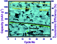
Fig. 2b–d shows galvanostatic charge–discharge profiles that were carried out at constant as well as variable current densities within the potential range of 2.0 to 0.1 V vs. Na/Na+. Initial discharge capacity of ∼775 mA h g−1 was obtained at a discharge rate of 125 mA g−1 (∼C/8 rate), while a reversible capacity of ∼500 mA h g−1 was achieved after few charge–discharge cycles. At the end of 30 cycles, a discharge capacity ∼370 mA h g−1 was retained, which is about 74% of the reversible capacity of 1st cycle. A high coulombic efficiency of around 98% was estimated for the initial 15 cycles, which indicates a better performance of the electrode. After 15 cycles, a gradual declining nature in discharge capacity as well as the coulombic efficiency was observed, which was mainly due to material loss caused by volume expansion related issues such as the cracking and pulverization of the electrode. Power cycle performance shown in Fig. 2c describe that at a high rate of 500 mA g−1 and 1000 mA g−1, a reversible capacity of 390 and 300 mA h g−1 has been achieved with bare electrode material. As per the best of our knowledge, there are no matching results available in the literature that show bare SnS was used as an anode for sodium-ion batteries to compare the rate capability. A comparison of electrochemical performance between electrodes with different composition of 60[thin space (1/6-em)]:[thin space (1/6-em)]20[thin space (1/6-em)]:[thin space (1/6-em)]20 and 70[thin space (1/6-em)]:[thin space (1/6-em)]20[thin space (1/6-em)]:[thin space (1/6-em)]10 was performed and is shown in Fig. S2 in the ESI. The morphology of the electrode after charge–discharge cycle was also investigated (Fig. S3 & S4 in ESI), which shows that the initial morphology was changed after 30 cycles.

To further understand the interfacial properties, an electrochemical impedance spectroscopy (EIS) experiment was carried out (Fig. 3a and b) to realize the change in the electrode reaction. During the first discharge–charge process, EIS was obtained at five different points (Fig. 3c) in each half cycle. It was observed that charge transfer resistance of the electrode was increased from OCV to 0.8 V which may be because of Na insertion in the SnS lattice. Electrode impedance was even increased upon moving to the conversion region and then mostly stable thereafter. During the oxidation process (charge reaction) three process were observed, first dealloying of Na from NaxSn followed by formation of SnSx and finally formation of polysulphur from Na2S. The dealloying reaction occurred in two steps at ∼0.3 and ∼0.7 V. Thus, when EIS was taken at 0.5 V two semicircles were observed due to presence of two phasic components. At the end the dealloying reaction (at 0.8 V) EIS shows that the second semicircle disappeared. After 0.8 V, SnSx was formed from Sn and Na2S, which was evident by the change in the charge transfer resistance. An increasing trend in the charge transfer resistance value was found at 1.2 V due to removal of metallic nanoparticles from the system. Finally a two-step polysulphur formation reaction occurred at ∼1.4 V and ∼1.6 V. Therefore, at 1.5 V the possibility of the presence of two phasic components was indicated by the evolution of an extra semicircle, which disappeared after the completion of the reaction (at 2.0 V).


image file: c4ra05851h-f3.tif
Fig. 3 EIS spectra of SnS electrode at different potential during (a) 1st discharge and (b) charge process, (c) charge–discharge profile of 1st cycle at 50 mA g−1 along with potential points where EIS were taken and (d) the equivalent circuit used to fit the EIS spectra.

Conclusions

In summary, we have successfully synthesized a nanostructured SnS electrode via a simple solution based technique. In the current study, we have not applied any conducting coating to the sample for improving the electrode kinetics further and used directly as an anode material for sodium ion battery. A stable electrochemical performance was achieved using 1 M NaClO4 in PC without any additive. High reversible capacity due to conversion and alloying reaction of the SnS based electrode was demonstrated using constant current charge–discharge and power cycling. The bare SnS electrode showed excellent rate performance with a reversible capacity of ∼370–520 mA h g−1 at a discharge rate of 125 mA g−1. The good electrochemical performance is attributed to the unique morphology with larger interlayer distance and easy fuelling of electrons at the electrode–electrolyte interface. Electrochemical impedance spectroscopy and slow scan cyclic voltammetry experiments were used to gain insights into the complicated reaction mechanism with sodium. Both the experiments have come to a same conclusion and elucidate the mechanism. Furthermore, we used sodium-alginate binder to stabilize the performance. The increase in rate performance may be further improved by using an optimized electrolyte and altering the electrode fabrication technology.

Acknowledgements

The authors acknowledge the financial support provided by Solar Energy Research Institute for India and the United States (SERIIUS) funded by the U.S. Department of Energy (Office of Science, Office of Basic Energy Sciences, and Energy Efficiency and Renewable Energy, Solar Energy Technology Program, under Subcontract DEAC36-08GO28308 to the National Renewable Energy Laboratory.

Notes and references

  1. B. Scrosati, Nature, 2011, 473, 448 CrossRef CAS.
  2. G. D. Aumann and J. T. Emlen, Nature, 1965, 208, 198 CrossRef CAS.
  3. V. L. Chevrier and G. Ceder, J. Electrochem. Soc., 2011, 158, A1011 CrossRef CAS PubMed.
  4. L. Xiao, Y. Cao, J. Xiao, W. Wang, L. Kovarik, Z. Nie and J. Liu, Chem. Commun., 2012, 48, 3321 RSC.
  5. S.-W. Kim, D.-H. Seo, X. Ma, G. Ceder and K. Kang, Adv. Energy Mater., 2012, 2, 710 CrossRef CAS PubMed.
  6. D. A. Stevens and J. R. Dahn, J. Electrochem. Soc., 2000, 147, 1271 CrossRef CAS PubMed.
  7. H. Xiong, M. D. Slater, M. Balasubramanian, C. S. Johnson and T. Rajh, J. Phys. Chem. Lett., 2011, 2, 2560 CrossRef CAS.
  8. Y.-M. Lin, P. R. Abel, A. Gupta, J. B. Goodenough, A. Heller and C. B. Mullins, ACS Appl. Mater. Interfaces, 2013, 5, 8273 CAS.
  9. L. Wu, X. Hu, J. Qian, F. Pei, F. Wu, R. Mao, X. Ai, H. Yang and Y. Cao, J. Mater. Chem. A, 2013, 1, 7181 CAS.
  10. J. Qian, Y. Chen, L. Wu, Y. Cao, X. Ai and H. Yang, Chem. Commun., 2012, 48, 7070 RSC.
  11. X. Xie, D. Su, S. Chen, J. Zhang, S. Dou and G. Wang, Chem.–Asian J., 2014, 9, 1611 CrossRef CAS PubMed.
  12. Y. Kim, Y. Park, A. Choi, N.-S. Choi, J. Kim, J. Lee, J. H. Ryu, S. M. Oh and K. T. Lee, Adv. Mater., 2013, 25, 3045 CrossRef CAS PubMed.
  13. L. Zhao, J. Zhao, Y.-S. Hu, H. Li, Z. Zhou, M. Armand and L. Chen, Adv. Energy Mater., 2012, 2, 962 CrossRef CAS PubMed.
  14. S. Komaba, Y. Matsuura, T. Ishikawa, N. Yabuuchi, W. Murata and S. Kuze, Electrochem. Commun., 2012, 21, 65 CrossRef CAS PubMed.
  15. M. Mortazavi, J. Deng, V. B. Shenoy and N. V. Medhekar, J. Power Sources, 2013, 225, 207 CrossRef CAS PubMed.
  16. J. W. Wang, X. H. Liu, S. X. Mao and J. Y. Huang, Nano Lett., 2012, 12, 5897 CrossRef CAS PubMed.
  17. P. S. Veluri and S. Mitra, RSC Adv., 2013, 3, 15132 RSC.
  18. I. Kovalenko, B. Zdyrko, A. Magasinski, B. Hertzberg, Z. Milicev, R. Burtovyy, I. Luzinov and G. Yushin, Science, 2011, 334, 75 CrossRef CAS PubMed.
  19. A. J. Ragina, K. V. Murali, K. C. Preetha, K. Deepa and T. L. Remadevi, J. Mater. Sci.: Mater. Electron., 2012, 23, 2264 CrossRef CAS PubMed.
  20. A. M. Tripathi and S. Mitra, RSC Adv., 2014, 4, 10358 RSC.
  21. B. Qu, C. Ma, G. Ji, C. Xu, J. Xu, Y. S. Meng, T. Wang and J. Y. Lee, Adv. Mater., 2014, 26, 3854 CrossRef CAS PubMed.
  22. J. Park, J.-S. Kim, J.-W. Park, T.-H. Nam, K.-W. Kim, J.-H. Ahn, G. Wang and H.-J. Ahn, Electrochim. Acta, 2013, 92, 427 CrossRef CAS PubMed.
  23. D. Su, S. Dou and G. Wang, Chem. Commun., 2014, 50, 4192 RSC.
  24. X. Fang, X. Guo, Y. Mao, C. Hua, L. Shen, Y. Hu, Z. Wang, F. Wu and L. Chen, Chem.–Asian J., 2012, 7, 1013 CrossRef CAS PubMed.
  25. X. Fang, C. Hua, X. Guo, Y. Hu, Z. Wang, X. Gao, F. Wu, J. Wang and L. Chen, Electrochim. Acta, 2012, 81, 155 CrossRef CAS PubMed.

Footnote

Electronic supplementary information (ESI) available. See DOI: 10.1039/c4ra05851h

This journal is © The Royal Society of Chemistry 2014
Click here to see how this site uses Cookies. View our privacy policy here.