Improved cycling performance of a silicon anode for lithium ion batteries using carbon nanocoils

Liyong Wangab, Quangui Guo*a, Junzhong Wanga, Hai Liab, Guizhen Wangbc, Jinhua Yangab, Yan Songa, Yong Qinc and Lang Liua
aKey Laboratory of Carbon Materials, Institute of Coal Chemistry, Chinese Academy of Sciences, Taiyuan 030001, China. E-mail: qgguo@sxicc.ac.cn; Fax: +86 351 4084 106
bUniversity of Chinese Academy of Sciences, Beijing 100049, China
cState Key Laboratory of Coal Conversion, Institute of Coal Chemistry, Chinese Academy of Sciences, Taiyuan 030001, China

Received 7th June 2014 , Accepted 11th August 2014

First published on 13th August 2014


Abstract

We demonstrate a new kind of silicon (Si)-based anode architecture consisting of Si nanoparticles and carbon nanocoils (CNCs). In such a hybrid structure, the conductive three-dimensional interpenetrating network of the CNCs can enhance the structural integrity of the electrode. Also, the CNCs afford a conductive network of lithium ion and electron pathways in the hybrids, thereby enabling efficient transport of electrons and the diffusion of lithium ions upon charging–discharging process. As a result, the hybrids exhibit much-improved cycling performance.

Lithium ion batteries (LIBs) with high energy and high power density are required to power portable electronic devices.1–3 The application of LIBs will be indispensable in the future.4,5 Silicon (Si) and carbon material are the topical anode materials for LIBs. Si is a promising anode material for LIBs due to its low working potential (about 0.5 V vs. Li/Li+) and the highest known theoretical lithium storage capacity (about 4200 mA h g−1).6 However, Si usually undergoes an enormous volume expansion of nearly 300% when alloying with Li to form Li15Si4 phase at room temperature. Si cannot tolerate the stresses associated with these lithiation/delithiation cycles and crumbles, resulting in fast battery failure.7 Compared with Si, carbon material has low theoretical lithium storage, but little volume change during the cycling. To further study the lithium storage of carbon material, many methods have been tried. Fully fluorinated graphene nanosheets (fluorine content 49.7 at%) as anode material can deliver a high reversible capacity of 780 mA h g−1, which is higher than that of graphite.8 To the pure carbon material, one-dimensional carbon nanofiber grown on the two-dimensional graphene sheets as anode material shows high reversible capacity of 667 mA h g−1, which is higher than that of pure graphene.9 The carbon materials with different structures (porous graphene, hollow carbon fiber, carbon sphere etc.)10–19 are also applied in LIBs. However, Si should still have good prospect in LIBs due to their huge lithium storage. To get better lithium storage, many researchers have carried out a lot of profound work. For example, the Si pomegranate as anode material affords high reversible capacity of 2350 mA h g−1 after 1000 cycles.20 In this structure, Si nanoparticles were first encapsulated by a conductive carbon layer that leaves enough room for expansion and extraction. An ensemble of these nanoparticles is then encapsulated by a thick carbon layer as electrolyte barrier. This hierarchical design makes them like pomegranate, which leads to superior cyclability after 1000 cycles. Si with other different size and hierarchical structure design has also been studied as anode material, which exhibited good lithium storage for LIBs.6,21 Bringing carbon material in LIBs with complicated design can improve the cycling performance of Si.

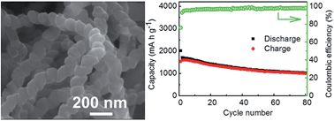
Carbon nanocoils (CNCs) are extraordinary in structure due to their three-dimensional helical nature.22,23 So far, researchers studying CNCs have found many outstanding properties, such as light weight, high electrical conductivity,24 large surface area and unique superelasticity.25 Here, we use CNCs as a new carbon matrix to improve the electrochemical performance of Si anode for LIBs for the first time. Also, the method we adopted is very simple, by directly mixing the Si nanoparticles with CNCs without complicated structure design. The CNCs were synthesized by chemical vapor deposition26 and annealed at 3073 K in Ar atmosphere. The quasi-one-dimensional chiral nanostructure and morphology can be clearly observed by scanning electron microscopy (SEM) and transmission electron microscopy (TEM), as shown in Fig. 1. A lot of CNCs are randomly stacked to form three-dimensional porous and interpenetrating network, which can provide abundant free space.


image file: c4ra05444j-f1.tif
Fig. 1 CNCs annealed at 3073 K in Ar atmosphere: (a) SEM image, (b) TEM image, and (c) high resolution TEM image (inset shows the electron diffraction pattern).

Small commercial Si nanoparticles (<100 nm) have good robustness and crystallinity coated with 7–8 nm of amorphous SiO2 (Fig. 2a and b). We combine Si nanoparticles with CNCs to get a composite as an anode for LIBs. The Si/CNCs composite was prepared by simple mixing of Si nanoparticles and CNCs (1[thin space (1/6-em)]:[thin space (1/6-em)]1 by weight) in ethanol assisted by bath sonication. Then the mixture was slowly dried in air at room temperature with a constant stir. The working electrodes consisted of active material, acetylene black and sodium carboxymethyl cellulose binder (70[thin space (1/6-em)]:[thin space (1/6-em)]20[thin space (1/6-em)]:[thin space (1/6-em)]10 by weight). CR 2016-type coin cells were assembled in a glovebox with Ar atmosphere. Li foil was used as the counter electrode and reference electrode, with microporous polypropylene film (Celgard 2400) as the separator. The electrolyte was composed of 1 M LiPF6 in ethylene carbonate–dimethyl carbonate (1[thin space (1/6-em)]:[thin space (1/6-em)]1 by volume) and 5 vol% vinylene carbonate. The cells were galvanostatically discharged and charged using a battery test system (LAND CT 2001A model, Wuhan Jinnuo Electronics Ltd.) in the voltage range of 0.01–2 V at room temperature. As expected, it was found the cycling performance was remarkably improved compared to bare Si anode. Before lithiation/delithiation process, the CNCs can be clearly seen in the hybrid (Fig. 2c). The morphology of Si/CNCs composite was observed by TEM, showing Si nanoparticles and CNCs clearly in Fig. 2d. The energy-dispersive X-ray spectroscopy analysis shows that the main elements are Si and C, which is in accord with the presence of both Si and CNCs in the hybrid, while the small O signal can be related to the amorphous SiO2. The d002 space of the CNCs is measured to be 0.3411 nm by X-ray diffraction analysis (Fig. 2e), which is indicative of the slightly turbostratic structure. Fig. 2f shows a soft and uniform solid electrolyte interface (SEI) layer coated onto CNCs and Si merged in the anode material after lithiation/delithiation for 100 cycles.


image file: c4ra05444j-f2.tif
Fig. 2 (a and b) Si nanoparticles: (a) SEM image, (b) TEM image (inset shows the electron diffraction pattern). (c and d) Si/CNCs: (c) SEM image, (d) TEM image (insets show electron diffraction pattern and energy-dispersive X-ray spectroscopy). (e) X-ray diffraction pattern of Si/CNCs. (f) SEM image of Si/CNCs electrode after charge–discharge for 100 cycles.

A typical cyclic voltammetry measurement of Si/CNCs electrode in the voltage range of 0.01–2.0 V at a sweep rate of 1 mV s−1 is shown in Fig. 3a. In the first cathodic half-cycle, the cathodic peak is observed at 0.94 V, as shown in the inset in Fig. 3a. It possibly results from the formation of SEI film that leads to an initial irreversible capacity.27,28 The discharge current starts to increase at 0.30 V and then becomes large. In the case of the anodic scan, there are two anodic peaks appearing at 0.42 and 0.61 V, corresponding to the dealloying process of LixSi →Si + xLi+ + xe. After fifty cycles, there is no significant shift, suggesting its good cycling performance.


image file: c4ra05444j-f3.tif
Fig. 3 (a) Cyclic voltammetry curves of Si/CNCs (inset shows the magnified curve for marked part). (b) Charge–discharge profiles of the anode of CNCs annealed at 3073 K. (c) Charge–discharge profiles of the anode of Si/CNCs (inset shows profiles of the Si anode). (d) Nyquist plots of the electrodes of Si/CNCs and pure Si (inset shows the magnified curve in the marked part).

The discharge–charge curves of CNCs, Si and Si/CNCs are shown in Fig. 3. The pure CNCs delivers a first discharge capacity of 401 mA h g−1 and a first charge capacity of 273.7 mA h g−1 at a current density of 50 mA g−1 (Fig. 3b). In the case of pure Si electrode, its initial discharge and charge capacity are 3448 and 2994 mA h g−1, respectively, at a current density of 100 mA g−1 (Fig. 3c). The Si/CNCs delivers a first discharge capacity of 2014.8 mA h g−1 and a first charge capacity of 1533.9 mA h g−1 at a current density of 200 mA g−1 (Fig. 3c). This indicates that both CNCs and Si nanoparticles contribute to the initial charge–discharge capacity. It can be clearly seen that a single and long flat potential plateau with onset potential of ca. 0.12 V during the first discharge curve is observed. The Si and Si/CNCs electrodes display similar voltage profiles although Si/CNCs composite contains half mass of CNCs, which indicates that Si is still dominative for the anode capacity. Judging from the first several cycles of the two electrodes, the Si/CNCs electrode exhibits much better cyclability.

The enhanced electrical conductivity of the Si/CNCs over Si was verified by electrochemical impedance spectroscopy (EIS) measurements shown in Fig. 3d. The Si has larger impedance than that of the Si/CNCs due to its poor electrical conductivity and volume change. The EIS spectra of Si/CNCs consist of two semicircles and a linear diffusion drift. The first semicircle may result from the formation of the SEI. The second semicircle is probably because of the interfacial charge transfer impedance. The short diffusion tail suggests that the CNCs' conductive network facilitates the diffusion and transport of lithium ions between the electrode and the electrolyte, thus reducing the lithium ion diffusion resistance. In addition, we have measured the electrical resistivity of Si and the Si/CNCs composite by four-probe approach. The electrical resistivity of Si is too large to exceed the range of equipment (10−5 to 105 Ω cm) due to poor electrical conductivity. The electrical resistivity of Si/CNCs composite is 29.0 Ω cm, which is much lower than that of Si. The enhancement of the electrical conductivity by CNCs addition measured by four-probe approach is in accordance with the EIS measurements.

The Si/CNCs electrode maintains a reversible capacity of 997.3 mA h g−1 after 80 cycles at a current density of 200 mA g−1, corresponding to the reversible capacity retention of 65% (Fig. 4a). The Si/CNCs electrode reaches a steady coulombic efficiency higher than 95% without obvious shift during the cycling except for the initial Coulombic efficiency of 76.1%. In contrast, bare Si electrode only delivers a reversible capacity of 391.5 mA h g−1 at a low current density of 100 mA g−1 after ten cycles, with only 13% retention in capacity (Fig. 4b). The Si/CNCs electrode is also allowed to discharge–charge at different higher current densities (Fig. 4c). The Coulombic efficiency is higher than 94% and quite steady during the cycling at different current densities except for the initial Coulombic efficiency of 74.1%. A high current density (1 A g−1) is imposed on Si/CNCs electrode, and its corresponding reversible capacity is very steady with Coulombic efficiency higher than 99%. The Si nanoparticles used in this work are covered by oxide layer (>2 nm), which leads to poor electrical conductivity. With the decrease of the size of the Si nanoparticle and the thickness of SiO2, the electrochemical performance should be improved. In,28 the Si nanoparticles (5–20 nm) with very thin oxide layer were used as anode material. After 50 cycles, they exhibited a good final capacity of 525 mA h g−1. It was higher than that of the pure Si nanoparticles used in our work (the final capacity of 391.5 mA h g−1 after 10 cycles). After bringing the CNCs into the anode material, the Si/CNCs composite exhibited a final capacity of 997.3 mA h g−1 after 80 cycles, which was higher than that of the Si nanoparticles (5–20 nm). So the CNCs play an important role in improving the cycling performance of Si.


image file: c4ra05444j-f4.tif
Fig. 4 Cycle performance: (a) Si/CNCs, (b) pure Si. (c) Rate capability of Si/CNCs.

In order to further understand the electrochemical performance of Si/CNCs electrode, the structure morphology of the electrode during the alloying–dealloying process was studied by SEM. After first discharge process, the CNCs can be clearly seen, which interpenetrate each other and form a hollow three-dimensional structure, and Si nanoparticles disperse well inside (Fig. 5a and b). The CNCs interpenetrate in the whole anode material after the first discharge–charge process, and around the CNCs are the Si nanoparticles (Fig. 5c). This not only enhances the structural integrity of the electrode, but also improves the integral electrical conductivity.


image file: c4ra05444j-f5.tif
Fig. 5 SEM images of Si/CNCs anode: (a) discharged for the first time, (b) the magnified marked part in (a), (c) discharged–charged for the first cycle.

In conclusion, CNCs' network can enhance the structural integrity of the electrode and form electrical conductive network for hybrids, which can improve the cycling performance of Si anode for LIBs. The CNCs could be also extended to other fascinating electrode material systems that undergo volume change and have poor electrical conductivity.

Acknowledgements

This work was supported by the National Natural Science Foundation of China (21373255, 51362010), the Nature Science Foundation of Hainan Province (514207, 514212), the Scientific Research Projects of Colleges and Universities of Hainan Province (HNKY2014-14) and Young Teacher Fund of Hainan University (qnjj1171).

References

  1. P. G. Bruce, B. Scrosati and J. M. Tarascon, Angew. Chem., Int. Ed., 2008, 47, 2930 CrossRef CAS PubMed.
  2. A. S. Arico, P. Bruce, B. Scrosati, J. M. Tarascon and W. van Schalkwijk, Nat. Mater., 2005, 4, 366 CrossRef CAS PubMed.
  3. H. G. Jung, M. W. Jang, J. Hassoun, Y. K. Sun and B. Scrosati, Nat. Commun., 2011, 2, 516 CrossRef PubMed.
  4. B. Scrosati and J. Garche, J. Power Sources, 2010, 195, 2419 CrossRef CAS PubMed.
  5. B. Scrosati, J. Hassoun and Y. K. Sun, Energy Environ. Sci., 2011, 4, 3287 CAS.
  6. C. K. Chan, H. Peng, G. Liu, K. McIlwrath, X. F. Zhang, R. A. Huggins and Y. Cui, Nat. Nanotechnol., 2008, 3, 31 CrossRef CAS PubMed.
  7. L. Y. Beaulieu, K. W. Eberman, R. L. Turner, L. J. Krause and J. R. Dahn, Electrochem. Solid-State Lett., 2001, 4, A137 CrossRef CAS PubMed.
  8. L. Zhan, S. Yang, Y. Wang, Y. Wang, L. Ling and X. Feng, Advanced Materials Interfaces, 2014, 1 DOI:10.1002/admi.201300149.
  9. Z. J. Fan, J. Yan, T. Wei, G. Q. Ning, L. J. Zhi, J. C. Liu, D. X. Cao, G. L. Wang and F. Wei, ACS Nano, 2011, 5, 2787 CrossRef CAS PubMed.
  10. Y. Gong, S. Yang, L. Zhan, L. Ma, R. Vajtai and P. M. Ajayan, Adv. Funct. Mater., 2014, 24, 125 CrossRef CAS PubMed.
  11. L. Zhan, Y. Wang, W. Qiao, L. Ling and S. Yang, Electrochim. Acta, 2012, 78, 440 CrossRef CAS PubMed.
  12. Z. Fan, J. Yan, G. Ning, T. Wei, L. Zhi and F. Wei, Carbon, 2013, 60, 558 CrossRef CAS PubMed.
  13. G. Ning, C. Xu, Y. Cao, X. Zhu, Z. Jiang, Z. Fan, W. Qian, F. Wei and J. Gao, J. Mater. Chem. A, 2013, 1, 408 CAS.
  14. J. Shu, R. Ma, M. Shui, Y. Wang, N. Long, D. Wang, Y. Ren, R. Zhang, W. Zheng and S. Gao, RSC Adv., 2012, 2, 8323 RSC.
  15. X. Feng, J. Yang, P. Gao, J. Wang and Y. Nuli, RSC Adv., 2012, 2, 5701 RSC.
  16. H. Li, C. Lu and B. Zhang, Electrochim. Acta, 2014, 120, 96 CrossRef CAS PubMed.
  17. B. Wang, X. Li, B. Luo, X. Zhang, Y. Shang, A. Cao and L. Zhi, ACS Appl. Mater. Interfaces, 2013, 5, 6467 CAS.
  18. B. S. Lee, S. B. Son, K. M. Park, J. H. Seo, S. H. Lee, I. S. Choi, K. H. Oh and W. R. Yu, J. Power Sources, 2012, 206, 267 CrossRef CAS PubMed.
  19. C. Ma, C. Ma, J. Wang, H. Wang, J. Shi, Y. Song, Q. Guo and L. Liu, Carbon, 2014, 72, 38 CrossRef CAS PubMed.
  20. N. Liu, Z. Lu, J. Zhao, M. T. McDowell, H. W. Lee, W. Zhao and Y. Cui, Nat. Nanotechnol., 2014, 9, 187 CrossRef CAS PubMed.
  21. N. Liu, K. Huo, M. T. McDowell, J. Zhao and Y. Cui, Sci. Rep., 2013, 3, 1919 Search PubMed.
  22. G. Wang, G. Ran, G. Wan, P. Yang, Z. Gao, S. Lin, C. Fu and Y. Qin, ACS Nano, 2014, 8, 5330 CrossRef CAS PubMed.
  23. G. Wang, Z. Gao, S. Tang, C. Chen, F. Duan, S. Zhao, S. Lin, Y. Feng, L. Zhou and Y. Qin, ACS Nano, 2012, 6, 1009 Search PubMed.
  24. H. Ma, K. Nakata, L. Pan, K. Hirahara and Y. Nakayama, Carbon, 2014, 73, 71 CrossRef CAS PubMed.
  25. X. Chen, S. Zhang, D. A. Dikin, W. Ding, R. S. Ruoff, L. Pan and Y. Nakayama, Nano Lett., 2003, 3, 1299 CrossRef CAS.
  26. Y. Qin, Z. Zhang and Z. Cui, Carbon, 2003, 41, 3072 CrossRef CAS.
  27. H. W. Ping Liu, J. Power Sources, 1995, 56, 81 CrossRef.
  28. J. Graetz, C. C. Ahn, R. Yazami and B. Fultz, Electrochem. Solid-State Lett., 2003, 6, A194 CrossRef CAS PubMed.

This journal is © The Royal Society of Chemistry 2014
Click here to see how this site uses Cookies. View our privacy policy here.