A new oil/water interfacial assembly of sulphonated graphene into ultrathin films

Baoping Jia*ab, Qiuze Wangb, Wei Zhangc, Bencai Linad, Ningyi Yuanad, Jianning Ding*ad, Yurong Rena and Fuqiang Chua
aSchool of Materials Science and Engineering, Changzhou University, Changzhou, Jiangsu 213164, China. E-mail: baoping.jia@cczu.edu.cn; dingjianning@tsinghua.org.cn; Fax: +86 519 81085951
bJiangnan Graphene Research Institute, Changzhou, Jiangsu 213100, China
cSchool of Natural and Built Environments, University of South Australia, Adelaide, 5001 South Australia
dJiangsu Collaborative Innovation Center of Photovolatic Science and Engineering, Changzhou, Jiangsu 213164, China

Received 31st May 2014 , Accepted 11th July 2014

First published on 14th July 2014


Abstract

A new oil/water interfacial assembling approach has been developed to fabricate ultrathin graphene films based on a combination of two established interfacial assembling techniques. This new approach integrates multiple advantages such as simple equipment requirements in traditional oil/water interfacial assembly and minimum demand on the feeding source in air/water interfacial assembly (Langmuir–Blodgett deposition). By simply injecting a very small amount (1 ml) of ethanol dispersion of sulphonated graphene sheets (GSs) to the hexane/water interface, GSs can be effectively confined at the interface and self-organize into monolayer film with high uniformity and a controllable topographical feature. Multilayered films can also be obtained by layer-by-layer deposition without extra binding agent, demonstrating a cost-efficient, convenient, flexible and controllable approach for high quality ultrathin graphene films.

1. Introduction

In recent years, graphene has attracted tremendous attention due to its exceptional electronic, optical, mechanical and thermal properties.1,2 As a natural extension of its unique two-dimensional structure, graphene-based thin films have been widely investigated due to their potential applications in optoelectronic devices, energy conversion and storage, and sensors.3–9 Generally, the techniques for the fabrication of graphene films can be briefly classified into two categories: (1) epitaxial or chemical vapour deposition of graphene film on selected substrates;8–10 (2) bottom-up assembly of free-standing graphene sheets (GSs) by soft chemical approaches.11–14 The former represents current mainstream technique to fabricate uniform single- or few-layered films. However, the complicated equipment requirements and rigorous reaction condition seriously hamper its commercial production and scalability. Moreover, the scarification of original substrates (single-crystal wafer or metal foils) during the following transferring process remarkably increases the overall cost. Comparatively, the latter is mainly based on the dispersion of chemical reduced graphene from graphene oxide (GO) and shows advantages in cost-efficiency and scalability of production as well as flexibility in processing. Up to now, a variety of solution-based methods, including spin coating, vacuum filtration, spray coating and electrostatic sequential adsorption, have been applied for assembling graphene-based thin films.11–15 However, a big challenge in these approaches is the difficulty in fine control over the thickness, lateral packing density and homogeneity of the films.

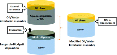
Much recently, the planar interfaces of liquid/liquid (oil/water) and air/water (Langmuir–Blodgett) systems have been applied as templates for two-dimensional assembly of nanomaterials, including GO and GS, and have shown capability of accurate control over the film thickness in the order of nanometers and in-plane packing density.16–27 Normally, in the oil/water system, nanoparticles in aqueous phases were driven to the interface with external assistance, such as sonication, gas bubble and inducing agent, and then self-organized into film.16–20 In air/water system, nanoparticles in volatile oil phase were spread over the water subphase to form floating monolayer, which can be further compressed into compacted feature.21–27 In the present work, we aim to develop a modified oil/water interfacial assembling approach for ultrathin graphene films based on a comprehensive understanding and combination of the above two systems. In our design, the major advantage of the oil/water system (such as simple requirement in equipment, which is mainly a beaker and syringe) and some merits from air/water system (such as the minimum demand on the feeding source) will be integrated into the new developed method. As a key issue, how to appropriately introduce GSs to the oil/water interface will be decisive to the final quality and performance of the products. One initial idea is GSs dispersed in certain solvent being directly injected into the system and simultaneously entrapped at the interface. Hence, the selected solvent needs to play two roles at the same time, namely, (1) good dispersant for GSs or functionalized ones; (2) help with the interfacial accumulation of GSs. The relationship between the proposed strategy and its parental systems is illustrated in Fig. 1a. To the best of our knowledge, there is no report on this kind of method thus far, and none of the well-known dispersants for graphene, such as N-methylpyrrolidone (NMP), N,N′-dimethylformamide (DMF) and dimethyl sulfoxide (DMSO), can be able to fulfill the expected multi-functions.


image file: c4ra05160b-f1.tif
Fig. 1 (a) Design and (b) schematic illustration of the proposed oil/water interface assembly.

More recently, it is reported that inducing agents, specifically ethanol and methanol, can effectively accelerate the collection of GO at either oil/water or air/water interface.23–27 Moreover, according to our latest research, sulphonated graphene could show satisfactory dispersiblity in ethanol due to their modified surface polarity.27,28 Therefore, considering these two facts may offer us a possible solution to the above question. As a proof-of-concept, here we demonstrate a novel self-assembly of graphene film by direct introducing GS/ethanol dispersion at the hexane/water interface (Fig. 1b), and their potential application as transparent conducting electrode and thin film supercapacitor.

2. Experimental section

2.1 Interfacial assembly of graphene monolayer film

Sulphonated GSs were synthesized by a multi-step process as described in previous work.28 To establish the oil/water interface, anhydrous hexane (5–10 ml) was carefully layered on the top of distilled water (40 ml) in a standard 150 ml beaker with a cross-section of ∼32 cm2. Then, GS/ethanol dispersion (∼0.05 mg ml−1) was slowly injected into the water subphase at a maximum speed of 0.2 ml min−1. After stabilizing for 20 min, most of the hexane was carefully drawn away by a syringe, and the rest was left to evaporate. After complete removal of hexane, graphene film in dark-grey color was exposed floating on the subphase. The film was transferred onto different kinds of substrates (including quartz slide, glass and mica) by dipping into and lifting the substrates out of the water slowly (max. 1 mm min−1). All the substrates need to be cleaned with ethanol and acetone repeatedly, and then pre-treated with piranha solution (H2SO4[thin space (1/6-em)]:[thin space (1/6-em)]H2O2 = 4[thin space (1/6-em)]:[thin space (1/6-em)]1) for 30 min to make their surface hydrophilic. The transferred film was blow-dried with nitrogen gas and further dried in a vacuum oven under 60 °C for 30 min to ensure its bonding with the substrate. Multilayered film was fabricated by layer-by-layer by repeating the above mentioned process.

2.2 Characterization

The morphology and microstructure of the films were characterized by CCD optical microscopy, scanning electron microscopy (SEM, Philips XL30) and tapping-mode atomic force microscopy (AFM, SPA-400). The coverage of the films is calculated using software analysis of SEM images based on contrast difference between the substrate, the first layer and the second layer. Optical transmittance of the films was measured on a UV-vis spectrophotometer (Varian, Bio100). Sheet resistivity of the films was measured by a four-probe method. Cyclic voltammetry (CV) and galvanostatic charge/discharge analysis were carried out using a three-electrode cell system (Autolab PGSTAT128N), in which a glassy carbon electrode and a saturated KCl electrode were used as the counter and reference electrodes, respectively, and a 1 M NaCl solution was used as the electrolyte.

3. Results and discussion

The main novelty of the proposed approach lies in the use of ethanol as a dispersant and inducing agent simultaneously for interfacial assembly of GSs. As shown in Fig. 2a, once being released into the water, GS/ethanol dispersion will form upward convection and quickly reach to the interface, and cause short-time disturbance, which can be considered as release of the interfacial tension with the intrusion of GSs. Technically, the dispersibility of graphene in ethanol is relatively poor due to their large difference in surface polarity, which could be improved the by introduction of polar functional groups onto graphene such as, in the current case, the sulphonic group and oxygenated groups.11,28 Moreover, as the inducing agent, ethanol would form hydrogen bonds with the oxygenated groups on the nanosheets and neutralize their surface potential so as to tune their contact angle approaching 90°, which is the most preferable for their interfacial stability.29 After the complete removal of hexane, the fringe of as-obtained film could be seen attaching on the beaker (Fig. 2b). It could also be noticed that the formation of the film is a progressively developing process with continuous feed-in of the GS/ethanol dispersion. At the beginning, GSs were loosely scattered over the interface and self-organized into domain-like patterns without effective interconnection (0.3 ml, Fig. 2c). With more GSs reaching to the interface (0.7 ml, Fig. 2d), these small domains merged into larger ones, and finally, an integrated film with full coverage of the subphase was obtained (1 ml, Fig. 2e).
image file: c4ra05160b-f2.tif
Fig. 2 Photographs showing (a) the upward convection of GS/ethanol dispersion as being released into the hexane/water system, and (b) the fringe of the film attaching on the beaker. (c–e) structural variation of graphene films from disconnected domains to integrated film with the increasing feed-in of GS/ethanol dispersion.

Optical microscopy image in Fig. 3a confirmed the integrity and smoothness of the graphene films collected on quartz substrate, and it is easy to distinguish the film from the substrate (Fig. 3b). Further zooming into the film, a densely packed structure with occasional vacancy was observed and the total coverage of nanosheets on the substrate reaches up to 96.2% (Fig. 3c). Based on the AFM image and corresponding height profile (Fig. 3f and g), the thickness of the film is 1.2–1.5 nm, consistent with that of single-layered sulphonated graphene.11,28 In some area, irregularities, such as folding and wrinkles, could be noticed, which count up to ∼7.8% of total coverage of the monolayer film. To understand the formation of the film, it is necessary to discuss the surface chemistry of the sulphonated GSs, which could be considered as amphiphilic in some sense with most part of the sulphonic acid groups and residual carboxyl groups gathered around the edges, and hydrophobic graphitic basal region.11 According to Pieranski's theory and Young's equation,30–32 the driving force for the self-assembly of nanoparticles at oil/water interface could be attributed to the minimization of total interfacial free energy, in which the particle size and shape are both important for the energy decrease. Particularly, a particle with high aspect ratio will show superior stability to the spherical one at the oil/water interface.33 Bowden et al. have pointed out that menisci-like structures would form around nanoparticles, and attractive lateral capillary force derived from the overlap of such menisci could draw the adjacent blocks closer to maximize their hydrophobic surface area.34 This kind of lateral capillary force is especially significant for particles with high two-dimensional aspect ratio and is sufficient to drive them closely packed. On the other hand, when the nanosheets were forced together in an edge-to-edge manner, the electrostatic repulsion may result in folding, overlapping and wrinkling at the contacted edges and sometimes in the interior regions.24 The second possible reason for these irregularities could be assigned to the highly flexible nature of graphene which will tend to shrink and crumple during the drying process.


image file: c4ra05160b-f3.tif
Fig. 3 Morphological analysis of the graphene films. (a) As-deposited monolayer and two-layer film on quartz substrate. (b and c) Corresponding optical microscopy image and SEM image of monolayer and (d and e) double-layer films. (g and h) AFM image of monolayer on mica substrate and corresponding height profile.

As a key advantage of interfacial assembly, the ability to fabricate multilayer film with a controllable layer number is highly desired for many applications. Because of the hydrophobic nature and poor wettability of graphene, binding agents (usually polymers) were typically necessary in their layer-by-layer process. However, these external impurities may be detrimental to general performance of the resulted films. In our previous research, it has been testified that hydrophilicity of graphene can be remarkably enhanced by controlled sulphonation.27,28 The sulphonated GSs show much better wetting behavior and a lower contact angle with water, making their direct multilayered deposition feasible. As shown in Fig. 3a and d, the second monolayer with coverage of ∼81.7% was successfully deposited over the first one. Moreover, the film surface became rougher after the second deposition, and coverage of the irregular area increased to 16.8% (as shown in Fig. 3e). Similar results have been reported by Huang et al. in their research on multilayer assembly of GO.23–25 Accordingly, when two layers of nanosheets were overlapped in a face-to-face manner, their electrostatic repulsion will result in heavy degree of defects, especially at high packing density, despite the dominant attraction between them. Moreover, due to the soft nature of graphene, roughness in under layer will reflect on and multiply in the upper layer. Experimental parameters, such as the amount of GS, injecting speed of ethanol and the uplifting rate of substrate, are all influential in the structure of final products. Generally, over dosage of the GSs will result in wave-like inhomogeneity and aggregates (as shown in Fig. 4a), and too fast lifting the substrate will bring rupture (as shown in Fig. 4b) into the film.


image file: c4ra05160b-f4.tif
Fig. 4 Effect on the structure of the film from the experimental parameter of (a) 1.5 ml of GS/ethanol dispersion, and (b) lifting the substrate at 2 mm min−1. The rest of the conditions are the same as those described above.

Optoelectronic properties of as-prepared films were discussed to seek their possible application as transparent conducing electrode. As shown in Fig. 5a, the monolayer film showed low absorption over the whole region of visible spectrum and the transmittance at 550 nm reached up to 92.3%, slightly lower than the theoretic value of single-layer graphene (97%). This decrease in transmittance can be mainly assigned to the scattering and absorption of incident light at the defective areas. The characteristic absorption at around 270 nm correspond to π–π* transitions, reflecting the recovery of sp2 bonds. Sheet resistivity of the film is 13.5 kΩ/□ which is much higher than the ITO standard. After the second deposition, the sheet resistivity reduced to 9.6 kΩ/□ with a transmittance of 85.3% (Fig. 5b), which is consistent with the calculated value (86%) when considering the coverage of the second layer. There are two possible reasons for the high sheet resistivity of as-prepared films: (1) the GSs studied in this work is hetero-dispersed with a wide size distribution from hundreds of nanometres to tens of micrometers, and the existence of GSs with small size will undoubtedly result in a large number of sheet-to-sheet junctions and increase the overall resistivity; (2) the introduction of functional groups, specifically sulphonic groups in current case, also bring negative effect on the conductivity of the film. To further improve the optoelectronic properties of current films, additional pre- or post-treatments, such as size fractionation of the GSs, control over the sulphonation degree and chemical doping of resulted films, should be preferable.


image file: c4ra05160b-f5.tif
Fig. 5 Transmittance of (a) single- and (b) double-layered graphene films and their corresponding sheet resistivities.

Other than optoelectronic devices, the graphene-based thin films also show high potential in energy storage systems such as supercapacitors and secondary batteries. In current research, multilayered film with a layer number of 20 (1 × 2 cm2) was fabricated in electrochemical tests. As shown in Fig. 6a, the cyclic voltammetry (CV) results displayed a series of symmetrical curves at different scan rates, indicating that the capacitive process was both reversible and stable. Their nearly rectangular shapes indicate that efficient electrochemical double-layer (EDL) capacitance behavior has been established in the electrode.35,36 Calculated specific capacitance reached up to 292 F g−1 at a scan rate of 2 mV s−1, nearly twice the value of its powder counterpart.28 With the scan rate being increased up to 20 mV s−1, the specific capacitances gradually reduced to 254 F g−1, demonstrating a good rate capability (∼87%) (Figure 6b). Galvanostatic cycling of the electrode was performed with a current density of 100 mA g−1. As shown in Fig. 6c, the charge/discharge curves are almost straight lines, confirming the formation of an efficient EDL and good charge propagation. The calculated specific capacitance (287 F g−1) is consistent with that from CV test. A decrease of only 1.9% on the specific capacitance happened after 50 cycles (Fig. 6d), exhibiting excellent cycle stability and a very high degree of reversibility. To understand the high electrocapacitive performance of the current multilayered film, it is necessary to understand its unique micro-geometry. Different from the randomly oriented stacking as in the powder sample with the wide pore distribution, GSs in current thin film electrode are horizontally arranged with very low degree of aggregates, maximally reserving their surface area. Moreover, the increasing in-plane irregularities, although undesirable for transparent conducting film, could effectively expand the interlayer spacing as pillars and build up interconnected channels for the access of electrolytes. In other words, a self-sustained, three-dimensional hierarchical structure could be established within current ultrathin film. Detailed research on the formation and development of this interior structure with the increase of layer number is ongoing and will be reported later.


image file: c4ra05160b-f6.tif
Fig. 6 (a) Cyclic voltammetry curves of GS multilayer film and (b) corresponding specific capacitance at different scan rates; (c) galvanostatic charge/discharge tests at a current density of 100 mA g−1; (d) variation of the specific capacitance of the film as function of cycle number measured at 5 mV s−1.

4. Conclusion

In this work, ultrathin graphene films were successfully fabricated by a modified oil/water interfacial assembly. Monolayer films with densely packed and highly oriented structure can be obtained by direct injection of a very small amount of GS/ethanol dispersion (1 ml, 0.05 mg ml−1) at the hexane/water interface. Multi-layered film can be readily assembled by simple layer-by-layer deposition without any extra binding materials. The obtained ultrathin films show high potential in application as transparent conducting electrode and thin-film supercapacitors. The transparent conducting electrode based on monolayer film show a high transmittance of 92.3% and a sheet resistance of 13.5 kΩ/□. The specific capacitance of multilayered film reached as high as 292 F g−1, nearly double that of the corresponding powder sample. In addition, the film showed excellent cyclic stability in a long-term charge/discharge test. After 50 cycles, the capacitance decreased by only 1.9%. These encouraging results confirmed our expectation on this new developed interfacial assembly of graphene films, demonstrating a cost-efficient, convenient and controllable approach for ultrathin graphene films with high quality.

Acknowledgements

This work was supported by National Natural Science Foundation of China (21301021, 51303017), Natural Science Foundation of Jiangsu Province (BK20130254), Applied Basic Research Programs of Changzhou City (CJ20135007).

References

  1. K. S. Novoselov, A. K. Geim, S. V. Morozov, D. Jiang, Y. Zhang, S. V. Dubonos, I. V. Grigorieva and A. A. Firsov, Science, 2004, 306, 666–669 CrossRef CAS PubMed.
  2. A. K. Geim and K. S. Novoselov, Nat. Mater., 2007, 6, 183–191 CrossRef CAS PubMed.
  3. C. H. Liu, L. Liu, K. F. Mak, G. W. Flynn and T. F. Heinz, Nature, 2009, 462, 339–341 CrossRef PubMed.
  4. S. J. Guo and S. J. Dong, Chem. Soc. Rev., 2011, 40, 2644–2672 RSC.
  5. X. L. Li, X. R. Wang, L. Zhang, S. W. Lee and H. J. Dai, Science, 2008, 319, 1229–1232 CrossRef CAS PubMed.
  6. M. D. Stoller, S. Park, Y. W. Zhu, J. H. An and R. S. Ruoff, Nano Lett., 2008, 8, 3498–3502 CrossRef CAS PubMed.
  7. G. H. Zeng, Y. B. Xing, J. Gao, Z. Q. Wang and X. Zhang, Langmuir, 2010, 26, 15022–15026 CrossRef CAS PubMed.
  8. S. Bae, H. Kim, Y. Lee, X. F. Xu, J. Park, Y. Zheng, J. Balakrishnan, T. Lei, H. R. Kim, Y. Song, Y. J. Kim, K. S. Kim, B. Ozyilmaz, J. H. Ahn, B. H. Hong and S. Lijima, Nat. Nanotechnol., 2010, 5, 574–578 CrossRef CAS PubMed.
  9. X. S. Li, W. W. Cai, J. An, S. Kim, J. Nah, D. X. Yang, R. Piner, A. Velamakanni, I. Jung, E. Tutuc, S. K. Banerjee, L. Colombo and R. S. Ruoff, Science, 2009, 324, 1312–1314 CrossRef CAS PubMed.
  10. K. V. Emtsev, A. Bostwick, K. Horn, J. Jobst, G. L. Kellogg, L. Ley, J. L. McChesney, T. Ohta, S. A. Reshanov, J. Rohrl, E. Rotenberg, A. K. Schmid, D. Waldmann, H. B. Weber and T. Seyller, Nat. Mater., 2009, 8, 203–207 CrossRef CAS PubMed.
  11. Y. C. Si and E. T. Samulski, Nano Lett., 2008, 8, 1679–1682 CrossRef CAS PubMed.
  12. D. Li, M. B. Muller, S. Gilje, R. B. Kaner and G. G. Wallace, Nat. Nanotechnol., 2008, 3, 101–105 CrossRef CAS PubMed.
  13. Y. W. Zhu, W. W. Cai, R. D. Piner, A. Velamakanni and R. S. Ruoff, Appl. Phys. Lett., 2009, 95, 103–104 Search PubMed.
  14. X. C. Dong, C. Y. Su, W. J. Zhang, J. W. Zhao, Q. D. Ling, W. Huang, P. Chen and L. J. Li, Phys. Chem. Chem. Phys., 2010, 12, 2164–2169 RSC.
  15. M. Yang, Y. Hou and N. A. Kotov, Nanotoday, 2012, 7, 430–447 CrossRef CAS PubMed.
  16. S. Biswas and L. T. Drzal, Nano Lett., 2009, 9, 167–172 CrossRef CAS PubMed.
  17. W. H. Lee, J. Park, Y. Kim, K. S. Kim, B. H. Hong and K. Cho, Adv. Mater., 2011, 23, 3460–3464 CrossRef CAS PubMed.
  18. M. M. Gudarzia and F. Sharif, Soft Matter, 2011, 7, 3432–3440 RSC.
  19. Z. W. Sun, T. Feng and T. P. Russell, Langmuir, 2013, 29, 13407–13413 CrossRef CAS PubMed.
  20. F. Chen, S. B. Liu, J. M. Shen, L. Wei, A. Liu, M. B. Chan-Park and Y. Chen, Langmuir, 2011, 27, 9174–9181 CrossRef CAS PubMed.
  21. S. D. Ren, R. J. Li, X. G. Meng and H. X. Li, J. Mater. Chem., 2012, 22, 6171–6175 RSC.
  22. X. Li, G. Zhang, X. Bai, X. Sun, X. Wang, E. Wang and H. Dai, Nat. Nanotechnol., 2008, 3, 538–542 CrossRef CAS PubMed.
  23. F. Kim, L. J. Cote and J. Huang, Adv. Mater., 2010, 22, 1954–1958 CrossRef CAS PubMed.
  24. L. J. Cote, F. Kim and J. Huang, J. Am. Chem. Soc., 2009, 131, 1043–1049 CrossRef CAS PubMed.
  25. J. Kim, L. J. Coat, F. Kim, W. Yuan, K. R. Shull and J. Huang, J. Am. Chem. Soc., 2010, 132, 8180–8186 CrossRef CAS PubMed.
  26. Q. B. Zheng, W. H. Ip, X. Y. Lin, N. Yousefi, K. K. Yeung, Z. G. Li and J. K. Kim, ACS Nano, 2011, 5, 6039–6051 CrossRef CAS PubMed.
  27. B. P. Jia and L. D. Zou, Chem. Phys. Lett., 2013, 568, 101–105 CrossRef PubMed.
  28. B. P. Jia and L. D. Zou, Carbon, 2012, 50, 2315–2321 CrossRef CAS PubMed.
  29. F. Reincke, S. G. Hickey, W. K. Kegel and D. Vanmaekelbergh, Angew. Chem., Int. Ed., 2004, 43, 458–462 CrossRef CAS PubMed.
  30. P. Pieranski, Phys. Rev. Lett., 1980, 45, 569–572 CrossRef CAS.
  31. B. P. Binks and J. H. Clint, Langmuir, 2002, 18, 1270–1273 CrossRef CAS.
  32. Y. Lin, H. Skaff, T. Emrick, A. D. Dinsmore and T. P. Russell, Science, 2003, 299, 226–229 CrossRef CAS PubMed.
  33. B. P. Binks, Colloidal particle at liquid interfaces, Cambridge Univeristy press, New York, 2001 Search PubMed.
  34. N. Bowden, A. Terfort, J. Carbeck and G. M. Whitesides, Science, 1997, 276, 233–235 CrossRef CAS.
  35. A. V. Murugan, T. Muraliganth and A. Manthiram, Chem. Mater., 2009, 21, 5004–5006 CrossRef CAS.
  36. J. Yan, T. Wei, B. Shao, F. Ma, Z. Fan, M. Zhang, C. Zheng, Y. C. Shang, W. Z. Qian and F. Wei, Carbon, 2010, 48, 1731–1737 CrossRef CAS PubMed.

This journal is © The Royal Society of Chemistry 2014
Click here to see how this site uses Cookies. View our privacy policy here.