
 Open Access Article
 This Open Access Article is licensed under a Creative Commons Attribution-Non Commercial 3.0 Unported Licence
Ruthenium complexes as precursors for chemical vapor-deposition (CVD)
Ruchi
Gaur†
a,
Lallan
Mishra
*a,
M. Aslam
Siddiqi
b and
Burak
Atakan
*b
aDepartment of Chemistry, Faculty of Science, Banaras Hindu University, Varanasi-221005, India. E-mail: lmishrabhu@yahoo.co.in
bThermodynamics, IVG, Faculty of Engineering, and CeNIDE, University of Duisburg Essen, Lotharstr. 1, 47057 Duisburg, Germany. E-mail: aslam.siddiqi@uni-due.de; burak.atakan@uni-due.de
First published on 24th July 2014
Abstract
Ruthenium and its compounds are often used as thin films and can be deposited by chemical vapor deposition. The quality of the films strongly depends on the inorganic precursors, their evaporation behaviour and thermochemistry. This is an area where different aspects of inorganic chemistry and chemical engineering must fit together to provide good thin films. It was noticed that providing firsthand information in one place especially for a learner of this area of research, and collection of reports on different types of ruthenium complexes as CVD precursors would be timely. Thus, in this review a bird's eye view of ruthenium complexes suitable for CVD technology, together with the presentation of different precursors, their synthesis, evaporation, decomposition and film formation is presented. A brief summary of the CVD technique is also presented with future-design, synthesis and usefulness of CVD precursors.
 Ruchi Gaur | Ruchi Gaur received her B.Sc. and M.Sc. degrees from Chhatrapati Shahu Ji Maharaj University, Kanpur India. She obtained her Ph.D. (2012) from Banaras Hindu University, India, under the guidance of Prof. Lallan Mishra. Currently, she is working as a post doctoral fellow at the Indian Institute of Technology, Kanpur, India. Her research focuses on the area of metal based antitumor complexes, coordination-driven self assembly, and metal–organic frameworks. |
 Lallan Mishra | Prof. Lallan Mishra obtained his Ph.D. from D. D. U. Gorakhpur University, India. He did his post-doctoral work at IISc. Bangalore, I.I.T. Kanpur and University of Antwerp, Belgium. He joined the Department of Chemistry, Banaras Hindu University, Varanasi in 1989 and is presently working as Head of the department of BHU. His research interests are in the area of bioinorganic, supramolecular, development of metal based anti cancer drugs and coordination chemistry with the focus on architectural aspects, functional materials. |
 M. Aslam Siddiqi | Dr M. Aslam Siddiqi received his Ph.D. from Lucknow University, Lucknow, India in 1972. Until his retirement in 2013 he was working as a senior scientist at the University of Duisburg-Essen (Germany) at the department of Thermodynamics. His main research fields are the thermodynamic properties of metalorganic compounds, vapor liquid equilibria and the fluid dependence of thermodynamic cycles for energy conversion. |
 Burak Atakan | Prof. Dr Burak Atakan is the chair of thermodynamics in the faculty of engineering at the University of Duisburg-Essen (Germany) since 2002. He received his Ph.D. in physical chemistry at the University of Heidelberg (Germany) in 1992. After working as a scientist at the DLR (German Aerospace Research Center) in Stuttgart until 1995 he continued his research at the University of Bielefeld (Germany), where he obtained his habilitation in physical chemistry in 2000. His research fields are thermodynamic and transport properties of metalorganic compounds, chemical vapor deposition and chemical vapor infiltration of various compounds, energy conversion processes and combustion mechanisms. |
1. Introduction
Over the past few decades, there is a continuous advancement in the design and synthesis of new materials with enhanced functionalities for eventual application in devices for microelectronics and optoelectronics. Despite this progress, it continues to be difficult and challenging among material scientists to design selective and highly efficient new materials for thin film technology especially in microelectronic applications. The unique chemical and physical properties of ruthenium trigger a variety of applications in thin film technology,1 alkane hydrogenolysis,2 surface science,3 hydrogenation reactions,4 and Fischer-Tropsch reactions.5 It is well known that elemental ruthenium is found to be a very promising candidate in thin film technology because of its high work function (4.7 eV), thermal stability even at higher temperature (∼800 °C), low bulk resistivity (7 μΩ cm) and low specific electrical resistivity even in its oxidized state.6 In particular, ruthenium has been shown to force TiO2 films grown on it into the high-k rutile phase, making it attractive for capacitors in microelectronics applications.7 Ruthenium and its conducting thermodynamically stable oxide phase (RuO2) have been used as metallic contact to high dielectric materials such as strontium titanate (SrTiO3), barium strontium titanate [(Ba,Sr)TiO3],8 tantalum pentaoxide (Ta2O5)9 and lead zirconate titanate [Pb(Zr,Ti)O3, PZT]10 and may be used for the preparation of the next-generation gigabit-scale dynamic random access memories (DRAMS).11,12 Ruthenium thin films are also advantageous diffusion barrier as compared to over TaN based on diffusion barriers owing to its low resistivity, chemical stability and low solubility in Cu and thus they become a possible alternative for thin film technology.13 Ruthenium thin films have also been used as seed and barrier layers for copper and silicon deposition due to its high conductivity and chemical inactivity with copper and silicon.14Ruthenium is a promising candidate for developing a deeper understanding of chemical vapor deposition and precursor design for catalytic films due to much individual molecular behavior in surface science and catalysis. In early stage, ruthenium films were prepared by different techniques such as reactive sputtering,15 physical vapor deposition,16 spray pyrolysis,17 pulsed laser deposition (PLD),18 molecular-beam epitaxy (MBE),19 cathodic electrosynthesis20 and by a sol–gel process.21 But these alternative processes create problems such as low conformal coverage, poor crystallinity, high stress levels etc. in the thin films obtained. To overcome these problems the chemical vapor deposition (CVD) method is promising. It often offers excellent coverage, relatively soft conditions, and a compatibility for large scale processing.22 Ruthenium chemical vapor deposition and precursor design is of particular interest because of the outstanding film properties23 such as low resistivity, high thermal stability, good etching ability, good barrier properties against oxygen diffusion, high resistance against capacitor shorting due to the formation of hillocks, severe polarization fatigue and aging and so are useful in electronic applications.24 Ruthenium is also a suitable substrate for growing periodically rippled graphene,25–27 which is attracting great interest for its periodically inhomogeneous electronic properties.28 One of the current frontiers is growing graphene on Ru thin films on sapphire and SiO2,29–31 which is to date problematic for the low crystalline quality of Ru films on insulator substrates. The realization of this goal would allow exotic applications of graphene as a curved mirror for He-atom microscopy32,33 or for graphene/metal contacts in plasmonics.34–36
Accordingly, there is still demand for ruthenium CVD source reagents as found better in view of their advantages such as suitability for scale-up synthetic operation, higher thermal and oxidative stability during storage, higher volatility upon heating, and the capability to induce facile metal deposition under designated CVD conditions. In this account, we have discussed the chemical vapor deposition technology of ruthenium using different Ru containing complexes as precursors. To give a background, a brief summary of the CVD technique and its classifications are also presented with regard to future-design, synthesis and usefulness of CVD precursors.
2. A brief introduction to CVD
Chemical vapor deposition is a technique by which a material is synthesized as a thin film, by the reaction of vapor phase compounds containing the constituents of the film.37 The solids are grown as polycrystalline, epitaxial or amorphous films depending on the materials and reactor conditions. Thus, the occurrence of chemical reactions is an essential characteristic of the CVD method. The kinetics and transport processes depend on surface and gas phase chemical reactions, parameters such as temperature, pressure, input concentration and rate of flow of the reaction are crucial. The CVD process and its reactor are selected by the requirements for substrate material, morphology and coating material, film thickness and uniformity, availability of precursors and cost.38 CVD can be carried out in cold-wall reactors or hot-wall reactors at typical temperature ranging from 200–1600 °C and often at below-atmospheric pressures with and without carrier gases.39 A variety of enhanced CVD processes are established which involve the use of plasma, ions,40 photons (also using lasers) hot filaments, or combustion reactions38 to increase deposition rates and/or lower deposition temperatures. Direct analytical techniques applied to CVD studies are Raman spectroscopy, absorption spectroscopy and gas chromatography.41 Qualitative and quantitative analysis of vapor phase could be carried out by direct attachment of a mass spectrometer to a CVD reactor.42,43The principle of CVD process can be understood stepwise as:
(1) Precursors are transported in the gas phase, gas phase reactions can take place;
(2) Adsorption and transport of the precursors on the surface take place;
(3) Supply of energy (thermal, plasma, light) for breaking the precursor molecules and film formation;
(4) Transport on and desorption of the byproducts from the surface;
(5) Gas phase transport and evacuation of by-products in the gas-phase.44
Most often the reaction conditions are chosen in such a way that surface reaction is rate determining or limiting step, which is at relatively low temperatures or at higher temperatures. Chemical vapor deposition can occur in two different mechanistic ways: either the precursor species polymerize or react in the gas phase forming reactive gaseous species and then adsorb to the surface and form a thin film or the precursor species adsorb first on the surface and react then on the substrate. The first mechanism generally creates poorer coating adhesion compared to the second one.45
Thermodynamics predicts the feasibility of CVD process to occur under certain parameters and it can provide both qualitative and quantitative information about the process. Thus, one of the first steps in considering a CVD process is to perform the thermodynamical calculations to explore the general conditions required for the process to occur. Although, not always data for the free energy of formation of all vapors and condensed constituents of the system are available. Details regarding the thermodynamics of CVD can be found in an interesting review article by Kern and Ban.46,47
Besides thermodynamics, the kinetics of the deposition process is as important. The nature of the rate-controlling step changes with temperature and can often be determined from an Arrhenius plot. It suggests that at lower temperatures the rate-controlling step is some surface process with a constant rate varying with k = Ae−ΔE/RT, A is frequency factor, ΔE is the activation energy-usually varies from 25–100 kcal mol−1 for surface processes. At higher temperatures, the rate-controlling step is generally the transport either by diffusion or convection of the reactants to the reacting surface. The temperature dependence of gas phase diffusion is mild and the deposition-rate follows a less steep slope. At even higher temperatures the precursor may react to particles and a decrease in growth rate at very high temperatures is observed.48 For example, a steep dependence of the deposition rate is observed at lower temperatures where as a milder dependence is observed at higher temperatures in deposition of Si from various sources.49 The deposition-rate can also depend on the crystallographic orientation of the substrate as the deposition rate of GaAs is three to four times faster on the (111) surface of the substrate as compared to growth on the (100) surface.50 The effect of dopants on the semiconductor growth rate and existence of meta-stable phases could also be considered as kinetic effects.51
The substrate temperature, pressure and reaction gas flow rates determine the film formation mechanism and this may help to improve the knowledge about the rate limiting factor which controls the nucleation or growth rate (kinetics). In the context of the present topic, Ru shall be regarded: Substrates like SiO2/Si were used mainly for pure Ru films deposition because of slow deposition rates on other substrates.52
Hones et al. established the growth kinetic of thin ruthenium oxide films from [Ru(tfa)3] in a mixture of oxygen and water which follows a unimolecular reaction of the Langmuir–Hinshelwood-type. The reaction pathways of precursor molecule fragmentation is depicted in Fig. 1.53 From the growth kinetics of [Ru(tfa)3], it is concluded that
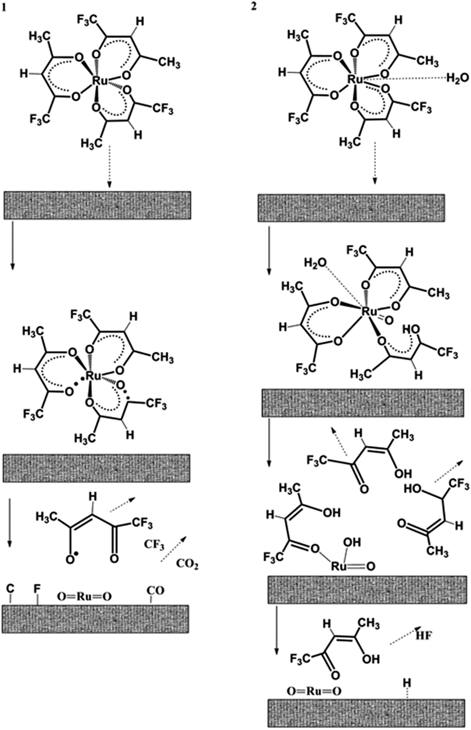 | ||
| Fig. 1 Reaction mechanism of the [Ru(tfa)3] precursor molecule at the substrate surface. (1) Thermolysis with formation of highly reactive radicals, without water. (2) Volatile reaction by-products formation by protonation of the ligands in the presence of water. Adapted from ref. 53. | ||
(1) [Ru(tfa)3] provides most of the oxygen in the RuO2 film and the reaction is unimolecular.
(2) The growth rate varies exponentially with the temperature of the substrate. However, the growth rate of the film increases with the lowering of the partial pressure and it gets saturated at high partial pressures. This behaviour indicates that the reaction kinetics follows a Langmuir adsorption isotherm.
(3) For the deposition of ruthenium thin films, water vapor is required, because water molecules destabilize the precursor complex by partial protonation of the ligands.
As some substrates cannot withstand high temperatures, the use of a plasma or laser light may be a way to start chemical reactions at moderate temperatures. Also, CVD can be performed at different pressures. Many of these CVD variations were named separately as atmospheric pressure CVD (APCVD)54 or low pressure CVD (LPCVD).55 Similarly ultrahigh vacuum CVD (UHVCVD)56 is sometimes used, then the process takes place below ∼10−8 mbar. Whereas, according to the activation used (by either thermally or plasma, laser light or hot wires or flames or others.),57,58 the processes are named as (c) plasma-enhanced CVD (PECVD) and (d) remote plasma-enhanced CVD (RPECVD) as well as (e) microwave plasma assisted CVD (MPCVD) (f) flame enhanced CVD.59 Alternatively, some further CVD processes are named such as (g) atomic layer CVD in which successive layer of different substances deposits and produce the layered crystalline film, (h) combustion CVD is mainly for nanomaterials and based on flame-based technique (i) metal–organic CVD (MOCVD) is the interesting class to deposit the thin films of metal or their oxides, the present review will mainly focus on the latter. Several other classes of CVD processes are described in the literature.45,60
The most common use of CVD is the manufacturing of conformal thin films. A variety of applications for such films play a crucial role in the production of integrated circuits (ICs),61 photovoltaic devices,62 high temperature resistant, corrosion-resistant and wear-resistant protective coatings63 and formation of optical fibers,64 synthetic diamond etc.37 CVD is also used in the fabricating of optical storage media and is suitable for manufacturing semiconductor devices.65 These materials together with some optoelectronic materials like solid state diode lasers have revolutionized the communication technology and are obtained using CVD technique.
In this context, it is of worth to mention that even the optical component of the communications network, the fiberoptic cables are manufactured by CVD in order to achieve the desired refractive index profile.66 The highly bright blue and green light emitting devices (LEDs) based on group-III nitride alloys, like InGaN, are grown on sapphire substrates also formed by CVD technology.67 CVD plays a crucial role in the production of micro electro-mechanical structures (MEMS) which is mainly derived from the silicon microelectronics technology. Most MEMS devices are fabricated from polycrystalline silicon (polysilicon) films deposited on silicon wafers, with intermediate sacrificial SiO2 layers that are later removed by chemical etching.68
Most of the properties, like magnetic, optical and electrical properties of a particular composition of a CVD film depends on its structure. Therefore, factors controlling the structure are of importance. Nucleation and formation of polycrystalline, amorphous and epitaxial CVD films is briefly discussed here. Older concepts of nucleation are based on a thermodynamical approach whereas newer concept of atomistic nucleation are based on statistical mechanics taking into account the chemical bonding characteristics of the solid surface. Different solid surfaces do not have equal bonding characteristics. Those with stronger bonding characteristics favour nucleation.69 The growing nuclei then come into contact and finally coalesce, forming a continuous film. After reaching a certain size, nuclei become energetically more favourable and growth dominates re-evaporation.70
Regular, oriented growth of a polycrystalline substance on another one, is called epitaxy. Epitaxial growth is often a desirable feature in CVD films, mainly in microelectronics, as such films are found superior with regard to their very well ordered and smooth surfaces compared to both, polycrystalline and amorphous films, respectively.71 However, for many applications, polycrystalline or amorphous films are sufficient. These structural forms are more common in CVD as epitaxial films can only be obtained under specific condition like good lattice match between film and substrate, in a certain temperature range and at proper reactant concentrations. In the absence of these conditions, polycrystalline or amorphous modifications of the same material are obtained. The CVD technique has also been found useful in making films of insulating and semiconducting materials which have a wide range of applications specially in modern microelectronic technology and protective coating for high-temperature materials. However, most of the metal films including ruthenium follow a 3D, Vollmer–Weber growth mechanism owing to their high surface energy; this leads to the growth of polycrystalline, columnar films by CVD.72–74
3. Desirable properties of CVD precursors
Primarily, thin film formation by CVD requires that the precursor should be highly volatile,75 soluble in inert solvents if spray evaporation is intended, as inert solvents prevent their own reactions with the precursors and they should be thermally stable at vaporization temperatures, so that no decomposition occurs during vaporization. Furthermore, they should have a preferential reactivity towards the substrate and the growing film. Other factors which determine the structure of the deposited film, are the ratio of deposition rate to surface diffusion rate (time available for surface processes) and the ratio of power density to deposition rate.76,77 The exposed precursor surface area is another important factor which irrespective of the volume (if other factors are constant) determines the rate of vaporisation. The deposition of clean thin films, depends on the decomposition mechanism of the precursor, the temperature regime, but also upon the carrier gas used in the reactor.78 With respect to ruthenium it is found that CVD experiments conducted under high O2 concentrations lead to the formation of rutile phase RuO2 through in situ metal oxidation.79,80 It is also believed that higher oxidation states may have a higher activation energy barrier which may induce hindrance for metal reduction in situ and its deposition. This can also account for the greater stability of the source precursor.78 Under inert gas flow the mass loss of the precursor out of a crucible with time is nearly linear (for the exact theory, see ref. 81) and the residual mass should be negligible.81Since, the volatility is a key property of a CVD precursor it is interesting to enumerate the factors which decrease the vapor pressure in a series of comparable compounds, in order to get an idea of how good (or unsuitable) precursors may look like. Charged or highly polar species are in general non volatile. Adduct formation, polymerization and H-bonding also tend to reduce volatility. Thus, for maximum volatility, molecule must be designed so that steric and inductive effects minimize its tendency of adduct or polymer formation. In this context, metal complexes containing β-diketones are usually found to be volatile. Substitution of H by F is found to increase the volatility of the corresponding complexes further. The increase in volatility of fluorine containing β-diketonates corresponds directly to the extent of fluorine substitution. This owes to increased electronegativity of fluorine atoms as dominating the outer periphery of the complex. The fluorocarbon shell then reduces the van der Waals forces and intermolecular hydrogen bonding between fluorine substituted β-diketonates. For example, introduction of CF3 groups into the pyrazole moiety increases the volatility of bridged ruthenium complexes as compared to nonfluorinated analogues. This is due to the repulsive force between lone electron pairs of the fluorine atoms and the low polarizability of the C–F bonds.82,83 A detailed account of the effect of the nature of metal ions and ligand frameworks on the volatility of metal β-diketonates had already been presented in earlier review.84,85
4. Different classes of ruthenium complexes used as CVD precursors
Since precursors are so important in CVD, we would like to go through the different classes of ruthenium precursors aiming to summarize the state of the art and in order to identify potentials for design and development of precursors. Often precursors are synthesized to be applied in microelectronics and optoelectronics aiming to reduce the thermal budget of film formation. The ruthenium precursors stem either from the available classes of metal complexes or they are even specially engineered compounds. In the deposition process, the Ru-adsorbate bonds play an important role. Initially, CVD precursors included only metallic ruthenium as well as ruthenium dioxide RuO2.86 High quality RuO2 thin film can be obtained by a simple decomposition approach of the volatile precursor RuO4 at 150–220 °C on either glass or silicon substrates RuO4 → RuO2 + O2 by low-temperature chemical vapor deposition; the films are found to be free of carbon impurities, which is not surprising regarding the carbon free precursors.Later on, Sankar et al. prepared crystalline thin film of ruthenium and RuO2 on polyurethane or poly(methyl methacrylate) polymers. Amorphous thin films were deposited on polystyrene or poly(ether/ester)polyurethane block copolymers from volatile RuO4 in presence of H2 carrier gas.24 They choose RuO4 as precursor owing to well established fixative stain of saturated/unsaturated polymers by TEM studies. It developed a direct reaction with unsaturated sites n or with C–H bonds on the polymers with reduction of ruthenium. The films were characterized by different techniques such as Auger, XPS, XANES, XRD and SEM. However recently a large number of ruthenium complexes like ruthenium alkoxides, ruthenium alkyls, ruthenium amidinates, ruthenium diketonates, ruthenium carbonyls and others were exploited as precursor complexes.1,53,81–84 Thus, it is interesting to classify such complexes in terms of the nature of bonding of organic ligands formed by ruthenium and is described as follows:
(a) Ruthenium carbonyls, diketonates and their derivatives
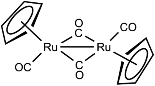
Before the development of metal–organic precursors, ruthenium pentacarbonyl [Ru(CO)5] 1 and triruthenium dodecacarbonyl [Ru3(CO)12] 2 were exploited as CVD precursors.87 The molecular structures of some important ruthenium carbonyls are depicted in Fig. 2. Generally, mononuclear ruthenium carbonyls like ruthenium pentacarbonyl, Ru(CO)5 with a vapor pressure of 50 mm Hg at 18 °C starts to decompose at −18 °C. This characteristic was used by Berry et al.88 and was successfully exploited to grow thin films by using ruthenium pentacarbonyl [Ru(CO)5]. The compound showed limited commercial use as CVD precursor due to its low stability. The decomposition of Ru(CO)2Cl2 or Ru(CO)Br in the absence of air at 200 °C leads to the formation of bright metallic ruthenium films. However, ruthenium thin films were also prepared by annealing of Ru(CO)2Br (boiling point 118 °C, subl. m. p. 140 °C) or Ru(CO)3I (boiling point 114 °C, subl. m.p. 120 °C) in a stream of oxygen and phosgene. A pure ruthenium film was also prepared at 595 °C in a hydrogen atmosphere.89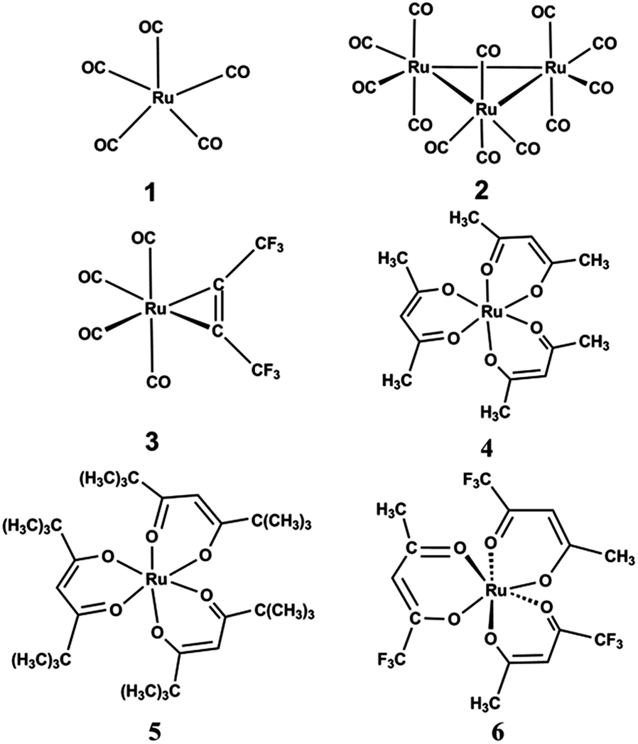 | ||
| Fig. 2 Structures of ruthenium carbonyl derivatives. | ||
In 2004, Wang et al. reported pure and uniform Ru films on Ta and low-resistivity films on SiO2, they were grown by thermal CVD at temperatures as low as 423 K (150 °C) using Ru3(CO)122 without accompanying reactive gas.90 Senzaki et al.91 reported a monometallic alkyne carbonyl ruthenium complex [Ru(hfb)(CO)4] 3, where hfb = hexafluoro-2-butyne which produced a film of 1800 Å thickness in 3 min without any carrier gas at 500 °C.
The second category of ruthenium precursor complexes are ruthenium-β-diketonates or Ru(CO)2(β-diketonates)2.92 Simple complexes of type [Ru(acac)3] 4, acac = acetylacetonatemonoanion (brown colour) were prepared by Wolf et al.93 A modified procedure by Rose et al. was also exploited to prepare ruthenium complexes.94 Its thermal properties for the preparation of RuO2 films by CVD was studied by Bykov et al.95 (see also Table 1) The complex and its trifluorinated derivative were found as prospective precursors in CVD for the preparation of RuO2 and Ru films.96 The parent complex [Ru(acac)3] follows similar decomposition pathway in both a nitrogen and a hydrogen containing atmosphere in TG measurements.97 Both the complexes melted at 232 and 216 °C, respectively with a corresponding sublimation yield of 65.00 and 100.00%. The thermodynamic properties of several β-diketone complexes have been widely covered in the literature.98
| Compound | Process | Number of points | T/°C | ΔHoT kJ mol−1 | ΔSoT kJ (mol K)−1 |
|---|---|---|---|---|---|
| Flow method | |||||
| [Ru(acac)3] | Subl. | 7 | 150–220 | 127.0 ± 0.9 | 212.5 ± 2.0 |
| Silica-membrane zero gauge | |||||
| [Ru(tfa)3] | Subl. | 13 | 110–150 | 90.0 ± 3.0 | 163.2 ± 7.2 |
| [Ru(tfa)3] | Vapor | 11 | 160–210 | 78.7 ± 0.8 | 137.2 ± 1.7 |
Green et al. also reported that ruthenium acetylacetonate resulted in the deposition of RuO2, only at elevated temperatures of 873 K. These films proved to have excellent conformation, which is one of the main advantages of the CVD process.99 Conducting thin films of RuO2 were grown on glass by metal–organic chemical vapor deposition (MOCVD) at lower substrate temperatures i.e. 623 K from tris-trifluoroacetylacetonate-rutheniumIII [Ru(tfa)3] 6 tri substituted fluoro derivative of acetyl acetonate.100
The study thus, indicated that [Ru(tfa)3] is a good CVD precursor due to its high volatility and high thermal stability in both vacuum and in the presence of O2. Additionally, there are no transport problems of the compound to the substrate. The acceptable temperature regime for the deposition of RuO2 film by both precursors [Ru(acac)3] and [Ru(tfa)3] is 300 °C or higher. A mixture of oxygen and water as carrier gas improved several thin film properties like resistivity. The thin film growth mechanism was studied by in situ ellipsometry53 which showed that the nucleation occurred with lateral and vertical island growth in a first step followed by a homogeneous film growth preserving the surface roughness. A model reaction mechanism is proposed for growth kinetics: The reaction kinetics follows a first-order Langmuir–Hinshelwood mechanism with growth rate dependent deposition parameters.101 The film properties such as conductivity and adhesion were improved in the presence of water vapor due to a destabilization of the precursor complex which catalyzes the fragmentation at the hot surface and stabilizes the volatile ligand.
Vasilyev et al. reported surface selective growth of ruthenium films from tricarbonyl(η4-cyclohexa-1,3-diene)ruthenium 7 under low-temperature pulsed CVD conditions in the temperature range of 110–275 °C as shown in Fig. 3.102 A year later, the Vasilyev group further investigated the resistivity and surface morphology of Ru films grown on sub-nanometer-thick Pt–Pd alloy seed layers in a surface selective growth region at 110–185 °C using tricarbonyl{η4-cyclohexa-1,3-diene}ruthenium, ammonia, nitrous oxide, hydrogen, and pulsed chemical vapor deposition conditions.103 The grown film morphology was stable up to 400–600 °C even after rapid thermal processing but revealed surface agglomeration at 700 °C. Vasilyev104 further studied the nucleation and initial stages of the growth of ruthenium layers on different surfaces in the temperature range 110–350 °C under the pulsed deposition from vapor phase with participation of a carbonyl–diene precursor [Ru(CO)3C6H8] in the presence of NH3, N2O and H2 as the second reagent. The growth of the ruthenium layers, formation of nuclei (nucleation) proceeds via a complex multifactor process which depends on the parameters of the deposition process, its type, properties and the uniformity of the sample surface. The Ru nucleation was determined at a stage of growth of the layers and is improved depending on the surface type at a low deposition temperature. It follows the order: Si3N4 ≤ SiO2; Si < Al2O3; HfO2 ≤ Pt–Pd; Pt; Ru.
 | ||
| Fig. 3 Molecular structure of tricarbonyl(η4-cyclohexa-1,3-diene)ruthenium and [Ru(tmhd)3]. | ||
In 2001, Lee et al. explored pure and highly conducting RuO2 thin films with good electrical resistivity as low as 45 μΩ cm using tris(2,2,6,6-tetramethyl-3,5-heptanedionato)ruthenium [Ru(tmhd)3] 8 as depicted in Fig. 6. The films were deposited only on Si substrates at 250–450 °C by low pressure metal organic chemical vapor deposition (LPMOCVD).105 It is observed that [Ru(tmhd)3] is a very promising CVD precursor due to its high vapor pressure and low decomposition temperature. As [Ru(tmhd)3] is a solid substance, its direct delivery in the reactor creates some problem. So, Direct liquid injection (DLI) systems were used with a flash evaporator by dissolving [Ru(tmhd)3] in n-butylacetate.23 The ruthenium and ruthenium oxide thin films were deposited in a temperature range of 250–450 °C. The formation of pure ruthenium thin films was preferred at low O2 flow rate (300 sccm) and high injection rate (0.07 mL min−1) of the precursor solution over 350 °C. However RuO2 films with low resistivity (approximately 45–60 μΩ) were deposited at lower injection rate having dense and smooth surface morphology. Bai et al. also reported a highly conductive RuO2 thin films with either (110)- or (101)-textured orientations grown by metal–organic chemical vapor deposition (MOCVD) on both SiO2/Si(001) and Pt/Ti/SiO2/Si(001) substrates from Ru(tmhd)3 at low temperature ranges from 275 °C to 425 °C.106
Lee et al. again extended the work by developing and characterizing air stable ruthenium CVD precursors such as [Ru(CO)2(hfac)2] 9 and [Ru(CO)2(tmhd)2] 10 (hfac = 1,1,1,5,5,5-hexafluoro-2,4-pentanedione or hexafluoro acetyl acetonate, tmhd = tris(2,2,6,6-tetramethyl-3,5-heptanedionato)) which showed deposition of pure Ru films with small amounts of impurities in the presence of carrier gases such as H2 and Ar.107 Based on the isolation and characterization of the volatile co-products, they proposed the possible mechanism for Ru deposition. The only free ligand (tmhd)H and metallic Ru was obtained using [Ru(CO)2(tmhd)2] 10 as the source reagent in H2 as the carrier gas. However in the case of [Ru(CO)2(hfac)2] 9, free ligand (hfac)H together with a dark red Ru(III) complex, [Ru(hfac)3] (25 ± 41%) were obtained. The outline of the deposition pathway is depicted in Scheme 1.
 | ||
| Scheme 1 Mechanism for the formation of ruthenium thin film from [Ru(CO)2(hfac)2] and [Ru(CO)2(tmhd)2]. Adapted from ref. 91. | ||
Further, Lai et al.108 synthesized diketonate complexes of ruthenium such as [Ru(CO)2(hfac)2] 9, [Ru(CO)2(tmhd)2] 10, [Ru(CO)2(acac)2] 11 and [Ru(CO)2(tfac)2] 12 in high yields by the reaction of Ru3(CO)12 with substituted β-diketone ligands such as (hfac)H, (tmhd)H, (acac)H and (tfac)H at 160–170 °C in hydrocarbon solvents (pentane or hexane) as depicted in Scheme 3. One isomer of the tfac complex (12a) was also isolated during the reaction revealing octahedral coordination geometry with two CO ligands located at cis-positions and with CF3 groups of β-diketonate ligands trans to the CO ligands which was identified by a single crystal X-ray diffraction study. Thermogravimetric analysis (TGA) showed that complex 9 is more volatile than its parent acac complex 11 owing to the CF3 group reducing the intermolecular attraction. Whereas, complex 10 exhibited a lower volatility than complex 12 due to the smaller molecular weight which results in weaker van der Waals attractive interactions between each of the individual molecules. The deposition of ruthenium thin film was observed at temperatures of 350–450 °C under H2 atmosphere or at temperatures of 275 °C-400 °C using a 2% mixture of O2 in argon as carrier gas from complexes 9 and 10. Under 100% O2 atmosphere, conductive RuO2 thin films were deposited at a preferred (200) orientation at 350 °C with the lowest resistivity (156 μΩ cm) obtained using complex 9. The controlled partial pressure of oxygen (i.e. 2%) and accurate tuning of the deposition temperature are important for the formation of pure thin films i.e. a higher partial pressure of O2 and higher temperatures would result in a mixture of Ru and RuO2 thin films. The synthetic strategy and molecular structures of some dicarbonyl β–diketonato ruthenium derivatives are shown in Fig. 4(A) and (B), respectively. Details of the different CVD parameters observed for these complexes under different conditions are summarized in Table 2.
 | ||
| Fig. 4 (A) Schematic illustration of reaction of metal carbonyl with diketones (B) Some dicarbonyl β-diketonato ruthenium derivatives. Adapted from ref. 108. | ||
| Entry | Source | CGFR/sccm | T s/°C | T D/°C | P s/Torr | Thickness/Å | D rate/Å min−1 | Resistivity ρ/μΩ cm |
|---|---|---|---|---|---|---|---|---|
| a CGFR: carrier gas flow rate, Ts: source temperature, TD: deposition temperature, Ps: initial system pressure, D rate: deposition rate. and Cont.: content of nonmetal elements determined by XPS. | ||||||||
| 1 | 9 | H2 (20) | 28 | 350 | 5 | 1600 | 23 | 618 |
| 2 | 9 | H2 (20) | 28 | 400 | 5 | 3200 | 46 | 39 |
| 3 | 9 | H2 (20) | 28 | 450 | 5 | 4800 | 69 | 26 |
| 4 | 9 | O2 (2%)/Ar (10) | 50 | 300 | 5 | 600 | 12 | 34 |
| 5 | 9 | O2 (2%)/Ar (10) | 50 | 350 | 5 | 1450 | 28 | 15 |
| 6 | 9 | O2 (2%)/Ar (10) | 50 | 400 | 5 | 5000 | 96 | 37 |
| 7 | 10 | O2 (2%)/Ar (10) | 80 | 275 | 1 | 1400 | 31 | 206 |
| 8 | 10 | O2 (2%)/Ar (10) | 80 | 325 | 1 | 1600 | 36 | 111 |
| 9 | 10 | O2 (2%)/Ar (10) | 80 | 375 | 1 | 3000 | 67 | 24 |
| 10 | 9 | O2 (10) | 25 | 300 | 5 | 1600 | 80 | 218 |
| 11 | 9 | O2 (10) | 25 | 350 | 5 | 4800 | 240 | 156 |
| 12 | 9 | O2 (10) | 25 | 400 | 5 | 5400 | 270 | 170 |
Cheng et al.109 investigated the initial growth behavior of ruthenium (Ru) on Si (100) surfaces from (Ru(hfac)2(CO)2) in a temperature range of 548 ≤ T ≤ 623 K using atomic force microscopy and X-ray photoelectron spectroscopy. The Volmer–Weber growth110 dominates the initial stage of the deposition for the growing sample and the nucleation rate increases with increasing substrate surface termination sites. They also studied the kinetic behaviour of the nuclei formation process, which showed a lower activation energy on H-terminated surface (5 kcal mol−1) than on the oxide surface (11 kcal mol−1). The reaction kinetics suggest that the deposition is controlled by hfac dissociation step due to high dissociation energy for Ru-hfac (241 kcal mol−1) compared to Ru–CO (57 kcal mol−1). Based on the experimental results together with theoretical calculations of the precursor formation energies, they proposed the following surface chemistry mechanism depicted in Fig. 5.
 | ||
| Fig. 5 Reaction mechanism proposed for [Ru(hafc)2(CO)2] on both (a) H-terminated and (b) OH-terminated Si(100) surfaces. Adapted from ref. 109. | ||
Similar studies were also carried out for other ruthenium substituted carbonyls complexes by Lai et al.111 They reported a new class of (amak)H ligands that is fluoro alcohol molecules with pendant amine functional group similar to the structure of β-diketonate ligand (hfac)H as depicted in Fig. 6.
 | ||
| Fig. 6 Structure of (amak)H ligand similar to (hfac)H ligand adapted from ref. 109. | ||
Mostly, the (amak)H ligand having an amino group and an ionized alkoxy group, reacts with the cationic metal centre and forms stable five membered metallacycle arrangements.112 The (amak)H ligands possess two electron-withdrawing CF3 groups and enhance the acidity (pKa = 5.35–6.39),113 reactivity and volatility in comparison to amino acids. So the (amak)H ligand is very suitable for the preparation of volatile metal chelate complexes for MOCVD applications. They (Lai et al.)108 reported a series of ruthenium complexes [Ru(CO)2(amak)2] (R = 13: H, 14: Me) and [Ru-(COD)(amak)2] where COD = 1,4-cyclooctadiene and R = 15: H, 16: Et, 17: (CH2)2OMe)) by the direct reaction of fluorinated amino alkoxide (amak)H with [Ru3(CO)12] and [Ru(COD)Cl2]x respectively as depicted in Scheme 2.
 | ||
| Scheme 2 Synthetic scheme for the preparation of [Ru(CO)2(amak)2] and [Ru-(COD)(amak)2] complex. Adopted from ref. 112. | ||
A single crystal X-ray diffraction study112 showed that the carbonyl derivative of ruthenium complexes (such as 13, 14) exhibit only one type of structure with cis carbonyl ligands and with oxygen atoms of chelating amino alkoxides located trans to the carbonyl ligands. Whereas, the COD based ruthenium complexes show two distorted skeletal arrangements: one with cis amine functional groups (complex 15), while the second has trans amino groups and with alkoxide oxygen atoms located at cis to COD ligand (complex 16, 17), as shown in Fig. 7.
 | ||
| Fig. 7 Structure of [Ru(CO)2(amak)2] and [Ru-(COD)(amak)2] complexes. Adapted from ref. 112. | ||
These complexes showed very good thermal stability and volatility.112 Only complexes 13 and 16 were selected for CVD studies because of their higher volatility and lower melting point.112 The deposition took place at temperatures of 325–425 °C in the presence of both H2 and a mixture of 2% O2 in argon as carrier gas. Complex 13 deposited lustrous, silver-gray colored thin films which adhered very well to the substrate surface at 375 °C using H2 as carrier gas. Hexagonal C-axis oriented Ru thin films with (001) preferential orientation were deposited on glass substrates in a mixture of argon and ambient O2. By switching to the COD complex 16, Ru thin film with dense and smooth surface morphology can be obtained at a temperature as low as 325 °C under the mixed carrier gas.
(b) Organometallic ruthenium derivatives
Organometallic compounds of ruthenium with especially hydrocarbyl containing like alkyl, allyl, olefin or cyclopentadienyl groups were found to be suitable precursors in chemical vapor depoisition.114 The presence of hydrocarbyl precursors facilitate the thermal and/or photolytic decomposition to provide bare metal atoms condensing to form thin films of especially of nanoparticle size which are often also free from any contamination.115 In this process, the Ru-adsorbate bond plays an important role in thin film formation.In this class of ruthenium compounds, several compounds based on cyclopentadienyl ligands have been prepared and studied as CVD precursor.116–127 The ligands attached to Ru(0) are shown in Fig. 8.
 | ||
| Fig. 8 The structure of some ruthenium cyclopentadienyl compounds. | ||
Ruthenocenes 17 are widely applied in the preparation of resistors; they are also used as additives to liquid crystals and for plating of multilayer electrodes with oxides and metals. The plasma induced vapor phase decomposition of ruthenocenes was used to produce metallic films at sufficiently high rate.116,117 Ruthenocene (rutheniumdicyclopentadienyl) was first synthesized in 1952 by Geoffrey Wilkinson, a Nobel laureate who assigned the structure of ferrocene only a year earlier. Originally, ruthenocene was prepared by the reaction of ruthenium tris-acetonate with excess of cyclopentadienyl magnesium bromide.118–120 Ruthenocene may also be prepared by the reaction of the sodium salt of cyclopentadiene with ruthenium dichloride as depicted in following Scheme 3.
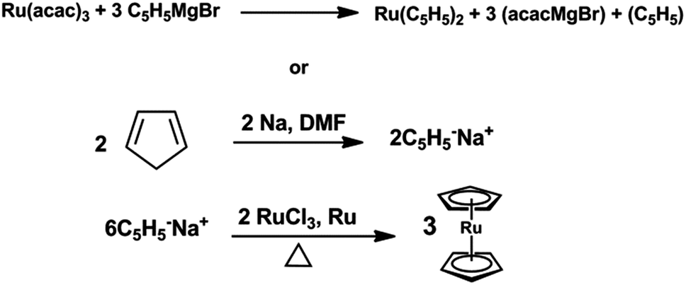 | ||
| Scheme 3 Preparation methods of ruthenocene. | ||
Aoyama et al. reported polycrystalline columnar ruthenium films deposited by liquid source chemical vapor deposition using ethylcyclopentadienyl)ruthenium [Ru(C2H5C5H4)2] as precursor yielding films with low resistivity, small tensile stress, and excellent step coverage.121 The complex [Ru(C2H5C5H4)2] allows a repeatable and reproducible delivery in vapor form into the CVD reactor and is found very useful in the production of capacitor electrodes [(ethylcyclopentadienyl)ruthenium(II)] 17a122,123 have been fairly explored as CVD precursors. Although this precursor can be used to produce pure films of low resistivity when reacted with oxygen however the growth rates are very low or not reported.116 Therefore, another group of scientists including Nabatame et al. explored liquid source chemical vapor deposition from bis-(ethylcyclopentadienyl)ruthenium dissolved in THF and obtained pure ruthenium thin films deposited on SiO2/Si substrates.124 Later on, Kim et al.125 also reported [Ru(EtCp)2] 17a as precursor for Ru and RuO2 composite films grown on TiN/Ti/Si substrate by MOCVD. They investigated iodine sources (CH3I, C2H5I) for improving the smoothness of the film surface at 300 °C for its application as a bottom electrode of a high density DRAM capacitor and reduce the leakage characteristics of Ru electrodes. As iodine containing sources were introduced during the deposition, a dramatically enhanced nucleation of thin film was observed at the initial deposition stage and the surface roughness of the films was reduced considerably without affecting crystallinity or the deposition rate of the composite films.
Further in 2006, Hur'yeva et al. explored pure ruthenium thin films by liquid-delivery metal–organic (MO)CVD in toluene in the temperature range of 330–460 °C via an oxygen-assisted pyrolysis.44 The deposition of ruthenium thin films was controlled by surface reaction kinetics as the rate-limiting step (with an activation energy of 1.4 eV that is 135.1 kJ mol−1) below 400 °C.
Ru thin films grown by [Ru(EtCp)2] showed good properties such as low electrical resistivity, high deposition rates, and low impurity concentrations; however, [Ru(EtCp)2] is very expensive and thus not suited for CVD in a mass production stage. Therefore, there is still a need of new precursors that can have a comparable performance as required. One high-growth rate precursor developed, is cyclopentadienyl-propylcyclopentadien ruthenium(II) [RuCp(i-PrCp)] 18.126 A [RuCp(i-PrCp)] complex leads to single phase metallic ruthenium films under all deposition conditions with growth rates of 7.5 nm min−1 to 20 nm min−1 also with a low resistivity (12 μΩ cm) at the Ru/TiN interface. The interface between Ru and TiN was not changed even after annealing at 600 °C under a N2 atmosphere because of negligible amount of residual oxygen content. However, films showed a poor nucleation behaviour both on SiO2 surfaces as well as on Ta2O5 surfaces owing to the non wetting behaviour of Ru on SiO2 resulting in a rough surface morphology or very small film thicknesses respectively. The decrease in film growth rate indicated an increased stress which also affected the nucleation behaviour through intrinsic stress generation by zipping of the nuclei. This phenomenon was explained by a diffusive stress relaxation mechanism.127
Complex 17 was used in preparation of complex 26–28 in 7, 14, 23 and 73% yield respectively as shown in Scheme 4. On prima facie, one can understand that complexes 23 and 24 lead to self assembled structure (bimolecular or more), because they contain carboxyl groups. However, to understand the quantitative differences in the reactivity of such ruthenocenes at least a theoretical investigation is required by optimizing the structures and calculating the electron density on each molecule. The physical properties of such molecules reported by Siddiqi et al.128 could be taken into consideration to correlate their physical properties with the localization of electron density on ruthenium atom or on the molecular skeleton as a whole. It is concluded that 17–26 are most thermally stable molecule good volatility for CVD application.
 | ||
| Scheme 4 Synthetic strategy followed for the preparation of complexes 23–26. Adapted from ref. 128. | ||
It is well known that introduction of trimethylsilyl groups in ruthenocenes resulted in both high vapor pressures and low melting points.129 Recently, Tuchscherer et al.130 reported synthesis, characterization and application of a series of trimethylsilyl, l-tert-butyl-substituted and half open ruthenocenes as CVD precursors for ruthenium thin film deposition. The complexes were characterized by single crystal X-ray diffraction and their synthetic route is depicted in Scheme 5 and 6. All these ruthenocenes evaporate without decomposition at atmospheric pressure. The highest volatility among all ruthenocenes was found for 31 and 32. It was also observed that the deposition temperature increases with the number of SiMe3 groups. All complexes are found to be good precursors for MOCVD. The ruthenium film depositions on Si/SiO2 targets were carried out in the temperature range of 633–688 K with a flow rate of 50 mL min−1 using nitrogen as the carrier gas. Pure ruthenium thin films were formed from tBu-functionalized ruthenocenes 29 and 31, while mixed ruthenium/SiO2 layers were obtained from 27, 28, 29 and 32. The appropriate layers possess thicknesses between 75–135 nm and are conformal and dense as proven by SEM, EDX spectroscopy, and XPS studies.
 | ||
| Scheme 5 Synthesis protocol for the preparation of ruthenocenes 28 and 30. Adapted from ref. 130. | ||
 | ||
| Scheme 6 Synthesis protocol for the preparation of half open ruthenocenes 31 and 32. Adapted from ref. 130. | ||
Another family of ruthenium CVD precursors includes ruthenium arene–diene compounds of the type [Ru(η6-C6H5R)(η4-diene)] (R = H, Et, etc.; diene = 1,3-butadiene, 1,3-hexadiene, 1,5-cyclooctadiene, etc.) allowing pure Ru deposition at relatively low temperatures. Ruthenium films obtained from (η6-benzene)(η4-1,3-cyclohexadiene) ruthenium precursor complex (see Fig. 9) were deposited on a p-type(100)silicon substrate by MOCVD without any reaction gas.131 The composition of the film was established using the elastic recoil detection time of flight (ERD-TOF) technique132 using both, the flight time and the energy of the recoiled elements.
 | ||
| Fig. 9 Structure of (η6-benzene)(η4-1,3 cyclohexadiene) ruthenium, Ru(C6H6)(C6H8). | ||
Further, Schneider et al.6 had also exploited [(benzene)(1,3-cyclohexadiene)Ru(0)] 33 as a MOCVD precursor for the formation of ruthenium thin films. They investigated mainly the process parameters which promote the purity of the deposited ruthenium films without the help of a reactive gas. The experiments were performed with Si wafers as substrates at a total pressure of 50 mbar, substrate temperature range of 200–450 °C, and helium carrier gas velocity of 1.5 to 16.5 cm s−1. The synthetic strategy for the preparation of [(benzene)(1,3-cyclohexadiene)Ru(0)] is depicted in Scheme 7. Pure ruthenium films (with only 3 mol% carbon impurity) were deposited at a substrate temperature of 300 °C and a carrier gas velocity of 12.8 cm s−1.
 | ||
| Scheme 7 Preparation method some closed and open ruthenocene. | ||
From Fig. 10, it is clearly observed that the formation of benzene by dehydrogenation of 1,3-cyclohexadiene takes place effectively in the surface reaction.6 The hydrogen obtained from the dehydrogenation could be trapped in the ruthenium film and is not removed by the carrier gas even at high flow velocities or high substrate temperatures. However, both ligands are directly connected by hydrogen transfer.
 | ||
| Fig. 10 Gas chromatogram of condensable organic by-products of the MOCVD formation of a thin ruthenium film with [(benzene)(benzene)(1,3-cyclohexadiene)Ru] as the precursor. Source ref. 6. | ||
The formation of benzene from 1,3-cyclohexadiene is thermodynamically strongly favoured due to its low Gibbs energy of formation. From the experimental findings (GC), the reaction mechanism for the formation of ruthenium thin film from [(benzene)(benzene)(1,3-cyclohexadiene)Ru] was proposed6 and summarized in Scheme 8. The authors also established the thermodynamic aspect of the adsorption/desorption equilibrium and calculated the gas phase equilibrium constant, K as given in Table 3 for a total pressure of 50 mbar and at various temperatures.
 | ||
| Scheme 8 Decomposition of [(benzene)(1,3-cyclohexadiene)Ru(0)] and ruthenium surface chemistry of its ligands. Adapted from ref. 6. | ||
| Reaction | Gas Phase equilibrium constant, K (-) | ||
|---|---|---|---|
| C6H8 ↔ C6H6 + H2 | 1.19 × 10⁹ | 5.20 × 10⁸ | 2.41 × 10⁸ |
| C6H8 + H2 ↔ C6H10 | 6260 | 42.7 | 0.30 |
| Temperature, T (°C) | 200 | 300 | 450 |
Recently, Jipa et al. synthesized and characterized some methylated [(arene)(1,3-cyclohexadiene)Ru(0)] complexes such as [(benzene)(2-methyl-1,3-cyclohexadiene)Ru(0)] 35133 as shown in Scheme 7. Scheme 9 shows a possible reaction mechanism which follows the conversion of the 2-Me-1,3-CHD ligand of 35 into toluene without isomerization and reduction by a C–H bond activation of adsorbed Me-CHD.133 The intermolecular hydrogen transfer processes, and the isomerisation of 2-Me-1,3-CHD also takes place, which lead to further Me-CHD isomers without affecting the benzene ligand owing to its high stability.
 | ||
| Scheme 9 MOCVD and follow-up chemistry of the ligands of complex 35 at 200–300 °C substrate temperature. Adapted from ref. 133. | ||
Schneider et al. synthesized a half open ruthenium complex such as [(toluene)(1,5-cyclooctadiene)Ru(0)] 36 and deposited films on copper and silicon substrates in a vertical cold wall reactor. It led to the formation of thin metallic ruthenium films with low carbon content at 150–450 °C.134 Smooth homogeneous ruthenium thin films were obtained using He carrier gas at a pressure of 100 mbar in the temperature range of 160–250 °C. The synthetic path is shown in Scheme 7.
The MOCVD process starting with precursor 36 showed that the decomposition of ligands into toluene and 1,5-COD with traces of the solvent n-hexane were found on the surface.135n-Hexane was used throughout the synthesis of 36 and assumed that it is not a decomposition product of the ligands. The reaction pathways are depicted in Scheme 10.
 | ||
| Scheme 10 Basic CVD Process of 36 and isomerization and dehydrogenation of the dissociated ligands 1,5-COD at the ruthenium surface. Adapted from ref. 135. | ||
Jipa et al. also synthesized some methylated [(benzene)(1,3-butadiene)Ru(0)] derivatives such as [(benzene)(2-methyl-1,3-butadiene) Ru(0)] 37, [(benzene)(2,3-dimethyl-1,3-butadiene) Ru(0)] 39 and [(2,3-dimethyl-1,3-butadiene)(toluene)Ru(0)] 38 as novel MOCVD precursors with favorable deposition properties for thin polycrystalline ruthenium films with a low surface roughness as shown in scheme 7.135 Polycrystalline thin ruthenium films with rough surface were deposited on silicon wafers at 200 and 400 °C substrate temperatures in a nitrogen gas atmosphere. The reaction kinetics starts with the activation of C–H and C–C bonds of hydrocarbons with the complex as a highly active Fischer-Tropsch catalyst and forms thin ruthenium films on the surface as depicted in Scheme 11.
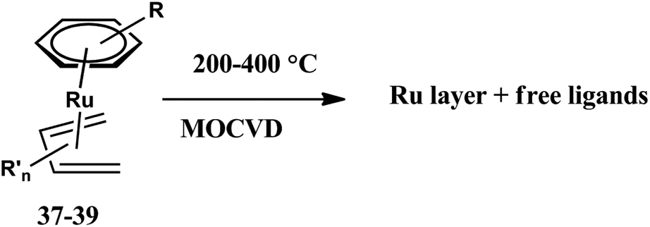 | ||
| Scheme 11 Ru layer formation from complexes 37–39. Adapted from ref. 127. | ||
Among the different sources of ruthenium mentioned above, [Ru(DMPD)(EtCp)], (DMPD = 2,4-dimethylpentadienyl, EtCp = ethylcyclopentadienyl) showed the best physical properties which makes it a promising precursor of MOCVD as depicted in Fig. 11. It showed sufficient stability, fine volatility, and low viscosity. It has a lower deposition temperature (60 °C), a short incubation time, a smoother surface and higher nucleation density at the initial stage of deposition. The most advantageous characteristic of this compound is that it can be used to deposit a stable conformal Ru film on 3D structured substrates without a Ru seed layer as it has a linear-dienyl ligand, 2,4-pentadienyl(DMPD) 40 instead of an allyl-substituted cyclopentadienyl ligand 43 in its precursor.
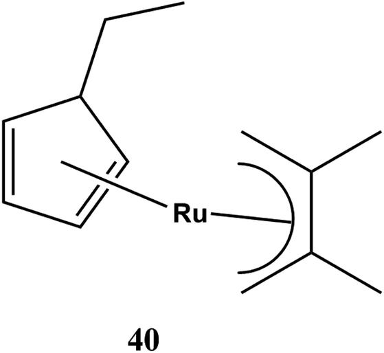 | ||
| Fig. 11 Molecular structure of [Ru(DMPD)(EtCp)] 40. | ||
In this context, Kawano et al.136 had reported that decomposition temperature of [Ru(DMPD)(EtCp)] 40 was 270 °C, which was 80 °C lower than that of [Ru(EtCp)2]. It owes to change of one ligand from alkyl-substituted cyclopentadienyl group to an alkyl-substituted linear pentadienyl group. The [Ru(DMPD)2] with two alkyl-substituted linear pentadienyl ligand decomposed at 210 °C which is 60 °C lower than [Ru(DMPD)(EtCp)]. Thus, it showed that [Ru(DMPD)2 may be a useful MOCVD precursor.
The study136 showed that [Ru(DMPD)2] can be used in a wider range of deposition temperature in the transported limited temperature regime as compare to [Ru(DMPD)(EtCp)]. The thin films of [Ru(DMPD)2] can be deposited below 200 °C whereas film deposition for [Ru(DMPD)(EtCp)] was found only above 250 °C.
One interesting dinuclear complex of cyclopentadiene [Ru(C5H5(CO)2)2] 41 as shown in Fig. 12, formed pure, conductive, conformal ruthenium films on patterned Si3N4 and on flat barium strontium titanate BST in the presence of oxygen carrier gas.137 [Ru(C5H5(CO)2)2] 41 has labile CO ligands as leaving groups decrease the decomposition temperature (Fig. 12).
 | ||
| Fig. 12 Molecular structure of [Ru(C5H5(CO)2)2] 41. | ||
Pure Ru thin films were deposited on Si substrate using [Ru(OD)3] 42 (OD = octanedionate) by metalorganic chemical vapor deposition (MOCVD). The study showed that deposition of thin film depend on MOCVD process parameters such as deposition temperature, O2/(O2 + Ar) ratio, and reactor pressure.138,139
Cyclopentadienyl complexes of previously synthesized ruthenium allylic derivative such as [Ru(η3-C3H5)2(COD)] 43 (Fig. 13), COD = 1,4-cyclooctadiene,140 had been extensively studied as CVD precursor at low temperatures on α-Al2O3 and surface oxidized Si(100) in N2, N2 + H2, N2 + O2, or O2 flow.141 It was observed that H2 addition increased the metal purity and decreased the grain sizes.
 | ||
| Fig. 13 Molecular structure of [Ru(η3-C3H5)2(COD)] 43. | ||
Barison et al. also studied nanocrystalline RuO2 and Ru films obtained from Ru(COD)(η3-allyl)2 (COD = cycloocta-1,5-diene) on metallic titanium discs at a temperature of 300 °C by the electrocatalytic O2 evolution.142,143
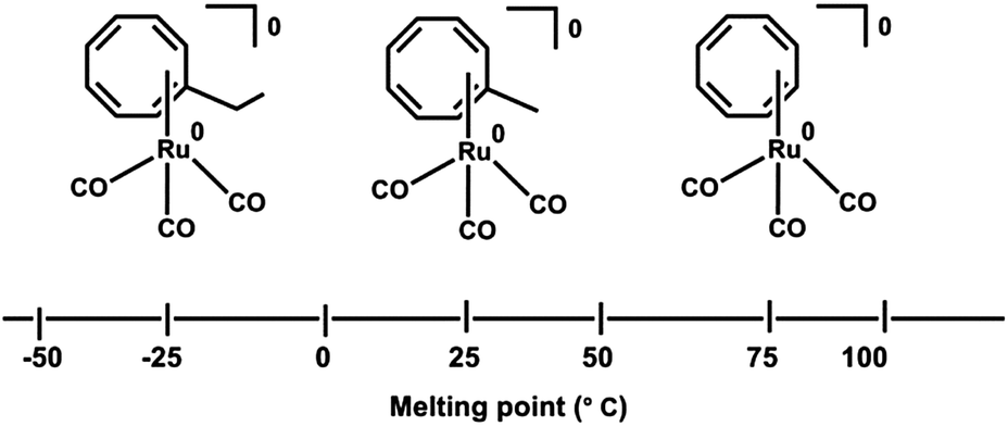
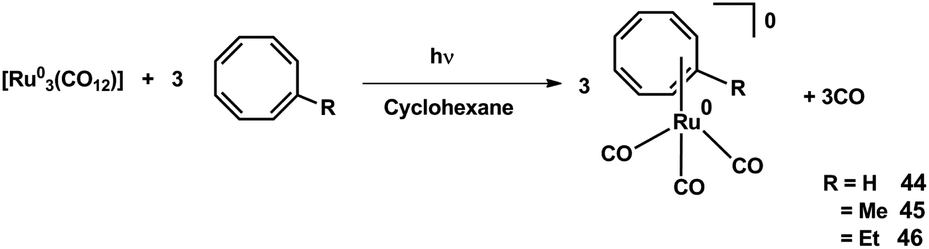
Recently, Ando et al.144 reported the synthesis of a series of Ru(0) cyclooctatetraene complexes for MOCVD (metal organic chemical vapor deposition) applications. A melting point relation of the CVD precursors is reported and shown in Fig. 14. The melting point increases with the decrease in alkyl substituent at cyclooctatetraene ring.
 | ||
| Fig. 14 Structure and Melting points CVD precursor 44–46. Adapted from ref. 144. | ||
The synthetic strategy of Ru(0) COT complexes, [(η4-COT-R)(CO)3 Ru(0)] (R = H: 44, Me: 45, Et: 46), COTR = R-cycloocta-1,3,5,7-tetraene for MOCVD is depicted in Scheme 12. Conformal ruthenium films were deposited on SiO2 substrates even within holes with aspect ratios of 40![[thin space (1/6-em)]](https://www.rsc.org/images/entities/char_2009.gif) :1. The ruthenium film formation improves by the introduction of methyl and ethyl group into the COT ligand.
:1. The ruthenium film formation improves by the introduction of methyl and ethyl group into the COT ligand.
 | ||
| Scheme 12 Synthesis of CVD precursor 44–46. Adapted from ref. 144. | ||
(c) Ruthenium derivatives containing N-donor ligands
N-donor ligands may be an interesting alternative to the precursors discussed so far. Since CVD precursors are mostly governed by the ligand frameworks, it may be helpful to enlist some selected nitrogen donors in Fig. 15. These nitrogen donors were used as ligands in transition metal complexes.145 | ||
| Fig. 15 Some nitrogen donor ligands. | ||
In 2003, Carty and co-workers reported the synthesis and structure of double pyrazolate bridged ruthenium complexes [(CO)3Ru(3,5-(CF3)2Pz)]247 and 48 {3,5-(CF3)2Pz = 3,5-bis(trifluoromethyl)pyrazole} at low temperature 180 °C which exhibited superior volatility as compared to its parent compound Ru3(CO)12 and closely related 3,5,di-tert-butyl pyrazole complex [Ru2(CO)5(3,5-t-Bu2-pz)2] for its practical use in CVD.146,147 The introduction of CF3 groups in pyrazole moiety increases the volatility of the bridged ruthenium complex 47 as compared to complex 48. The synthetic route for the preparation is shown in Scheme 13 and the structure of the complex as derived from X-ray diffraction is depicted in Fig. 16.
 | ||
| Scheme 13 Synthesis and molecular structure of pyrazolate bridged ruthenium complexes. Adapted from ref. 147. | ||
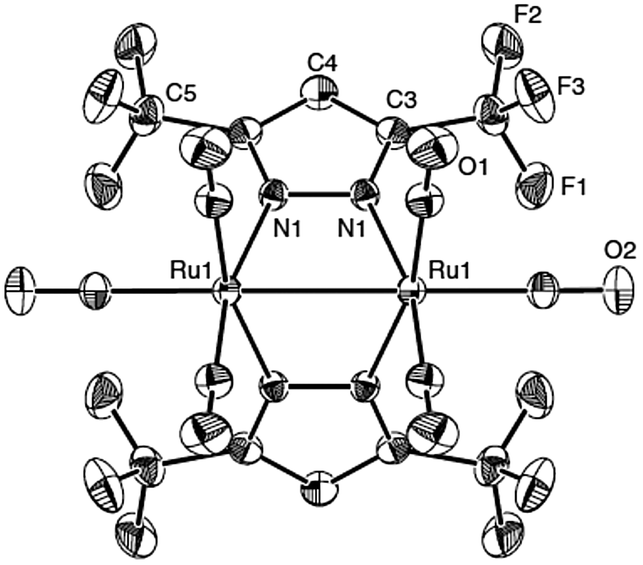 | ||
| Fig. 16 The structure of pyrazolate bridged ruthenium complex. Source ref. 147. | ||
Chou et al.78 synthesized two octahedral Ru(III) complexes such as [Ru(keim1)3] 49 and [Ru(keim2)3] 50, (keim1 = –OC(CF3) = CHC–CH3 = NMe, keim2 = –OC(CF3) = CHC–CF3 = NMe) with good volatility and thermal stability. The CVD study showed that the film structures varied according to the nature of source reagent and carrier gas. [Ru(keim1)3] lead to the formation of a (002) preferred orientation using a mixture of 2% O2 in argon or pure O2 as carrier gas, while [Ru(keim2)3] yielded a randomly oriented Ru thin film. The physical properties such as temperature, of the complexes can seriously affect the kinetics and mechanism of RuO2 growth behaviour. The formation of (200) growth of RuO2 columnar thin films is observed when [Ru(keim1)3] is used in pure O2 carrier gas at 1 atm below 270 °C (Fig. 17).
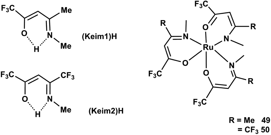 | ||
| Fig. 17 Structure of CF3 substituted ketoimine ligands. | ||
Li et al. reported high purity (0.2% impurities) fine-grained polycrystalline ruthenium thin film deposition obtained from a volatile ruthenium amidinate precursor [Ru(Bu-Me-amd)2(CO)2] 51, bis(N,N-di-tert-butylacetamidinato) ruthenium(II)dicarbonyl without any coreactant via pulsed CVD at above 300 °C.148 The molecular structure and crystal structure of Ru amidinate precursor as shown in Fig. 18 and 19.
 | ||
| Fig. 18 Molecular structure of [Ru(Bu-Me-amd)2(CO)2] 51. | ||
 | ||
| Fig. 19 Crystal structure of [Ru(Bu-Me-amd)2(CO)2]. | ||
For thin film formation, they proposed a thermal decomposition mechanism as shown in Scheme 14. It shows that [Ru(Bu-Me-amd)2(CO)2] 51 decomposes by releasing carbon monoxide and the ligand dimer.
 | ||
| Scheme 14 Mechanism of ruthenium thin deposition from [Ru(Bu-Me-amd)2(CO)2]. Adapted from ref. 136. | ||
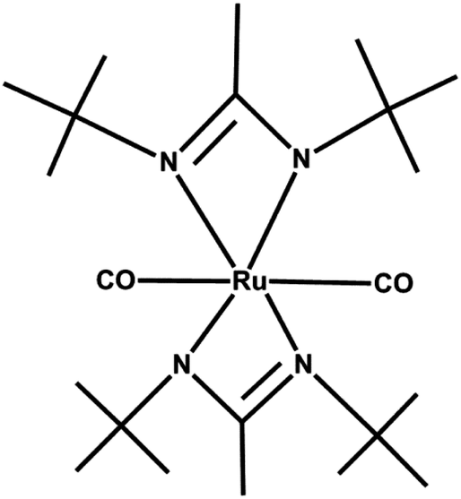
In this class of ruthenium complexes, three new amidinate complexes of types tris(diisopropylacetamidinato)-ruthenium(III) [Ru(iPrNC(Me)NiPr)3] 52, bis(diisopropyl-acetamidinato)ruthenium(II) dicarbonyl [Ru(iPrNC(Me)NiPr)2 (CO)2] 53 and bis(di-tert-butylacetamidinato)ruthenium(II) dicarbonyl [Ru(tBuNC(Me)NtBu)2(CO)2], 54 were found to be sufficiently volatile and thermally stable and thus suitable for chemical vapor deposition.149 A schematic view of their synthesis is shown in Scheme 15. Starting materials mer-RuCl3(MeS)3, [RuCl2(CO)3]2, and RuCl2(CO)3(C4H8O) which have relatively high solubility in ether or THF, were suitable for the synthesis of ruthenium amidinate compounds with quite good yields.
 | ||
| Scheme 15 Synthesis of Ru amidinate 52–54. Adapted from ref. 149. | ||
These compounds owing to the formation of a Ru–N bond, are found to be reactive towards hydrogen (forming Ru), water (forming oxide) and ammonia (forming nitrides) with minimal impurities of carbon and oxygen in the deposited films. However, complexes containing Ru–C bonds lack a sufficient reactivity with hydrogen, water and ammonia.148 Thus, in general, the advantages of the metal amidinate precursors include sufficient volatility, low deposition temperature, high thermal stability and good quality of the formed films. The physical characteristics of these newly synthesized compounds 52–54 are listed in a Table 4.
| Vapor pressure (°C/Torr) | M.P./°C | Color | T 1/2 (h) | |
|---|---|---|---|---|
| 52 | 85/0.05 | >250 | Blue | 15 |
| 53 | 50/0.045 | 122 | Yellow | n/a |
| 54 | 130/0.055 | 204 | Pale yellow | 44 |
(d) Miscellaneous ruthenium CVD precursors
As mentioned earlier, Ru thin film deposition often follows a Volmer–Weber growth mechanism. Due to the high surface energy and due to much faster diffusion at grain boundaries this leads to polycrystalline, columnar films.150 For a good microstructure of Ru films, an improvement in the barrier properties are essential.151 As changing the Ru film microstructure from polycrystalline to nanocrystalline should eliminate or suppress the fast diffusion through grain boundaries and increase the film nucleation and deposition rate. It is also believed that the choice of precursors and reaction conditions can strongly influence both, the composition and the size of thin film. In this context, some other precursors including other atoms which may lead to the formation of Ru containing films in CVD will be discussed here.Huang et al. reported152 a mixed Pt–Ru complex [CpRu(η5-C5H3CH2NMe2)Pt(DMSO)Cl] 55 which is highly volatile. The deposition of thin films from this compound at lower temperature leads to highly dispersed Pt–Ru binary alloys. However, the phase separation of the initially homogenous Pt–Ru was observed upon raising the temperature to 400 °C (Scheme 16).
 | ||
| Scheme 16 Synthetic strategy of [CpRu(η5-C5H3CH2NMe2)Pt(DMSO)Cl] 55. Adapted from ref. 152. | ||
Kang et al. also reported Pt-doped Ru thin films using cyclopentadienyl-propylcyclopentadienlylruthenium(II) and (trimethyl)methylcyclo pentadienlylplatinum(IV) 56 as the Ru and Pt CVD precursors (Fig. 20).74
 | ||
| Fig. 20 Crystal structure of [CpRu(η5-C5H3CH2NMe2)Pt(DMSO)Cl] depicting the binding mode. Source ref. 152. | ||
In 2006, Shin et al.153 explored highly conformal, smooth films of amorphous ruthenium–phosphorus alloy (RuP) using cis-H2Ru(PMe3)4 (Me = CH3) which contains Ru–H and Ru–P bonds. The CVD process depends on the ligand selection: In cis-H2Ru(PMe3)457, the PMe3 ligands is a highly volatile leaving group whereas the Ru–H bond facilitate a dissociative adsorption. Growth of highly conformal, smooth films of amorphous RuP alloys were formed after the complete demethylation of PMe3 on Ru(0001) at 500 K. The chemical composition of this precursor has a direct influence on both the elemental composition and morphology of the grown films. A further detailed study of this precursor154 describes that the films remain amorphous even upon heating for 3 h at 635 K, and only begin to crystallize upon annealing at 775 K for 30 min in vacuum. Furthermore, it is believed that heteroatom incorporation interferes with crystallite formation, since the as-deposited films are X-ray amorphous showing no long range order. Further McCarty et al.155 extended this concept and prepared some new ruthenium phosphite hydride complexes H2Ru(P(OR)3)4 (R = Me 58, Et 59 or iPr 60) in order to determine the possible effects of precursor ligand chemistry on film morphology and composition. The incorporation of trialkylphosphite (P(OR)3) over trialkyl phosphine as they are more air stable and less expensive. The composition of the films was found to depend on the ligand chemistry as well as on the deposition conditions. The use of H2 as the carrier gas had the effect of increasing the relative concentrations of P and O for all films. The crystal structure of [H2Ru(P(OMe)3)4] is depicted in Fig. 21.
 | ||
| Fig. 21 Crystal structure of [H2Ru(P(OMe)3)4]. Source ref. 155. | ||
In the formation of ruthenium thin films, mainly carbon impurities have been present owing to insufficient oxidant supply during the deposition process. The co-deposited C may hinder the grain growth of metal particles, resulting in the formation of nanoparticle with significantly large surface area. For utilization of this property in 2007, Sakata et al.156 reported ruthenium–carbon (Ru–C) nano-composite films which were prepared by plasma-enhanced chemical vapor deposition (PECVD) in the presence of Ar gas using [Ru(dpm)3] or [Ru(tmhd)3] (dipivaloylmethanate) 61 as ruthenium precursors (Fig. 22). Ruthenium thin films were formed as (10 to 20 nm) agglomerated grains with 2.5 to 3.5 nm of Ru particles in a carbon matrix. The interfacial electrical conductivity is calculated 0.2 × 10⁻³ S m−1 at the Ru–C/YSZ interface (Ru–yttria-stabilized zirconia solid electrolyte) at 500 K.
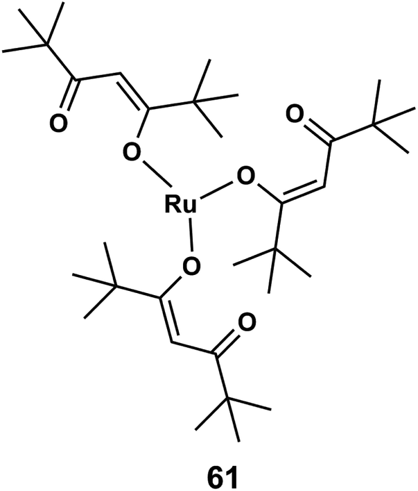 | ||
| Fig. 22 Structure of dipivaloylmethanate ruthenium or Ru(tmhd)3. | ||
Li et al.157 also explored a single source precursor heteronuclear carbonyl cluster [RuOs3(CO)13(μ-H)2] 62 for the preparation of thin films of Os–Ru binary alloy. The ratio of osmium to ruthenium varied with the deposition temperature, and at higher temperatures (400–500 °C) the deposited surface was smoother. The structure of the cluster represented in Fig. 23.
 | ||
| Fig. 23 Molecular structure of mixed Os–Ru carbonyl cluster 62. | ||
Recently Popovska et al. prepared carbon nanotubes by catalytic chemical vapor deposition (CCVD) with the help of iron, ruthenium and bimetallic Fe/Ru nanoparticles on spNaY zeolite support and acetylene as the carbon source.158 The nanoparticle catalysts 63 were prepared by fluidized bed metal organic chemical vapor deposition (FB-MOCVD) using ruthenium precursor [(benzene)(1,3-cyclohexadiene)Ru(0)] and form CNTs with low 0.05 wt% Ru concentrations. The crystalline solid ruthenium thin film deposition occurs as the formation of metal nanoparticles at oxidic surfaces. The deposition scheme is presented in Scheme 17.
 | ||
| Scheme 17 [(Arene)(diene)Ru(0)] 63 metal organic precursor complexes used for the metal catalysts deposition. Adapted from ref. 158. | ||
In 2011, Bouanis et al. reported single-walled carbon nanotubes (SWCNTs) growth on Ru nanoparticle catalyst 64 synthesized by RuTTP complex (5,10,15,20-tetraphenyl-21H,23H-porphine ruthenium(II)) via chemical vapor deposition as represented in Fig. 24.159 Self assembled monolayers of Ru tetraphenyl porphyrins (RuTPP) were used as catalyst on the SiO2/Si(100) growth substrates pre-functionalized by silanization to form a pyridine terminated molecular monolayer by HFCVD (hot filament CVD).
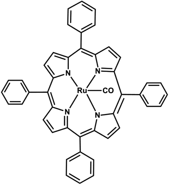 | ||
| Fig. 24 Structure of 5,10,15,20-tetraphenyl-21H,23H-porphine ruthenium(II) carbonyl 64. | ||
Recently, nanoparticles from dodecatriruthenium dodecacarbonyl Ru3(CO)1265 were also explored for ruthenium deposition on SiO2/Si(001) substrates at 473 K with and without an overpressure of CO by Liao et al.160 A highly smooth thin film is obtained by carbon monoxide addition during growth. The reaction kinetics showed that the addition of CO to the reaction, chamber reduces the Ru nanoparticle density by limiting the Ru adatom formation at hydroxyl sites as depicted in Fig. 25. The gas CO also adsorbs on the surface of Ru nanoparticles and facilitates the ruthenium island formation. The addition of CO with proper timing and effective partial pressure decreases the film growth rate, surface roughness, and nanocrystalline grain growth. Carbon monoxide was employed to inhibit the growth of previously nucleated islands to allow the formation of additional nuclei. After inhibition of growth, previously nucleated islands of ruthenium allow the formation of additional nuclei. The CO blocks the free hydroxyls present on the silica substrate where the Ru precursor adsorption and decomposition occurs. After two hours, thinner and smoother ruthenium thin films were obtained compared to a deposition without CO for 10 min because CO adsorption on the Ru surface slows the Ru island growth rate.
 | ||
| Fig. 25 Schematic diagram of CO addition to Ru CVD at different times as compared to deposition without CO. Adapted from ref. 160. | ||
In summary, an introduction of F over H on diketonate and pyrazolate ruthenium precursors increases the volatility leading to the formation of thin film layer formation. However, carboxyl groups bearing ruthenocene complexes show a higher volatility compared to the corresponding ruthenocenes. Introduction of trimethyl silyl groups in organometallic ruthenium precursors also induces both, higher vapor pressures and lower melting points. As compared to [(benzene)(1,3-cyclohexadiene)Ru(0)], its alkyl substituted derivatives also improves the CVD properties.
5. Conclusion
In this review, we have discussed a variety of ruthenium precursors for chemical vapor deposition that have been reported in last few years. Exciting progress has been made during the past few decades in the synthesis and electronic applications of ruthenium precursors to form pure films using developed methodology and have been attempted to present an up-to-date overview of this rapidly growing field of research. For those unfamiliar with CVD, a brief introduction of the CVD technique and significant applications of CVD films are given. The examples collected in the present review focus mainly on ruthenium based organometallics, carbonyls, diketonates and nitrogen containing derivatives. It is observed that small changes in the ligand frame work in the periphery of ruthenium precursors can significantly influence properties which in turn can have a distinct effects in the properties of the deposited thin films. Mainly different bond strengths of C–H and C–C bond compared to Ru–C or Ru–O bonds are important regarding the decomposition pathways and temperature regimes for CVD. These properties also directly influence the carbon contamination within the films. Further improvements seem possible here, also including theoretical evaluation methods to estimate bond strengths in designed precursors prior to their synthesis. But theory, in general, cannot provide good estimates regarding vapor pressures, while reasonably high vapor pressures are a crucial prerequisite for CVD. At the end careful experiments will be needed to investigate the difference of evaporation temperature and deposition temperature of a given precursor.The properties of the deposited films are intrinsically coupled to the properties of the precursors, thus further progress regarding typical properties like specific conductivity can be expected with improved precursor design. As seen, quite often a compromise must be found between the desired precursor and film properties and the price of the precursors, and thus of the production. Many material chemists are actively involved in this promising field, and hence, the synthesis of new highly efficient and advanced ruthenium precursors for CVD is still demanding.
Acknowledgements
Authors (LM, RG) gratefully acknowledge INSA-DFG and CSIR New Delhi, India for their financial assistance.References
- E. Kondoh, Jpn. J. Appl. Phys., 2005, 44, 5799–5802 CrossRef CAS.
- G. C. Bond and J. C. Slaa, J. Mol. Catal. A: Chem., 1995, 101, 243–253 CrossRef CAS.
- P. Jakob and D. Menzel, Surf. Sci., 1988, 210(3), 503–530 CrossRef.
- M. C. Sanchez Sierra, J. García Ruiz, M. G. Proietti and J. Blasco, J. Mol. Catal. A: Chem., 1995, 96, 65–75 CrossRef CAS.
- J. U. Köhler and H. L. Krauss, J. Mol. Catal. A: Chem., 1997, 123, 49–64 CrossRef.
- A. Schneider, N. Popovska, I. Jipa, B. Atakan, M. A. Siddiqi, R. Siddiqui and U. Zenneck, Chem. Vap. Deposition, 2007, 3, 389–395 CrossRef , and references therein.
- K. Gregorczyk, L. Henn-Lecordier, J. Gatineau, C. Dussarrat and G. Rubloff, Chem. Mater., 2011, 23, 2650–2656 CrossRef CAS.
- T. Kawahara, M. Yamamuka, A. Yuuki and K. Ono, Jpn. J. Appl. Phys., 1996, 35, 4880–4885 CrossRef CAS.
- A. Tsuzumitani, Y. Okuno, J. Shibata, T. Shimizu, K. Yamamoto and Y. Mori, Jpn. J. Appl. Phys., 2000, 39, 2073–2077 CrossRef CAS.
- N. Inoue, N. Furutake, A. Toda, M. Tada and Y. Hayashi, IEEE Trans. Electron Devices, 2005, 52(10), 2227–2235 CrossRef CAS.
- T. Furukawa, T. Kuroiwa, Y. Fujisaki, T. Sato and H. Ishiwara, Jpn. J. Appl. Phys., 2005, 44, L378–L380 CrossRef CAS.
- D. Bekermann, D. Barreca, A. Gasparotto and C. Maccato, CrystEngComm, 2012, 14, 6347–6358 RSC.
- M. Damayanti, T. Sritharan, Z. H. Gan, S. G. Mhaisalkar, N. Jiang and L. Chan, J. Electrochem. Soc., 2006, 153, J41–J45 CrossRef CAS PubMed.
- M. S. Mudholkar and L. T. Thompson, J. Appl. Phys., 1995, 77, 5138 CrossRef CAS PubMed.
- G. R. Harp and S. S. P. Parkin, Thin Solid Films, 1996, 288, 315–324 CrossRef CAS.
- R. Triboulet and J. Perriere, Prog. Cryst. Growth Charact. Mater., 2003, 47, 65–138 CrossRef CAS PubMed.
- P. S. Patil, E. A. Ennaoui, C. D. Lokhande, M. Müller, M. Giersig, K. Diesner and H. Tributsch, Thin Solid Films, 1997, 310, 57–62 CrossRef CAS.
- Q. X. Xia, X. D. Wu, G. Song and S. R. Foltyn, J. Vac. Sci. Technol., A, 1996, 14, 1107–1111 Search PubMed.
- Y. Gao, G. Bai, Y. Liang, G. C. Dunham and S. A. Chambers, J. Mater. Res., 1997, 12, 1844–1849 CrossRef CAS.
- I. Zhitomirsky, Mater. Lett., 1998, 33, 305–310 CrossRef CAS.
- K. Kameyama, S. Shohji, S. Onoue, K. Nishimura, K. Yahikozawa and Y. Takasu, J. Electrochem. Soc., 1993, 140, 1034–1037 CrossRef CAS PubMed.
- J. R. V. Gracia and T. Goto, Mater. Trans., 2003, 44, 1717–1728 CrossRef.
- D.-J. Lee, S.-W. Kang and S.-W. Rhee, Thin Solid Films, 2002, 413, 237–242 CrossRef CAS.
- J. Sankar, T. K. Sham and R. J. Puddephatt, J. Mater. Chem., 1999, 9, 2439–2444 RSC.
- B. Borca, S. Barja, M. Garnic, M. Minniti, A. Politano, J. M. Rodriguez-García, J. J. Hinarejos, D. Farías, A. L. V. de Parga and R. Miranda, New J. Phys., 2010, 12, 093018–093035 CrossRef.
- A. Politano, D. Campi, V. Formosoac and G. Chiarello, Phys. Chem. Chem. Phys., 2013, 15, 11356–11361 RSC.
- A. Politano and G. Chiarello, Carbon, 2013, 61, 412–417 CrossRef CAS PubMed.
- W. Feng, S. Lei, Q. Li and A. Zhao, J. Phys. Chem. C, 2011, 115, 24858–24864 CAS.
- E. Sutter, P. Albrecht and P. Sutter, Appl. Phys. Lett., 2010, 97, 213101 CrossRef PubMed.
- E. Sutter, P. Albrecht and P. Sutter, Appl. Phys. Lett., 2010, 97, 213101 CrossRef PubMed.
- E. Sutter, P. Albrecht and P. Sutter, Appl. Phys. Lett., 2009, 95, 133109 CrossRef PubMed.
- A. Politano, B. Borca, M. Minniti, J. J. Hinarejos, A. L. Vázquez de Parga, D. Farías and R. Miranda, Phys. Rev. B: Condens. Matter Mater. Phys., 2011, 84, 035450 CrossRef.
- B. Holst and W. Allison, Nature, 1997, 390, 244 CrossRef CAS PubMed.
- A. Politano and G. Chiarello, Appl. Phys. Lett., 2013, 102, 201608 CrossRef PubMed.
- A. Politano and G. Chiarello, Nanoscale, 2013, 5, 8215 RSC.
- H. Yan, X. Li, B. Chandra, G. Tulevski, Y. Wu, M. Freitag, W. Zhu, P. Avouris and F. Xia, Nat. Nanotechnol., 2012, 7, 330 CrossRef CAS PubMed.
- M. Schwander and K. Partes, Diamond Relat. Mater., 2011, 20, 1287–1301 CrossRef CAS PubMed.
- J. R. Creighton and P. Ho, Introduction to Chemical vapor Deposition (CVD), in Chemical Vapor Deposition, ed. J. H. Park and T. S. Sudarshan, ASM International, Materials Park, OH, 2001 Search PubMed.
- Chemical vapor deposition (Surface engineering series), ed. J. H. Park and T. S. Sudarshan, ASM International, 2001 Search PubMed.
- U. Bergmann, K. Lummer, B. Atakan and K. Kohse-Höinghaus, Ber. Bunsen-Ges., 1998, 102(7), 906–914 CrossRef CAS.
- Thin Film Processes, ed. John L. Vossen and Werner Kern, academic press inc (Landon) Ltd., 1978, pp. 73–3348 Search PubMed.
- U. Bergmann, V. Reimer and B. Atakan, Phys. Chem. Chem. Phys., 1999, 1(24), 5593–5599 RSC.
- T. Haase, K. Kohse-Höinghaus, B. Atakan, H. Schmidt and H. Lang, Chem. Vap. Deposition, 2003, 9(3), 144–148 CrossRef CAS.
- A. C. Jones and P. O'Brien, General Materials Science, C[VD of Compound Semiconductors: Precursor Synthesis, Developmeny and Applications, 2008, pp. 1–352 Search PubMed.
- C. A. D. Dion and J. R. Tavares, Powder Technol., 2013, 239, 484–491 CrossRef PubMed.
- W. Kern and V. Ban in Chemical Vapor Deposition of Inorganic Thin Films, ed. John L. Vossen and Werner Kern, Academic Press, 1978, pp. 257–331, and references there in Search PubMed.
- D. W. Hess, K. F. Jensen and T. J. Anderson, Rev. Chem. Eng., 1985, 3, 99–176 Search PubMed and references there in.
- C. Pflitsch, D. Viefhaus, U. Bergmann, V. Kravets, H. Nienhaus and B. Atakan, J. Electrochem. Soc., 2006, 153(8), C546–C550 CrossRef CAS PubMed.
- G. D. Papasouliotis and S. V. Sotirchos, J. Mater. Res., 1999, 14(8), 3397–3409 CrossRef CAS.
- D. W. Shaw, J. Cryst. Growth, 1975, 31, 130 CrossRef CAS.
- Y. Kangawa, T. Akiyama, T. Ito, K. Shiraishi and T. Nakayama, Materials, 2013, 6, 3309–3361 CrossRef CAS PubMed.
- T. Hur'yeva, M. Lisker and E. P. Burte, Chem. Vap. Deposition, 2006, 12, 429–434 CrossRef.
- P. Hones, F. Lévy, T. Gerfin and M. Grätzel, Chem. Vap. Deposition, 2000, 6(4), 193–198 CrossRef CAS.
- L. Liu, H. Zhou, R. Cheng, Y. Chen, Y.-C. Lin, Y. Qu, J. Bai, I. A. Ivanov, G. Liu, Y. Huang and X. Duan, J. Mater. Chem., 2012, 22, 1498–1503 RSC.
- R. A. Levy, J. M. Grow and G. S. Chakravarthy, Chem. Mater., 1993, 5(12), 1710–1714 CrossRef CAS.
- G. Luo, P. Zhu, P. Chen, Z. Liu, H. Lin and P. Qian, Vacuum, 2000, 59, 927–931 CrossRef CAS.
- H. O. Pierson, Handbook of chemical vapor deposition, Park Ridge, Noyes, 1992 Search PubMed.
- M. L. Hitchman and A. C. Jones, Chemical Vapor Deposition: Precursors, Processes and Applications, 2009 Search PubMed; M. L. Hitchman and A. C. Jones, Chemical Vapor Deposition: Principles and Applications, Academic Press, 1993 Search PubMed.
- J. Tavares, E. J. Swanson and S. Coulombe, Plasma Processes Polym., 2008, 5(8), 759–769 CrossRef CAS and references there in.
- G. Wahl, P. B. Davies, R. F. Bunshah, B. A. Joyce, C. D. Bain, G. Wegner, M. Remmers, F. C. Walsh, K. Hieber, J.-E. Sundgren, P. K. Bachmann, S. Miyazawa, A. Thelen, H. Strathmann and K. J. Edler, Ullmann's Encyclopedia of Industrial Chemistry, 2014, pp. 1–75 Search PubMed.
- E. H. A. Granneman, Thin Solid Films, 1993, 228, 1–11 CrossRef CAS.
- G. Kalita, M. S. Kayastha, H. Uchida, K. Wakitaa and M. Umenoa, RSC Adv., 2012, 2, 3225–3230 RSC.
- V. Shanov, W. Tabakoff and R. N. Singh, J. Mater. Eng. Perform., 2002, 11, 220–225 CrossRef CAS.
- R. Bogdanowicz, M. Smietana, M. Gnyba, M. Ficek, V. Stranák, Ł. Golunski, M. Sobaszek and J. Ryl, Phys. Status Solidi A, 2013, 1–7 Search PubMed.
- P. Török and F.-J. Kao, J. Raman Spectrosc., 2006, 37, 956–957 CrossRef.
- T. G. Brown, Optical Fibers and Fiber-Optic Communications, in Handbook of Optics, ed. M. Bass, McGraw-Hill, New York, 2nd edn, 1995, Vol. II Search PubMed.
- T. J. Cervantes, L. T. Romano and M. A. Kneissl, US 6379985 B1, 2002.
- D. T. Read and A. A. Volinsky, Micro- and opto-electronic materials and structures: Physics, mechanics, design, reliability, packaging, ed. E. Suhir, et al, Springer, New York, 2007, vol. 1, pp. 135–180 Search PubMed.
- R. Dhansekaran and P. Ramasamy, Indian J. Eng. Mater. Sci., 2000, 7, 350–353 Search PubMed.
- J. A. Venables and G. L. price, in Epitaxial Growth, ed. J. W. Matthew, Academic Press, 1975, part B, p. 382 Search PubMed.
- D. King and D. Woodruff, Growth and Properties of ultra thin Epitaxial Layers, Elsevier, 1997 Search PubMed.
- J. Shin, A. Waheed, K. Agapiou, W. A. Winkenwerder, H.-W. Kim, R. A. Jones, G. S. Hwang and J. G. Ekerdt, J. Am. Chem. Soc., 2006, 128, 16510–16511 CrossRef CAS PubMed.
- G. B. Stringfellow, J. Cryst. Growth, 1984, 68, 111–120 CrossRef CAS.
- S. Y. Kang, C. S. Hwang and H. J. Kim, J. Electrochem. Soc., 2005, 152(1), C15–C19 CrossRef CAS PubMed and references there in.
- L. McElwee-White, Dalton Trans., 2006, 5327–5333 RSC.
- D. H. Jang and J. S. Chun, J. Vac. Sci. Technol., A, 1989, 7(1), 31–35 CAS.
- A. C. Jones, J. Mater. Chem., 2002, 12, 2576–2590 RSC.
- T. Y. Chou, Y. H. Lai, Y. L. Chen, Y. Chi, K. R. Prasad, A. J. Carty, S. M. Peng and G. H. Lee, Chem. Vap. Deposition, 2004, 10, 149–158 CrossRef CAS.
- K. C. Smith, Y.-M. Sun, N. R. Mettlach, R. L. Hance and J. M. White, Thin Solid Films, 2000, 376, 73–81 CrossRef CAS.
- P. C. Liao, Y. S. Huang and K. K. Tiong, J. Alloys Compd., 2001, 98, 317–318 Search PubMed.
- M. A. Siddiqi and B. Atakan, Thermochim. Acta, 2007, 452, 128–134 CrossRef CAS PubMed.
- Y. Chi, S. Ranjan, P.-W. Chung, C.-S. Liu, S. M. Peng and G.-H. Lee, J. Chem. Soc., Dalton Trans., 2000, 343–347 RSC.
- B. D. Fahlman and A. R. Barron, Adv. Mater. Opt. Electron., 2000, 10, 223–232 CrossRef CAS.
- E. I. Tsyganova and L. M. Dyagileva, Russ. Chem. Rev., 1996, 65(4), 315–328 CrossRef PubMed and references there in.
- G. G. Condorelli, G. Malandrino and I. L. Fragal, Coord. Chem. Rev., 2007, 251, 1931–1950 CrossRef CAS PubMed.
- Z. Yuan, R. J. Puddephatt and M. Sayer, Chem. Mater., 1993, 5, 908–910 CrossRef CAS.
- S. E. Park, H. M. Kim, K. B. Kim and S. H. Min, J. Electrochem. Soc., 2000, 147(1), 203–209 CrossRef CAS PubMed references therein.
- A. D. Berry, D. J. Brown, R. Kaplan and E. J. Cukauskas, J. Vac. Sci. Technol., A, 1986, 4, 215–218 CAS.
- A. Z. Rubezhov, Platinum Met. Rev., 1992, 36, 26–33 CAS and references there in.
- Q. Wang, J. G. Ekerdt, D. Gay, Y.-M. Sun and J. M. White, Appl. Phys. Lett., 2004, 84(8), 1380–1382 CrossRef CAS PubMed.
- Y. Senzaki, F. B. McCormick and W. L. Gladfelter, Chem. Mater., 1992, 4, 747–749 CrossRef CAS.
- T. Aaltonen, M. Ritala, K. Arstila, J. Keinonen and M. Leskelä, Chem. Vap. Deposition, 2004, 10, 215–219 CrossRef CAS.
- L. Wolf, E. Butter and H. Weinelt, Z. Anorg. Allg. Chem., 1960, 306, 87–93 CrossRef CAS.
- D. Rose and G. Wilkinson, J. Chem. Soc. A, 1970, 1791–1795 RSC.
- A. F. Bykov, N. B. Morozova, I. K. Igumenov and S. V. Sysoev, J. Therm. Anal., 1996, 46, 1551–1565 CrossRef CAS and references there in.
- M. Lashdaf, T. hatanpaa and M. Titta, J. Therm. Anal. Calorim., 2001, 64, 1171–1182 CrossRef CAS.
- N. B. Morozova, G. I. Zharkova, P. P. Semyannikov, S. V. Sysoev, I. K. Igumenov, N. E. Fedotova and N. V. Gelfond, J. Phys. IV, 2001, 11, 609–616 Search PubMed.
- M. A. R. D. Silva and M. L. C. C. H. Ferrao, Pure Appl. Chem., 1888, 60, 1225–1234 Search PubMed and references there in.
- M. L. Green, M. E. Gross, L. E. Papa, K. J. Schnoes and D. Brasen, J. Electrochem. Soc., 1985, 132, 2677–2685 CrossRef CAS PubMed.
- A. F. Bikov, N. B. Morozova, I. K. Igumenov and S. V. Sysoev, J. Therm. Anal., 1996, 46, 1551–1565 CrossRef.
- W. L. M. Weerts, M. H. J. M. de Croon and G. B. Marin, J. Electrochem. Soc., 1997, 144, 3213 CrossRef CAS PubMed.
- V. Y. Vasilyev, K. P. Mogilnikov and Y. W. Song, Electrochem. Solid-State Lett., 2008, 11(12), D89–D93 CrossRef CAS PubMed.
- V. Y. Vasilyev, K. P. Mogilnikov and Y. W. Song, Curr. Appl. Phys., 2009, 9, e148–e151 CrossRef PubMed.
- V. Y. Vasilyev, Russ. Microelectron., 2010, 39, 262–272 CrossRef CAS.
- J. M. Lee, J. C. Shin, C. S. Hwang, H. J. Kim and C.-G. Suk, J. Vac. Sci. Technol., A, 1998, 16(5), 2768–2771 CAS.
- G.-R. Bai, A. Wang, C. M. Foster and J. Vetrone, Thin Solid Films, 1997, 310, 75–80 CrossRef CAS.
- F.-J. Lee, Y. Chi, C.-S. Liu, P.-F. Hsu, T.-Y. Chou, S.-M. Peng and G.-H. Lee, Chem. Vap. Deposition, 2001, 7(3), 99–101 CrossRef CAS.
- Y.-H. Lai, Y.-L. Chen, Y. Chi, C.-S. Liu, A. J. Carty, S.-M. Pengc and G.-H. Lee, J. Mater. Chem., 2003, 13, 1999–2006 RSC.
- W.-Y. Cheng, L.-S. Honga, J.-C. Jianga, Y. Chib and C.-C. Lin, Thin Solid Films, 2005, 483, 31–37 CrossRef CAS PubMed.
- H. Z. Yu and C. V. Thompson, Acta Mater., 2014, 67, 189–198 CrossRef CAS PubMed.
- Y.-H. Lai, T.-Y. Chou, Y.-H. Song, C.-S. Liu, Y. Chi, A. J. Carty, S.-M. Peng and G.-H. Lee, Chem. Mater., 2003, 15, 2454–2462 CrossRef CAS.
- Y. Chi, P.-F. Hsu, C.-S. Liu, W.-L. Ching, T.-Y. Chou, A. J. Carty, S.-M. Peng, G.-H. Lee and S.-H. Chuang, J. Mater. Chem., 2002, 12, 3541–3550 RSC.
- Y.-L. Chen, C.-S. Liu, Y. Chi, A. J. Carty, S.-M. Peng and G.-H. Lee, Chem. Vap. Deposition, 2002, 8, 17–20 CrossRef CAS.
- Y. Chi, F. J. Lee and C.-S. Liu, US6303809 B1, 2001.
- D. Morquardt, J. Barthel, M. Braun, C. Ganter and C. Janiak, CrystEngComm, 2012, 14, 7607–7615 RSC and references there in.
- T. Aoyama and K. Eguchi, Jpn. J. Appl. Phys., 1999, 38(10A), L1134–L1136 CAS.
- S. Y. Kang, K. H. Choi, S. K. Lee, C. S. Hwang and H. J. Kim, J. Electrochem. Soc., 2000, 147(3), 1161–1167 CrossRef CAS PubMed.
- G. Wilkinson, J. Am. Chem. Soc., 1952, 74, 6146–6147 CrossRef CAS.
- D. E. Bublitz, W. E. McEwen and J. Kleinberg, Org. Synth., 1973, 5, 1001 Search PubMed.
- D. E. Trent, B. Paris and H. H. Krause, Inorg. Chem., 1964, 3(7), 1057–1058 CrossRef CAS.
- T. Aoyama and K. Eguchi, Jpn. J. Appl. Phys., 1999, 38, L1134–L1136 CAS.
- Y. Matsui, M. Hiratani, T. Nabatame, Y. Shimamoto and S. Kimura, Electrochem. Solid-State Lett., 2002, 5(1), C18–C21 CrossRef CAS PubMed.
- M. Kadoshima, T. Nabatame, M. Hiratani, Y. Nakamura, I. Asano and T. Suzuki, Jpn. J. Appl. Phys., 2002, 41(3B), L347–L350 CAS.
- T. Nabatame, M. Hiratani, M. Kadoshima, Y. Shimamoto, Y. Matsui, Y. Ohji, I. Asano, T. Fujiwara and T. Suzuki, Jpn. J. Appl. Phys., 2000, 39(11B), L1188–L1190 CAS.
- J. J. Kim, D. H. Jungb, M. S. Kim, S. H. Kim and D. Y. Yoon, Thin Solid Films, 2002, 409, 28–32 CrossRef CAS.
- S. Y. Kang, H. J. Lim, C. S. Hwang and H. J. Kim, J. Electrochem. Soc., 2002, 149(6), C317–C323 CrossRef CAS PubMed.
- D. Gan, P. S. Ho, Y. Pang, R. Huang, J. Leu, J. Maiz and T. Scherban, J. Mater. Res., 2006, 21(6), 1512–1518 CrossRef CAS.
- M. A. Siddiqi, R. A. Siddiqui, B. Atakan, N. Roth and H. Lang, Materials, 2010, 3, 1172–1185 CrossRef CAS PubMed.
- W. Trakarnpruk, A. M. Arif and R. D. Ernst, Organometallics, 1992, 11, 1686–1692 CrossRef CAS.
- A. Tuchscherer, C. Georgi, N. Roth, D. Schaarschmidt, T. Rüffer, T. Waechtler, S. E. Schulz, S. Oswald, T. Gessner and H. Lang, Eur. J. Inorg. Chem., 2012, 4867–4876 CrossRef CAS.
- J. Choi, Y. Choi, J. Hong, H. Tian, J.-S. Roh, Y. Kim, T.-M. Chung, Y. W. Oh, Y. Kim, C. G. Kim and K. No, Jpn. J. Appl. Phys., 2002, 41, 6852–6856 CrossRef CAS.
- I. Jipa, K. Danova, N. Popovska, M. A. Siddiqi, R. A. Siddiqui, B. Atakan, T. Cremer, F. Maier, H. Marbach, H.-P. Steinrück, F. W. Heinemann and U. Zenneck, J. Mater. Chem., 2011, 21, 3014–3024 RSC.
- I. Jipa, K. Danova, N. Popovska, M. A. Siddiqi, R. A. Siddiqui, B. Atakan, T. Cremer, F. Maier, H. Marbach, H.-P. Steinrück, F. W. Heinemann and U. Zenneck, J. Mater. Chem., 2011, 21, 3014–3024 RSC.
- A. Schneider, N. Propovska, F. Holzmann, H. Gerhard, C. Topf and U. Zenneck, Chem. Vap. Deposition, 2005, 11, 99–105 CrossRef CAS.
- I. Jipa, M. A. Siddiqi, R. A. Siddiqui, B. Atakan, H. Marbach, T. Cremer, F. Maier, H.-P. Steinrück, K. Danova, N. Popovska, F. W. Heinemann and U. Zenneck, Chem. Vap. Deposition, 2011, 17, 15–21 CrossRef CAS.
- K. Kawano, H. Kosuge, N. Oshima and H. Funakubo, Electrochem. Solid-State Lett., 2007, 10(6), D60–D62 CrossRef CAS PubMed.
- K. C. Smitha, Y.-M. Suna, N. R. Mettlacha, R. L. Hanceb and J. M. White, Thin Solid Films, 2000, 376, 73–81 CrossRef.
- J.-H. Lee, J.-Y. Kim, S.-W. Rhee, D. Y. Yang, D.-H. Kim, C. -H. Yang, Y.-K. Han and C.-J. Hwang, J. Vac. Sci. Technol., A, 2000, 18(5), 2400–2403 CAS.
- J.-H. Lee, J.-Y. Kim and S.-W. Rhee, Electrochem. Solid-State Lett., 1999, 2, 622–623 CrossRef CAS PubMed.
- J. Powell and B. L. Shaw, J. Chem. Soc. A, 1968, 159–161 RSC.
- D. Barreca, A. Buchberger, S. Diaolio, L. E. Depero, M. Fabrizio, F. Morandini, G. A. Rizzi, L. Sangaltti and E. Tondello, Langmuir, 1999, 15, 4537–4543 CrossRef CAS.
- S. Barison, D. Barreca, S. Daolio, M. Fabrizio and E. Tondello, J. Mater. Chem., 2002, 12, 1511–1518 RSC.
- S. Barison, D. Barreca, S. Daolio, M. Fabrizio and C. Piccirillo, Rapid Commun. Mass Spectrom., 2000, 14, 1179–1183 CrossRef CAS.
- T. Ando, N. Nakata, K. Suzuki, T. Matsumotoa and S. Ogo, Dalton Trans., 2012, 41, 1678–1682 RSC.
- P. M. S. Monk, R. J. Mortimer and D. R. Rosseinsky, Electrochromism: Fundamentals and Applications, VCH, Weinheim, 1995 Search PubMed.
- Y.-H. Song, Y.-L. Chen, Y. Chi, C.-S. Liu, W.-L. Ching, J.-J. Kai, R.-S. Chen, Y.-S. Huang and A. J. Carty, Chem. Vap. Deposition, 2003, 9, 162–169 CrossRef CAS.
- C. R. Eady, B. F. G. Johnson and J. Lewis, J. Chem. Soc., Dalton Trans., 1975, 2606–2611 RSC.
- H. Li, D. B. Farmer, R. G. Gordon, Y. Lin and J. Vlassak, J. Electrochem. Soc., 2007, 154(12), D642–D647 CrossRef CAS PubMed.
- H. Li, T. Aaltonen, Z. Li, B. S. Lim and R. G. Gordon, Open Inorg. Chem. J., 2008, 2, 11–17 CrossRef CAS and references there in.
- H. L. Skriver and N. M. Rosengaard, Phys. Rev. B: Condens. Matter Mater. Phys., 1992, 46, 7157 CrossRef CAS.
- D. Bekermann, D. Barreca, A. Gasparotto and C. Maccato, CrystEngComm, 2012, 14, 6347–6358 RSC.
- S. F. Huang, Y. Chi, C. S. Liu, A. J. Carty, K. Mast, C. Bock, B. MacDougall, S. M. Peng and G. H. Lee, Chem. Vap. Deposition, 2003, 9, 157–161 CrossRef CAS.
- J. Shin, A. Waheed, K. Agapiou, W. A. Winkenwerder, H.-W. Kim, R. A. Jones, G. S. Hwang and J. G. Ekerdt, J. Am. Chem. Soc., 2006, 128, 16510–16511 CrossRef CAS PubMed.
- J. Shin, A. Waheed, W. A. Winkenwerder, H.-W. Kim, K. Agapiou, R. A. Jones, G. S. Hwang and J. G. Ekerdt, Thin Solid Films, 2007, 515, 5298–5307 CrossRef CAS PubMed.
- W. J. McCarty, X. Yang, L. J. D. Anderson and R. A. Jones, Dalton Trans., 2012, 41, 13496–13503 RSC.
- M. Sakata, T. Kimura and T. Goto, Mater. Trans., 2007, 48(1), 58–63 CrossRef CAS.
- C. Li, W. K. Leong and K. P. Loh, Appl. Organomet. Chem., 2009, 23, 196–199 CrossRef CAS.
- N. Popovska, K. Danova, I. Jipa and U. Zenneck, Powder Technol., 2011, 207, 17–25 CrossRef CAS PubMed.
- F. Z. Bouanis, L. Baraton, V. Huc, D. Pribat and C. S. Cojocaru, Thin Solid Films, 2011, 519, 4594–4597 CrossRef CAS PubMed.
- W. Liao and J. G. Ekerdt, Chem. Mater., 2013, 25, 1793–1799 CrossRef CAS.
Footnote |
| † Current address: Department of Chemistry, Indian Institute of Technology, Kanpur-208016, India, E-mail: E-mail: ruchiuno@gmail.com. |
| This journal is © The Royal Society of Chemistry 2014 |