Xue Liu,
Shao-Fan Zhao,
Yang Shao and
Ke-Fu Yao*
School of Materials Science and Engineering, Tsinghua University, Beijing 100084, People's Republic of China. E-mail: kfyao@tsinghua.edu.cn; Fax: +86-10-62770190; Tel: +86-10-62772292
First published on 23rd July 2014
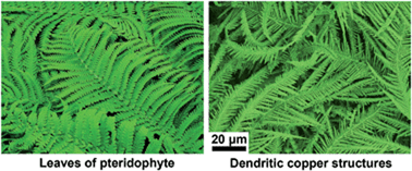
We report the facile fabrication of dendritic copper nano/submicro structures by chemical dealloying a Cu–Mn–O alloy, which breaks through the traditional thinking that complex structures cannot be obtained by simple chemical dealloying except for porous structures. The dendritic copper structures exhibit excellent air-stability at room temperature and possess high anti-oxidation properties.
Preparation of copper nano/submicro structures by dealloying attracts lots of attentions due to its widely applications in the electronic devices and sensors,14–17 but suffers from the spontaneous oxidation during the synthesis process, post-treatments and storage in atmosphere.18–20 In present work, through introducing proper amount of oxygen into Cu–Mn alloy, dendritic copper structures (DCSs) in nano/submicro scale with different morphologies were successfully prepared by simple chemical dealloying of Cu–Mn–O alloy in hydrochloric acid solution. The morphology evolution and the anti-oxidation properties of the DCSs were investigated. This work provides important insights into the preparation of anti-oxidative nano/submicro structures with different morphologies by simple chemical dealloying.
The ingots of the studied Cu–Mn–O alloy were prepared by melting the mixtures of pure Cu (99.5%) and Mn (99.0%) blocks with atom ratio of 40:
60 in argon gas condition with small amount of air to introduce proper amount of oxygen to the ingots. The ingots were cut into slice samples with ∼2 mm in thickness and ∼8 mm × 5 mm in area (∼0.8 g in weight) and dealloyed in 1 L hydrochloric acid with concentration of 0.05 M at room temperature under air atmosphere. The structures of the as-prepared sample and the dealloyed Cu–Mn–O samples were examined by Rigaku D/max-RB XRD with Cu Kα radiation at a scanning rate of 8° per min and a detecting step of 0.02°. The morphologies and the microstructures of the dealloyed samples were investigated by LEO1530 scanning electron microscope (SEM) and JEOL 2011 transmission electron microscope (TEM). The thermal stability of the dealloyed samples was investigated by Netzsch STA 449F3 differential scanning calorimetry (DSC) and thermal gravity analysis (DTA) instrument at a heating rate of 10 K min−1 in air. After oxidized at different temperatures in air, the morphologies and composition of the dealloyed samples were investigated by SEM and energy dispersive spectrometer (EDS). For comparison, a Cu40Mn60 alloy without oxygen introduced were also dealloyed under the same condition as the Cu–Mn–O sample, and the morphologies were also investigated by LEO1530 scanning electron microscope (SEM).
Before dealloying, the true composition of the Cu–Mn–O ingot was confirmed to be Cu36Mn52O12 on the surface and Cu39Mn54O7 in the core by EDS, indicating the gradient distribution of oxygen from the surface to the core in the as-prepared ingot. After dealloying, dendritic nano/submicro structures were observed on the surfaces of the dealloyed Cu–Mn–O samples, as shown in the SEM images in Fig. 1(a)–(c). By EDS analysis, the dendritic structure were confirmed to be made up of pure Cu. In the sample dealloyed for 1 day (Fig. 1(a)), the length of the DCSs is ∼50 μm and secondary dendrite arms can be observed. Through the gap of the DCSs shown in the left side of Fig. 1(a), porous surface can be observed, indicating that the DCSs grow on a porous substrate. The sample dealloyed for 2 days (Fig. 1(b)) and 26 days (Fig. 1(c)) possess similar morphology, where spreading DCSs with length beyond 100 μm and well developed tertiary dendrite arms were found. Fig. S1 in ESI† shows the SEM image of the sample dealloyed for 2 days with part of the DCSs scraped off. It can be seen that the thickness of the DCSs layer is ∼100 μm, and the DCSs grew on nanoporous structure. The enlarged SEM images of Fig. 1(a)–(c) were presented in Fig. 1(d)–(f), respectively. It can be seen that the DCSs are all highly branched and the diameter of the dendrite arms is ∼400 nm. The high-magnification image shown in the inset of Fig. 1(d) reveals that the dendrite arms of the sample dealloyed for 1 day consist of fine flake structure with thickness of ∼50 nm. While the dendrite arms of the samples dealloyed for 2 days and 26 days all consist of triangular pyramid structures with feature size of ∼400 nm, and the surface of the triangular pyramid structure tends to be smooth with the extending of the dealloying time. Thus, during the first 2 days of the dealloying process, the nano DCSs gradually formed and kept growing into submicro DCSs, then the growth stopped and the surface gradually tended to be smooth.
The XRD spectra of the as-prepared Cu–Mn–O sample and the dealloyed samples were presented in Fig. 2(a). Only a (Cu, γMn) solid solution phase was found in the spectrum of the as-prepared Cu–Mn–O sample, suggesting the as-prepared sample is mainly made up of single-phase solid solution. Since both Cu–O and Mn–O can't form solid solution at room temperature, Cu–Mn–O solid solution also can't be formed neither, and the oxygen in the Cu–Mn–O can only exist in the form of oxides. By reducing the scanning rate to 3° per min, XRD measurement was produced again on the as-prepared Cu–Mn–O alloy and the results was shown in Fig. S2 in ESI.† Some small peaks were found on the XRD spectrum, as marked by red arrows, and these peaks are very likely to be corresponding to MnO (PDF ID: 33-0900), Mn2O3 (PDF ID: 07-2030) and CuO (PDF ID: 45-0937 & 44-0706). Since the total oxygen content is 12%, by assuming the contents of the oxides are equal, the content of each oxide is less than 3%, resulting that no obvious peaks of oxide could be observed in the XRD spectrum of the Cu–Mn–O alloy.
After dealloying, peaks corresponding to Cu emerged. With the extending dealloying time, the relative intensity of Cu increases and that of (Cu, γMn) decreases, revealing the formation of Cu and dissolution of (Cu, γMn) during the dealloying process. After dealloying for 26 days, the peaks of (Cu, γMn) phase almost disappeared, declaring that the dealloying process was finished. The TEM bright field image of a whole arm of the DCS dealloyed for 2 days was shown in Fig. S3 in ESI.† Fig. 2(b) shows the TEM bright field image of a highly branched dendritic nanostructure, where the diameters of the dendrite arms are ∼400 nm. The selected-area electron diffraction (SAED) pattern of the dendritic nanostructure was shown in the inset of Fig. 2(b). After indexing, it was confirmed that the dendritic nanostructure is composed of Cu. The TEM results are consistent with the SEM and XRD results above, declaring the successful synthesis of DCSs.
To find out how the DCS formed, the optical image of the polished Cu–Mn–O ingot section was taken after nital etching. The result was shown in Fig. S4 in ESI,† where dendrites with dendrite arm larger than 10 μm were observed. Since the feature size of the DCS is much less (∼1/25) than that of the dendrites in the Cu–Mn–O sample, the DCS didn't exist in the as-prepared ingot but was formed during the dealloying process. Fig. S5 in ESI† shows the SEM images of the Cu–Mn sample without oxygen introduced after dealloying in 0.5 M hydrochloric acid for 2 h, where no dendritic structures but nanoporous structures are observed, indicating that the formation of the DCS is related to the introduction of oxygen in the Cu–Mn–O alloy. Similar dendritic structures have been found in other alloy systems by applying electrochemical deposition methods,2–4 and the forming mechanism was suggested to be associated with the deposition of noble atoms on the sample surface. The standard equilibrium potentials for the Cu2+/Cu and Mn2+/Mn couples are +0.34 V (SHE) and −1.18 V (SHE), respectively, therefore, Cu atoms can only dissolve in the form of Cu oxide under the condition of hydrochloric acid corrosion due to its high potential. When introducing oxygen into the Cu–Mn–O alloy, the oxidized Cu atoms can be dissolved into the hydrochloric acid and then replaced by Mn atoms to form DCSs through oxidation–reduction reaction.
Fig. 3 presents the illustration of the evolution of the DCS during the dealloying process. During the melting process, oxygen was introduced into the ingot by diffusion, resulting in the gradient distribution of oxygen in the Cu–Mn–O ingot. On the surface of the sample, the local oxygen content could be very high, leading to the formation of a layer of Mn and Cu oxide. At the beginning of the dealloying, the Mn and Cu oxide on the surface of the sample were dissolved in the hydrochloric acid due to their relatively low potential, leaving a layer of Cu atoms on the surface. Then the Cu atoms diffused on the surface to form Cu clusters, exposing the next atoms layer.12 As the dealloying process continued, Cu clusters merged into nanoporous network,12 and the concentration of cupric ion in the hydrochloric acid increased to a proper value with the dissolution of Cu oxide. Then the cupric ions started to be reduced by Mn atoms and deposited on the raised parts of the Cu nanoporous network to form seed crystal of the dendrite.2 The constantly deposition of cupric ions made the dendrite grow into highly branched DCS. When the dealloying depth reached to a critical value, the dealloying rate decreased, leading the reducing of cupric ion concentration in the solution. When the concentration of the cupric ion reduced to a critical value, the deposition of cupric ions stopped and the growth of dendrite ended, leaving branched dendrite on the porous surface. Finally, the dendrite turned to be smooth to reduce the surface energy through the diffusion of the surface atoms.
The TGA plot of the submicro DCS obtained in air was shown in Fig. 4. There was a slight decrease (∼2.5%) on the TGA plot before 340 K, which comes from the loss of absorbed water and organics on the surface. Then the plot keeps rising before 713 K, which is corresponding to the oxidation of DCS. A slowly oxidization stage and a quickly oxidization stage separated by a critical temperature of 449 K were noticed in the rising part of the TGA plot, indicating that the obvious oxidation occurs at 449 K. Finally, the weight gain is saturated at ∼22.5% after 713 K, which consists with the full oxidation state of DCS in CuO form.
![]() | ||
Fig. 4 (a) TGA curve of the DCS with a heating rate of 10 K min−1. (b) Oxygen contents of DCSs oxidized at 298 K for 4 months and at 323 K, 373 K, 423 K, 473 K and 523 K for 30 min in air condition. |
According to the TGA result, 298 K, 323 K, 373 K, 423 K, 473 K and 523 K were selected to be the oxidization temperatures to investigating the anti-oxidation properties of the submicro DCSs. After oxidization, EDS was employed to evaluate the oxidation degree of the oxidized DCSs, and the results were shown in Fig. 4(b). No significant oxygen was found in the DCS oxidized at 298 K for 4 months, which declares the excellent air-stability of the DCS at room temperature. Since copper possesses very high electrical conductivity, the excellent air-stability endows the prepared DCS widely potential applications in electronic industry. It can be also found that the content of oxygen is quite low in the DCSs oxidized below 423 K, but sharply increases over 473 K, which indicates the occurring of significant oxidization after 423 K and is consistent with the TGA results.
Fig. 5 shows the SEM images of the oxidized submicro DCSs. It can be found that the dendritic nanostructures have not been destroyed after oxidation. No obvious oxides but some adsorbates were found on the enlarged images of DCSs oxidized below 423 K (seeing the inset of Fig. 5(a)–(d)). When increasing the temperature to 473 K, obvious clusters of oxide forms, as shown in the inset of Fig. 5(e). By further increasing the temperature to 523 K, the oxide becomes densified (seeing the inset of Fig. 5(f)).
![]() | ||
Fig. 5 SEM images of the submicro DCSs oxidized at (a) 298 K for 4 months, (b) 323 K, (c) 373 K, (d) 423 K, (e) 473 K and (f) 523 K for 30 min in air condition. |
The above results declare that the prepared DCSs possess excellent air-stability at ambient temperature and the oxidation was started at about 473 K. The excellent air-stability is consistent with the previous literature21 that Cu structures with feature size of hundreds of nanometers are normally stable even in air. Generally, the incipient oxidation temperature of copper structures, on both the nanometer scale22 and micrometer scale,18 is below 423 K, and the prepared DCSs exhibit strong oxidation resistance comparable to Cu–Ag core–shell particles.18,22 The excellent anti-oxidation property of the DCSs may be caused by their unique structure. During the redeposition process, the surfaces are usually terminated by {111} close-packed planes,8 where less surface dangling bonds exist and therefore leading to the increasing of oxidation resistance.
In summary, DCSs with different morphologies were successfully prepared by chemical dealloying Cu–Mn–O alloy. It was found that the introducing of oxygen can promote the dissolution and redeposition of the noble atoms, therefore leading to the formation of tailorable dendritic nanostructures. The obvious oxidation of DCS occurs at 449 K, which is much higher than that of reported copper structures and comparable to Cu–Ag core–shell particles. This work breaks the traditional thinking that complex structures cannot be obtained by simple chemical dealloying except for porous structures, and provides important insights into the preparation of nanostructures with different morphologies through chemical dealloying.
Footnote |
† Electronic supplementary information (ESI) available: SEM images of the sample dealloyed for 2 days with part of the DCS scraped off and the enlarged image of the exposed nanoporous substrate (Fig. S1), XRD spectra of the as-prepared Cu–Mn–O alloy with scanning rate of 3° per min (Fig. S2), the TEM bright field image of a DCS (Fig. S3), optical image of the polished Cu–Mn–O ingot section after nital etching (Fig. S4) and SEM image of the unoxidized Cu–Mn sample after dealloying in 0.5 M hydrochloric acid for 2 h with its enlarged image in the inset (Fig. S5). See DOI: 10.1039/c4ra04576a |
This journal is © The Royal Society of Chemistry 2014 |