Structural electrochemistry. Chronopotentiometric responses from rising compacted polypyrrole electrodes: experiments and model

J. G. Martinez* and T. F. Otero*
Universidad Politécnica de Cartagena (UPCT), Centre for Electrochemistry and Intelligent Materials, ETSII, Campus Alfonso XIII, Aulario II, E-30203, Cartagena, Spain. E-mail: jgabriel.martinez@upct.es; toribio.fotero@upct.es

Received 14th May 2014 , Accepted 20th June 2014

First published on 20th June 2014


Abstract

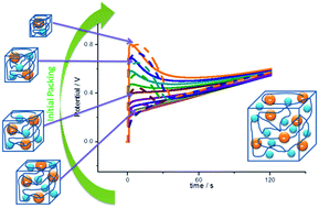
Reduced self-supported polypyrrole films have been oxidized by flow of a constant anodic current (galvanostatic experiments) in aqueous solution. The chronopotentiometric responses obtained from films reduced at high cathodic potentials present an initial peak attributed to the relaxation of packed conformational structures. This is a structural electrochemical response. The influence on this peak of the reduction potential, the electrolyte concentration or the anodic current was studied. The conformational relaxation model gives a good theoretical description of the experimental chronopotentiometric responses under the influence of the studied variables. The experimental evolution of the consumed electrical energy and the separation of the oxidation–relaxation and oxidation–diffusion components are also described by the theoretical model. The energy consumed during the oxidation reaction is a sensor of both the electrolyte concentration and the driving current, also described by the model.


Introduction

Biological processes are originated by chemical reactions in dense gels inside living cells. They involve conformational movements of the reactive macromolecules, changes of the intra and intermolecular interactions, solvent (water) and ionic exchanges.1 Conducting polymers can be considered as the simplest material model involving reactive polymeric chains, conformational movements, and solvent and ionic exchange, mimicking the intracellular matrix (ICM) of living cells, origin of the biological functions and life.2

For a conducting polymer exchanging anions and water with the electrolyte during reversible electrochemical reactions, the reaction can be summarized as:

 
(Pol0)s + n(A)sol + m(Solv) ⇄ [(Poln+)s(A)n(Solv)m]gel + n(e)metal (1)
where the sub-indexes mean: s, solid; sol, solution; Pol0 means the active centres on the polymeric chains (those points in the polymeric chains where a positive charge will be stored after oxidation); A are the anions required for charge balance; Solv are solvent molecules exchanged to keep osmotic and pressure balance forming, in the oxidized state, a biomimetic complex gel (polymeric chains, ions and solvent), indicated by the sub-index gel; e represents the electrons extracted during oxidation through the electrical contact. The polymeric electrode swells during oxidation and shrinks during reduction. Similar reactions using films of conducting polymers exchanging cations promote swelling during reduction and shrinking during oxidation.3–5

Chemical driven conformational movements of the conducting polymer chains have been included for their theoretical description of the results from the film electrochemical responses by the Electrochemically Stimulated Conformational Relaxation (ESCR) model.6–18 Those reaction induced conformational movements of chains generate, or destroy, the free volume required to lodge in, or expel from, the film charge balance counterions and osmotic balance solvent molecules. They constitute the basic molecular motors origin of the macroscopic structural variations of the film (swelling, shrinking, conformational compaction and conformational relaxation) and of different devices as polymeric artificial muscles,3,19–26 smart membranes with structural control of the transversal ionic mobility2,27–34 or faradaic drug storage and drug delivery of different counterions.35–42

Reaction (1) promotes the reduction under diffusion control of the counterions (through the oxidized and swollen film) towards the solution: the film shrinks and closes its structure still under a partial oxidized state. The reduction goes on after closing at high cathodic overpotentials, now under kinetic control of the slow conformational movements that allows the exit of the counterions through the rising conformational packed structure. The transition from the faster diffusion kinetic control to the slower conformational kinetic control of the reduction reaction is clearly visualized from coulovoltammetric responses.43 Any film after reduction and conformational compaction begins its oxidation by relaxation of the packed conformational structure starting by nucleation (visualized from electrochromic films) at those points of the film having a higher mobility of the chains.44,45 The influence of the conformational relaxation–nucleation on the electrochemical responses were known as anomalous results or material memory effect for many years in the literature.46–57 For conducting polymers exchanging cations during electrochemical reactions shrinking and conformational compaction processes occur during oxidation and the conformational relaxation, at the beginning of the film reduction.4,43

Voltammetric,13 coulovoltammetric16 or chronoamperometric7,58 responses from conformational compacted films of conducting polymers have been theoretically described by considering three basic components of the system (conducting polymer–solvent–ions) reaction energy:

- the energy variation of the system in absence of electric fields, ΔH;

- the energy for the conformational reduction–compaction of one mole of polymeric segments (zcηc, where zc is the charge consumed to compact one mole of polymeric chains and ηc is the applied overpotential related to the closing potential) and expulsion of the number of balancing ions defined (Faraday) by the consumed charge;

- and the energy required to relax during oxidation one mole of compacted polymeric segments (zrη, zr is the charge required to induce the reaction-relaxation of one mole of polymeric segments and η is the reaction overpotential) with entrance of the number of balancing ions defined by the consumed charge.

The attained physical–chemical equations also allow a good description of the influence of different variables (temperature,12 electrolyte concentration,16 ions present in solution,11 solvent,18 scan rate,15 applied potential14,15 or the reduction–compaction time59) on the structural electrochemical responses.

Reaction (1) opens an unprecedented possibility: any variable (mechanical, thermal, chemical) acting on the reaction rate will be sensed by the electrochemical response. Any device based on this reaction becomes a dual actuator–sensor. In previous papers we have developed a good theoretical description of the dual actuating–sensing properties of artificial muscles from its chronopotentiometric responses during swelling/shrinking by avoiding closing and conformational compaction processes.60–62

Here, the conformational model will be applied to describe the chronopotentiometric (potential versus time, E/t) responses from conformational reduced and packed polypyrrole (PPy) films when oxidized by flow of a constant anodic current. Whether the initially stable energetic states of conformational compaction keep, or not, the dual actuating–sensing properties will be also checked here. On this way a good theoretical description of the electrochemical responses under flow of constant currents from any multifunctional device (artificial muscles, batteries, supercapacitors, smart membranes, drug delivery, artificial chemical synapse, and so on) in particular, dual sensing–actuators, will be achieved.

Experimental

Experimental conditions, reactants and equipment used for the generation of the self-supported polypyrrole films on stainless steel electrodes have been described in previous papers.60,61

Once electrogenerated, the polypyrrole films were dried in air for 24 h and peeled off from the stainless steel electrode. The obtained self-supported PPy films (one by each side of the stainless steel electrode) were cut into smaller strips. A transversal paint (Max Effect, MAXFACTOR) strip close to the upper part avoids the contact by capillarity between the metal clamp and the electrolyte, allowing the electrical contact (above the paint strip) and limiting a well-defined PPy area and mass inside the electrolyte. The PPy film is immersed in the electrolyte up to the meniscus indicated by the transversal paint strip.

The experiments were performed in a 3 electrodes electrochemical cell (Fig 1a). The top of both, the steel counterelectrode (CE) and the polymer film working electrode (WE) were directly connected to the potentiostat–galvanostat by a metallic clamp. A computer using GPES electrochemical software recorded the electrochemical responses. The electrochemical behaviour was controlled in 0.5 M LiClO4 aqueous solution, by potential sweeps (20 consecutive cycles in order to get stationary voltammetric responses by erasing any previous material memory) between −0.5 and 0.5 V versus the reference electrode (Ag/AgCl 3 M KCl from Metrohm, every potential in this work is referred to this electrode) at 5 mV s−1. Fig. 1b shows the stationary voltammetric response. By its integration the coulovoltammetric response is attained (Fig. 1c) providing the reversible oxidation and reduction charge (maximum minus minimum).


image file: c4ra04530k-f1.tif
Fig. 1 (a) Experimental setup used for the electrochemical experiments: the PPy film working electrode (WE) and the stainless steel counter-electrode (CE) are connected (top, outside the electrolyte) to the potentiostat–galvanostat with a metal clamp, and Ag/AgCl reference electrode (RE). Electrochemical responses are recorded with a personal computer. (b) Stationary voltammetric result got from a polypyrrole film in 0.5 M LiClO4 aqueous solution between −0.5 and 0.5 V vs. Ag/AgCl at 5 mV s−1 and room temperature (24 °C). (c) Coulovoltammetric result attained by integration of figure (b).

Once the stationary oxidation–reduction response of the material is guaranteed the reproducible initial conformational state for each experiment is attained by submitting the PPy electrode to two potential steps every time: −0.5 V for 60 s, stepping then to 0.5 V for 60 s and then stepping to the cathodic potential of reduction and conformational compaction (usually −0.9 V), Fig. 2a, getting the chronoamperometric responses (Fig 2b). Then the flow of a constant current (usually 0.5 mA) was applied through the PPy electrode film during 100 s, Fig. 2c, keeping the oxidation charge around 75% of the voltammetric charge (from coulovoltammetric results), to get the experimental chronopotentiometric response (Fig. 2d). This experimental procedure was repeated by changing only one of the experimental variables, reduction potential, electrolyte concentration or oxidation current, every time. The influence of the applied current was studied for a constant oxidation charge (by changing the time of current flow) every time.


image file: c4ra04530k-f2.tif
Fig. 2 Experimental procedure followed to obtain the experimental responses: (a) in order to erase any previous structural memory, the self supported electrode was submitted a potential of −0.5 V for 60 s, then the potential was stepped to 0.5 V kept during 60 s and then the potential was stepped again to the reduction–compaction potential (usually −0.9 V) for 60 s. (b) Chronoamperometric responses to those potential steps. Finally, a constant current of 0.5 mA was applied (c) during 100 s to obtain the chronopotentiometric responses (d).

Mathematical treatment, simulations and integrals were performed employing Matlab R2008b software.

Model development

When a constant anodic current flows through a reduced conducting polymer electrode the evolution of the electrode potential with time, E(t), during its oxidation is described by a stair function:60
 
E(t) = ∑En(t)pn(t) (2)
where pn(t) is the unitary pulse function, taking a unitary value in the considered nth interval of time (required time to extract the nth electron from each of the film polymeric chains) and being zero outside this interval;63 being the evolution of the film potential during that time, En(t), measured in V:
 
image file: c4ra04530k-t1.tif(3)
with E0 the standard potential, ia is the constant applied current, Z (Ω) is the impedance of the electrochemical cell, n is the number of electrons extracted from the polymeric chains when a time t was elapsed during the experiment, ΔE (V) is the potential increment due to the extraction of a new electron from the polymeric chains during oxidation, R is the universal gas constant (R = 8.314 J K−1 mol−1), T is the temperature, α is the symmetry factor, F is the Faraday constant (F = 96[thin space (1/6-em)]485 C mol−1), V (dm3) is the volume of active conducting polymer, d is the reaction order related with [A], the concentration of anions in solution, e is the reaction order related to the concentration of active centres in the film, [Pol*], and ka0 is the oxidation pre-exponential factor.

So the potential evolution for the full oxidation of a conducting polymer film requiring the extraction of n consecutive electrons from each constitutive chain (assuming a monodisperse polymer) is formed, according with eqn (3) by n sloped steps.60

Eqn (3) is the multi sensing-actuating equation: it describes the quantitative dependence of the electrode potential evolution as a function of each of the experimental conditions: applied current, temperature, electrolyte concentration or mechanical conditions.62

However, eqn (3) does not include structural information related to the conformational compaction or conformational relaxation, swelling or shrinking processes.

Using as initial state a reduced and partially compacted conformational structure, the subsequent polymeric oxidation includes two components. First the oxidation initiates the conformational relaxation of the packed structure in order to allow the insertion of counterions and solvent consuming the relaxation charge, Qr (C). Then the oxidation–swelling is completed under diffusion kinetic control of the counterions through the swelling structure consuming the diffusion charge, Qd (C). So, the anodic chronoamperometric response (current, in A, versus elapsed time, in s) to a potential step is described by addition of the relaxation and diffusion components:14

 
image file: c4ra04530k-t2.tif(4)
where ir(t) is the current fraction employed to relax and open the polymeric structure in order to have enough free space to allow the subsequent penetration of balancing counterions and solvent; id(t) is the current consumed during oxidation–swelling completion under diffusion kinetic control of the counterions; iEDL(t) is the current employed to charge the electrical double layer; all currents measured in A, image file: c4ra04530k-t3.tif, with N0 the number of oxidation nuclei, λ (m) the length of an elemental polymeric chain, τ0 the pre-exponential factor of the relaxation time, A the area of the polymer film, ΔH the variation of the conformational energy in absence of electric field; Qr the charge consumed to relax and open the polymeric structure; b = 2D/h2 with D the diffusion coefficient and h the thickness of the polymeric film; Qd is the charge consumed during oxidation–swelling completion; i0 is the initial current; τ is the time constant.

Thus, by substituting eqn (4) into (3):

 
image file: c4ra04530k-t4.tif(5)
where Ez is the potential due to the cell impedance and Q = Qr + Qd + QEDL is the total consumed charge.

Here, Qr is supposed to be null if the applied cathodic potential is lower than the closing potential (considered as 0.55 V here64): neither the conformational compaction nor the subsequent relaxation occur because the relaxation is only present by oxidation of a compacted structure. Beyond the closing potential, the polymeric structure starts packing and the subsequent relaxation charge (Qr) follows an evolution with the applied oxidation–relaxation potential as shown in Fig. 3 by the red part.64


image file: c4ra04530k-f3.tif
Fig. 3 Coulovoltammogram (−900 mV to 300 mV at 50 mV s−1) obtained from a polypyrrole film coating a Pt electrode in 0.1 M NaCl. Numerical fitting (A = B + CED).

The evolution of the consumed relaxation charge fits the expression:

 
Qr (C) = k′ + k·Eφ = −0.51 + 0.051 × 10² (6)

The electrical energy consumed during current flow can be obtained by integration of the chronopotentiometric response (U = IE(t)dt65).

Results

Eqn (5) was checked employing the procedure indicated in the experimental part and Fig. 2.

Different packing states were attained by polarization at different cathodic potentials during the pre-treatment. After that, a constant anodic current of 1 mA was applied to the material getting the chronopotentiometric responses. Under similar conditions the theoretical chronopotentiometric responses were attained from eqn (2), using the same values of the constants from previous theoretical descriptions of electrochemical responses from PPy films.60–62 Experimental (full lines) and theoretical (dotted lines) results from rising conformational packed states attained by reduction at rising cathodic potentials, from −0.3 to −1.1 V for 60 s every time, are presented in Fig. 4.


image file: c4ra04530k-f4.tif
Fig. 4 Experimental and theoretical chronopotentiometric results obtained from a polypyrrole film in 0.5 M LiClO4 aqueous solution when two potential steps were performed before to the chronopotentiometric experiments: a potential of −0.5 V was applied for 60 s, then it was stepped to 0.5 V and kept during 60 s. After that, the potential was stepped again to different cathodic potentials, indicated in the figure, kept again during 60 s and then a constant current of 1 mA was applied during 100 s to obtain the chronopotentiometric results.

Both, experimental and theoretical results present a similar initial response. When the material reduction doesn't close the conformational structure (after reduction at −0.3 V) a continuous increase of the material potential is observed during the polymeric oxidation, as observed in previous works.60–62 For rising conformational packed initial states, attained after reduction at rising cathodic potentials from −0.6 V a potential peak is appreciated at the beginning of the anodic current flow. The potential achieved during the peak is higher for rising initial conformational packed states attained by reduction at more cathodic potentials. After the peak the potential drops trying to recover the potential evolution from a reduced and non-closed initial structure.

This behavior is quite similar to that observed by voltammetric responses: rising conformational packed structures constitute increasing energetic stable structures that behave as reaction resistances hindering the entrance of the balancing counterions from the solution. For the initial relaxation of rising packed structures higher electrochemical energies are required. Under constant temperature (thermal energy) and constant electrolyte concentration (chemical energy) the only energetic source working under constant current flow, Δ[i(A)E(V)], is the electrode overpotential. Thus, higher initial potentials are required, under flow of the same current, for the relaxation of rising packed conformational structures.

Once the relaxation of the packed conformations begins the energy required to go on with the material oxidation drops: the material potential also drops forming a maximum and the potential evolves towards those values described by the oxidation of a non-packed initial structure (after reduction at −0.3 V, Fig. 4). This evolution is faster for the theoretical description than for the experimental film due to the initial hypotheses of the material monodispersity (constituted by chains having the same chain length).

The electrical energy consumed during the experiments is the integral of the chronopotentiometric response, multiplied by the applied current [U = iE(t)dt65]. For different reduction or reduction–compaction potentials both, theoretical and experimental results show (Fig. 5) two linear evolutions of the consumed energy separated by the closing potential. The difference between both evolutions is the energy required to relax and open the polymeric structure.


image file: c4ra04530k-f5.tif
Fig. 5 Electrical energy consumed during the experiments shown in Fig. 4.

Bellow the closing potential, the consumed energy shows a slow increase with the cathodic potential applied during the film reduction: 15 and 3 mJ V−1 for experimental and theoretical results respectively. After reduction and conformational packing at higher cathodic potentials than the closing potential the relaxation–oxidation energy presents a higher slope: 36 and 26 mJ V−1 for experimental and theoretical results respectively.

As in previous studies, a linear evolution of the energy consumed for the film oxidation,66–68 after being reduced at lower cathodic potentials than the closing potential accounts for the electrochemical energy required to oxidize a rising reduced film. Beyond the closing potential the film oxidation energy includes two components: the linear increase of the film oxidation–diffusion energy goes on for a deep reduced film plus the linear increase of the oxidation–relaxation energy required for the initial relaxation of any packed conformational structure. After reduction at any potential more cathodic than the closing potential the difference between the extended linear part of the film oxidation–diffusion energy and the experimental energy is the energy consumed to relax, by oxidation, the packed conformational structure attained by reduction at the considered potential, Fig. 5. Results here presented for the two components of the film oxidation energy are parallel to those previously found for the two components of the reaction activation energy or of the molar conformational energy.66–68

The model was now checked for different electrolyte concentrations (Fig. 6a) or different applied anodic currents (Fig. 6b), keeping every time a constant value for the rest of the variables. The initial state of reduction and conformational packing was attained by reduction at −0.9 V for 60 s every time. Then the film was oxidized by consumption of the same anodic charge every time.


image file: c4ra04530k-f6.tif
Fig. 6 Experimental and theoretical chronopotentiometric responses obtained from a polypyrrole film in LiClO4 aqueous solution after pre-treatment every time at −0.5 V for 60 s, then it was oxidized at 0.5 V for 60 s and then reduced −0.9 V for 60 s. (a) In different LiClO4 concentrations, indicated in the figure, when a current of 1 mA was applied to the free-standing polypyrrole film; (b) in 0.5 M LiClO4 aqueous solution, applying different currents during different times consuming a constant charge of 70 mC.

In both cases, the evolutions of the experimental and theoretical results as a function of the studied variable are quite similar. For different electrolyte concentrations, the potential evolves at decreasing values when the concentration increases, as expected for any electrochemical reaction when the concentration of one of the reactants increases.61 However, the initial relaxation peak becomes sharper for a higher concentration, as expected form eqn (5).

By applying rising anodic currents to the initial reduced and packed polypyrrole electrode either one, the final potential, the slope of the chronopotentiometric response and the relaxation peak increase, as expected from eqn (5).

The electrical energy consumed during the chronopotentiometric responses to the galvanostatic film oxidation, follows a semilogarithmic relationship as a function of the electrolyte concentration (Fig. 7a), being the calibration curve U (mJ) = 101–15[thin space (1/6-em)]ln[A] and U (mJ) = 98–17[thin space (1/6-em)]ln[A] for experimental and theoretical results respectively. A linear relationship was attained between the consumed energy and the applied current (Fig. 7b) in accordance with previous results61 and the model (eqn (5)). The calibration curves were U (mJ) = 35 + 26i (mA) and U (mJ) = 39 + 25i (mA) for the experimental and theoretical results respectively.


image file: c4ra04530k-f7.tif
Fig. 7 Electrical energy consumed during chronopotentiometric experiments shown in Fig. 6a and 6b.

Conclusions

After reduction of self-supported polypyrrole films at high cathodic potentials in aqueous solutions the chronopotentiometric responses attained by oxidation under flow of anodic constant currents present an initial peak. This maximum was attributed to an initial reaction resistance due to the slow conformational relaxation process of the packed conformational reduced structure needed to relax the polymeric structure and to allow free diffusion of counterions and solvent through the polymeric film. This is a structural electrochemical response.

The observed peak of the experimental chronopotentiometric responses shifts to rising potentials after reduction of the polypyrrole film at rising cathodic potentials, by oxidation in decreasing electrolyte concentrations or by oxidation under flow of rising constant currents.

The electrochemically stimulated conformational relaxation model allows a good theoretical description of the structural chronopotentiograms under influence of the studied experimental variables. The applied constant anodic current is consumed for the three components of the oxidation reaction: conformational relaxation and opening of the structure, oxidation–swelling under diffusion kinetic control of the counterions from the solution through the swollen film and charge of the electrical double layer.

The electrical energy consumed during the oxidation process gives, as a function of the reduction–compaction potential, two different linear variations (two slopes) allowing a good quantification of the two components of the reaction: oxidation–diffusion and oxidation–relaxation.

Moreover the presence of the structural reduction–compaction and subsequent relaxations the film reaction keeps its sensing abilities, by the consumed oxidation energy, of the experimental variables: electrolyte concentration and applied constant current. The theoretical model also describes the sensing property of the reaction.

Acknowledgements

Authors acknowledge financial support from Spanish Government (MCI) Project MAT2011-24973, and to ESNAM, the European Scientific Network for Artificial Muscles (COST Action MP1003). J.G. Martinez acknowledges Spanish Education Ministry for a FPU grant (AP2010-3460).

Notes and references

  1. L. Stryer, Biochemistry, W.H. Freeman and Company, New York, 1995 Search PubMed.
  2. T. F. Otero and J. G. Martinez, J. Mater. Chem. B, 2013, 1, 26–38 RSC.
  3. T. F. Otero, J. G. Martinez and J. Arias-Pardilla, Electrochim. Acta, 2012, 84, 112–128 CrossRef CAS PubMed.
  4. L. V. Conzuelo, J. Arias-Pardilla, J. V. Cauich-Rodríguez, M. A. Smit and T. F. Otero, Sensors, 2010, 10, 2638–2674 CrossRef CAS PubMed.
  5. T. F. Otero and M. T. Cortes, Chem. Commun., 2004, 284–285 RSC.
  6. T. Otero and E. Angulo, Solid State Ion., 1993, 63–65, 803–809 CrossRef CAS.
  7. T. Otero, H. Grande and J. Rodriguez, J. Electroanal. Chem., 1995, 394, 211–216 CrossRef.
  8. T. F. Otero, H. Grande and J. Rodriguez, Synth. Met., 1996, 76, 293–295 CrossRef CAS.
  9. T. F. Otero, H. Grande and J. Rodriguez, Synth. Met., 1996, 76, 285–288 CrossRef CAS.
  10. T. F. Otero, H. Grande and J. Rodriguez, Electrochim. Acta, 1996, 41, 1863–1869 CrossRef CAS.
  11. T. F. Otero, H. Grande and J. Rodriguez, Synth. Met., 1996, 83, 205–208 CrossRef CAS.
  12. T. F. Otero and H. Grande, J. Electroanal. Chem., 1996, 414, 171–176 Search PubMed.
  13. T. F. Otero, H. Grande and J. Rodriguez, Synth. Met., 1997, 85, 1077–1078 CrossRef CAS.
  14. T. F. Otero, H. J. Grande and J. Rodriguez, J. Phys. Chem. B, 1997, 101, 3688–3697 CrossRef CAS.
  15. T. F. Otero, H. Grande and J. Rodriguez, J. Phys. Chem. B, 1997, 101, 8525–8533 CrossRef CAS.
  16. H. Grande and T. F. Otero, J. Phys. Chem. B, 1998, 102, 7535–7540 CrossRef CAS.
  17. H. Grande and T. F. Otero, Electrochim. Acta, 1999, 44, 1893–1900 CrossRef CAS.
  18. H. Grande, T. F. Otero and I. Cantero, J. Non-Cryst. Solids, 1998, 235, 619–622 CrossRef.
  19. T. F. Otero, E. Angulo, J. Rodríguez and C. Santamaría, J. Electroanal. Chem., 1992, 341, 369–375 CrossRef CAS.
  20. Q. Pei and O. Inganas, J. Phys. Chem., 1992, 96, 10507–10514 CrossRef CAS.
  21. E. Smela, Adv. Mater., 2003, 15, 481–494 CrossRef CAS.
  22. E. W. H. Jager, E. Smela and O. Inganas, Science, 2000, 290, 1540–1545 CrossRef CAS.
  23. B. Jeong and A. Gutowska, Trends Biotechnol., 2002, 20, 305–311 CrossRef CAS.
  24. M. Shahinpoor, Y. Bar-Cohen, J. O. Simpson and J. Smith, Smart Mater. Struct., 1998, 7, R15–R30 CrossRef CAS.
  25. P. Brochu and Q. Pei, Macromol. Rapid Commun., 2010, 31, 10–36 CrossRef CAS PubMed.
  26. T. Mirfakhrai, J. D. W. Madden and R. H. Baughman, Mater. Today, 2007, 10, 30–38 CrossRef CAS.
  27. M. J. Ariza and T. F. Otero, J. Membr. Sci., 2007, 290, 241–249 CrossRef CAS PubMed.
  28. J. Pellegrino, Ann. N. Y. Acad. Sci., 2003, 984, 289–305 CrossRef CAS PubMed.
  29. P. Burgmayer and R. Murray, J. Am. Chem. Soc., 1982, 104, 6139–6140 CrossRef CAS.
  30. M. N. Akieh, A. Varga, R.-M. Latonen, S. F. Ralph, J. Bobacka and A. Ivaska, Electrochim. Acta, 2011, 56, 3507–3515 CrossRef CAS PubMed.
  31. M. J. Ariza and T. F. Otero, Colloids Surf., A, 2005, 270–271, 226–231 CrossRef CAS PubMed.
  32. P. Burgmayer and R. Murray, J. Phys. Chem., 1984, 88, 2515–2521 CrossRef CAS.
  33. W. E. Price, C. O. Too, G. G. Wallace and D. Zhou, Synth. Met., 1999, 102, 1338–1341 CrossRef CAS.
  34. C. Weidlich and K.-M. Mangold, Electrochim. Acta, 2011, 56, 3481–3484 CrossRef CAS PubMed.
  35. D. Svirskis, B. E. Wright, J. Travas-Sejdic, A. Rodgers and S. Garg, Sens. Actuators, B, 2010, 151, 97–102 CrossRef CAS PubMed.
  36. M. R. Abidian, D. H. Kim and D. C. Martin, Adv. Mater., 2006, 18, 405–408 CrossRef CAS PubMed.
  37. D. Svirskis, J. Travas-Sejdic, A. Rodgers and S. Garg, J. Controlled Release, 2010, 146, 6–15 CrossRef CAS PubMed.
  38. R. T. Richardson, A. K. Wise, B. C. Thompson, B. O. Flynn, P. J. Atkinson, N. J. Fretwell, J. B. Fallon, G. G. Wallace, R. K. Shepherd and G. M. Clark, Biomaterials, 2009, 30, 2614–2624 CrossRef CAS PubMed.
  39. A. Guiseppi-Elie, Biomaterials, 2010, 31, 2701–2716 CrossRef CAS PubMed.
  40. S. Geetha, C. R. K. Rao, M. Vijayan and D. C. Trivedi, Anal. Chim. Acta, 2006, 568, 119–125 CrossRef CAS PubMed.
  41. A. A. Entezami and B. Massoumi, Iran. Polym. J., 2006, 15, 13–30 CAS.
  42. G. W. Wang, Y. N. Lu, L. P. Wang, H. J. Wang and J. Y. Wang, J. Nanosci. Nanotechnol., 2014, 14, 596–612 CrossRef CAS PubMed.
  43. T. F. Otero, J. G. Martinez, M. Fuchiwaki and L. Valero, Adv. Funct. Mater., 2014, 24, 1265–1274 CrossRef CAS.
  44. T. Otero, I. Boyano, M. Cortes and G. Vazquez, Electrochim. Acta, 2004, 49, 3719–3726 CrossRef CAS PubMed.
  45. T. F. Otero and I. Boyano, ChemPhysChem, 2003, 4, 868–872 CrossRef CAS PubMed.
  46. J. Heinze and A. Rasche, J. Solid State Electrochem., 2006, 10, 148–156 CrossRef CAS.
  47. T. Sendai, H. Suematsu and K. Kaneto, Jpn. J. Appl. Phys., 2009, 48, 051506 CrossRef.
  48. B. Villeret and M. Nechtschein, Phys. Rev. Lett., 1989, 63, 1285–1287 CrossRef CAS.
  49. M. A. Vorotyntsev, M. Skompska, E. Pousson, J. Goux and C. Moise, J. Electroanal. Chem., 2003, 552, 307–317 CrossRef CAS.
  50. G. Inzelt, R. Day, J. Kinstle and J. Chambers, J. Phys. Chem., 1983, 87, 4592–4598 CrossRef CAS.
  51. K. Aoki, J. Electroanal. Chem., 1994, 373, 67–73 CrossRef CAS.
  52. G. Inzelt, G. Horanyi and J. Chambers, Electrochim. Acta, 1987, 32, 757–763 CrossRef CAS.
  53. C. Barbero, R. Kotz, M. Kalaji, L. Nyholm and L. Peter, Synth. Met., 1993, 55, 1545–1551 CrossRef CAS.
  54. C. Odin and M. Nechtschein, Synth. Met., 1991, 44, 177–188 CrossRef CAS.
  55. M. Lapkowski, M. Zagorska, I. Kulszewiczbajer and A. Pron, Synth. Met., 1993, 55, 1570–1573 CrossRef CAS.
  56. M. Laridjani, J. Pouget, E. Scherr, A. Macdiarmid, M. Jozefowicz and A. Epstein, Macromolecules, 1992, 25, 4106–4113 CrossRef CAS.
  57. L. Goldenberg, S. Aeiyach and P. Lacaze, Synth. Met., 1993, 55, 1365–1370 CrossRef CAS.
  58. B. J. West, T. F. Otero, B. Shapiro and E. Smela, J. Phys. Chem. B, 2009, 113, 1277–1293 CrossRef CAS PubMed.
  59. T. F. Otero and R. Abadias, J. Electroanal. Chem., 2008, 618, 39–44 CrossRef CAS PubMed.
  60. T. F. Otero, J. J. Sanchez and J. G. Martinez, J. Phys. Chem. B, 2012, 116, 5279–5290 CrossRef CAS PubMed.
  61. J. G. Martinez and T. F. Otero, J. Phys. Chem. B, 2012, 116, 9223–9230 CrossRef CAS PubMed.
  62. J. G. Martinez and T. F. Otero, Sens. Actuators, B, 2014, 195, 365–372 CrossRef CAS PubMed.
  63. Handbook of mathematical functions with formulas, graphs, and mathematical tables, ed. M. Abramowitz and I. A. Stegun, Dover, New York, 1964 Search PubMed.
  64. T. F. Otero, M. Alfaro, V. Martinez, M. A. Perez and J. G. Martinez, Adv. Funct. Mater., 2013, 23, 3929–3940 CrossRef CAS.
  65. H. W. Beaty and D. G. Fink, Standard handbook for electrical engineers, McGraw-Hill, New York, 16th edn, 2013 Search PubMed.
  66. T. F. Otero and J. G. Martinez, Adv. Funct. Mater., 2013, 23, 404–416 CrossRef CAS.
  67. T. F. Otero and M. Caballero Romero, Polym. Int., 2010, 59, 329–336 CrossRef CAS.
  68. T. F. Otero and J. M. Garcia de Otazo, Synth. Met., 2009, 159, 681–688 CrossRef CAS PubMed.

This journal is © The Royal Society of Chemistry 2014