Retracted Article: Investigation on corrosion protection and mechanical performance of minerals substituted hydroxyapatite coating on HELCDEB-treated titanium using pulsed electrodeposition method
D. Gopi*ab,
A. Karthikaa,
D. Rajeswariac,
L. Kavithac,
R. Pramodd and
Jishnu Dwivedid
aDepartment of Chemistry, Periyar University, Salem 636011, India. E-mail: dhanaraj_gopi@yahoo.com; Fax: +91-427-2345124; Tel: +91-427-2345766
bCentre for Nanoscience and Nanotechnology, Periyar University, Salem 636011, India
cDepartment of Physics, School of Basic and Applied Sciences, Central University of Tamilnadu, Thiruvarur 610101, India
dIndustrial Accelerator Section, Raja Ramanna Centre for Advanced Technology, Indore 452013, India
First published on 23rd July 2014
Abstract
The present work aims to investigate the effects of minerals (strontium, magnesium and zinc) substituted hydroxyapatite (M-HAP) coating on high-energy low-current DC electron beam (HELCDEB)-treated titanium (Ti). The M-HAP coating was developed over the untreated and HELCDEB-treated Ti by pulsed electrodeposition, and was characterized by scanning electron microscopy, X-ray diffraction, Fourier transform infrared spectroscopy, Raman spectroscopy, X-ray photoelectron spectroscopy and electrochemical techniques. The M-HAP coating was obtained on Ti treated at 500 and 700 keV HELCDEB. The coating on the 700 keV HELCDEB-treated Ti showed better corrosion resistance properties than the coating obtained on the 500 keV HELCDEB-treated and untreated Ti. The M-HAP coating on the HELCDEB-treated Ti showed typical flower-like morphology, and exhibited better resistance to corrosion in simulated body fluid (SBF), along with increased microhardness and decreased contact angle. An in vitro study of the coating was conducted by immersion in the SBF solution for 1–7 days. The results clearly showed that the M-HAP coating on 700 keV HELCDEB-treated Ti enhanced its corrosion resistivity and mechanical properties. The coating may have many applications in orthopedics because it could improve implant fixation in human bone.
1. Introduction
The development of biocompatible implant material is one of the most important research areas in medical science. Metallic implants, such as Ti and its alloys, have gained significant attention in the field of orthopedic and dental prostheses. However, due to their bioinertness,1 the contact between these implants and bone tissue is solely a mechanical connection. Furthermore, their direct implantation into the human body can cause many problems, including low strength connections with bone, poor bioactivity, long curing time and metallic ions migrating into the body in physiological environments.2 Hence, metallic implants are coated with osteoconductive bioceramics, especially HAP [Ca10(PO4)6(OH)2]. HAP can develop a tight bond with bone tissue, which is stable towards bioresorption and has no adverse effects on the human body.3 The natural HAP present in bone contains different elements, which play a key role in bone formation and the normal function of bone tissue. Synthetic HAP can undergo metal ion substitution and a small quantity of these ions improves its performance in clinical applications. Of the many mineral ions,4,5 strontium (Sr), magnesium (Mg) and zinc (Zn) have recently attracted great interest.Sr is an important trace element in the human body and a low dose of Sr diminishes the risk of fractures in postmenopausal osteoporotic patients.6 In addition to promoting bone formation, Sr favors bone healing.7,8 Sr has been shown to enhance preosteoblast proliferation and decrease bone resorption by inhibiting osteoclast resorbing activity and osteoclastic differentiation.8 Many reports have shown that Sr-HAP enhances the bioactivity and biocompatibility of HAP by the release of Sr2+ ions,9–11 and also improves its mechanical properties.12
Similarly, Mg is essential for bone metabolism, because the depletion of Mg adversely affects skeletal metabolism and causes the cessation of bone growth.13,14 Mg is the fourth most abundant cation in the human body and is thought to interact with osteoblast integrins, which are responsible for cell adhesion and stability.15,16 Zn occurs naturally in human bone and has roles in enzyme regulation, cell division and bone formation, which is strongly associated with the growth, development, and maintenance of healthy bones.17 Zn has antibacterial activity, thus it minimizes the bacterial load on the implant surface after orthopedic implantation18 and improves the mechanical strength.19 Bone growth impediment and defects are commonly observed in humans and animals because of Zn deficiency.20,21 Zinc has been reported to have a stimulatory effect on bone formation and mineralization.22 Recently, our research group has reported the synthesis of minerals (Sr, Mg and Zn) substituted HAP with improved bioactivity23 and also the development of Sr- and Mg-substituted HAP coating on polymer protected 316L SS for improved biocompatibility.24 In addition, Gopi et al. reported the development of CNT/CMC/M-HAP composite and its biological activity on HOS MG63 osteoblast cells.25 Furthermore, Aina et al. investigated the effect of the addition of Sr and Mg ions to the HAP structure on its physico-chemical properties.26 Cox et al. performed a live/dead assay using the MC3T3 osteoblast precursor cells against the as-synthesized Sr, Mg, and Zn-substituted HAP.27
An important requirement of a bioceramic coating is its good adhesion to the implant material. In order to obtain an adhesive coating with enhanced corrosion resistance, and to achieve better osseointegrated implants, the surface of the titanium is usually modified. This can induce new bone growth on the implant.
The surface properties of bioimplant materials, such as surface roughness and wettability, play an essential role in bonding with living cells.28 Many surface modification techniques are used to modify the surface of implants, including chemical etching, alkaline heat treatment, laser, microwave, and electron beam irradiation, and plasma and ion beam irradiation/implantation.29 In particular, electron beam treatment has been proven to be an efficient method for the surface modification of metallic materials.30 Energetic electron beam treatments improve the microhardness and corrosion resistance of the implants. Dong et al.29 and Proskurovsky et al.31 have reported that pulsed electron beam treatment improved the physical, chemical and mechanical properties of the metal, which may be because of the metastable states in the surface layers of the metal. This technique has several advantages, such as protecting the surface of the implant from oxidation, forming a strong bond between the substrate and the melted surface, and preventing cracks and pores in the surface of the implant.32 Recently Gopi et al.32,33 developed HAP and Sr-HAP coating with a flower-like morphology on HELCDEB-treated Ti and 316L stainless steel by pulsed electrodeposition and electrodeposition, respectively. During HELCDEB irradiation, the surface undergoes superfast heating, melting and solidification to provide improved physicochemical properties and bonding strength to the material, which cannot be achieved with other surface treatments.33
Many methods have been developed to obtain bioactive pure and substituted HAP coatings, such as biomimetic processes,34,35 pulsed laser deposition,36 electrochemical deposition,37–40 micro arc oxidation,41 and plasma spraying.42 Electrodeposition can be used to deposit HAP on any complex geometry substrates. However, in this method, H2O is reduced to OH− and large amounts of H2 are produced. The H2 gas prevents the nucleation and growth of HAP on the metallic surface, which results a loose, porous coating with low adhesion.43 However, pulsed electrodeposition has advantages including higher deposition rate, control of deposition composition, improved coating quality with the desired structure, and regulation of the coating thickness. During pulsed electrodeposition, hydrogen peroxide (H2O2) inclusion in the electrolyte restricts the evolution of H2 bubbles, which enhances the ionic mobility and allows the deposition of mineral ions on the implant material.44,45
The present work aims to study the effect of the M-HAP coating obtained on HELCDEB-treated Ti under different irradiation conditions. The corrosion resistive performance and mechanical properties of the M-HAP coating on HELCDEB-treated Ti were evaluated. Along with this, the in vitro dissolution of the M-HAP coating was examined in simulated body fluid (SBF) in order study the reactivity and reliability of the M-HAP coating.
2. Experimental
2.1. Preparation of Ti substrate
Pieces of pure Ti metal (99.99%) with a size of 10 × 10 × 3 mm were used as the substrates for the pulsed electrodeposition. The substrates were abraded using 400–1200 grit silicon carbide sheets and subsequently polished with 1.5 μm diamond paste. In between polishing and after polishing, the substrates were washed and ultrasonically cleaned with acetone to prevent the cross contamination of abrasive particles.2.2. High-energy low-current DC electron beam treatment on Ti
The specimens were surface treated using a 700 keV DC accelerator with an electron beam with a current of 1.5 mA at an energy of 500 or 700 keV to enhance the mechanical properties and corrosion resistance of the Ti metal. The procedure of the irradiation process was followed as per our previous report.332.3. Preparation and pulsed electrodeposition of M-HAP
Analytical grade 0.294 M Ca(NO3)2·2H2O, 0.042 M Sr(NO3)2·6H2O, 0.042 M Mg(NO3)2·6H2O and 0.042 M Zn(NO3)2 were dissolved in deionized water and 0.25 M (NH4)2HPO4 was prepared separately. Then, the phosphate ion solution was added dropwise to the cationic solution keeping the target ratio of (Ca + Sr + Mg + Zn)/P as 1.67. The electrolyte was deaerated with N2 for 30 min and the pH of the electrolyte was adjusted to 4.5 using NH4OH. The electrolyte temperature was maintained at 65 °C using a thermostat, and a magnetic stirrer was used to keep the concentration of the electrolyte uniform at a speed of 180 rpm. Prior to starting the coating procedure, hydrogen peroxide (2000 ppm) was added to the electrolyte solution in order to decrease the hydrogen gas evolution.33Pulsed electrodeposition was carried out in a regular three electrode system using an electrochemical workstation (CHI 760C, CH Instruments, USA) in which the untreated Ti and HELCDEB treated Ti specimens acted as working electrode. A platinum electrode and a saturated calomel electrode (SCE) were used as counter and reference electrodes, respectively. The deposition was performed for 1 h on untreated and surface-irradiated Ti samples in galvanostatic mode with a constant current density of 1.0 mA cm−2. The pulse on and off time was kept constant as per our previous study,33 and the optimum conditions were 1 s pulse on time and 4 s pulse off time for current densities of 1.0 and 0 mA cm−2. After the coating process, the specimens were removed from the electrolyte and washed with deionized water, then dried in a desiccator for 4 h.
2.4. Structural characterizations
The FT-IR spectra were obtained using a Perkin Elmer RX1 FT-IR spectrometer and were recorded in the 4000–400 cm−1 region with 4 cm−1 resolution by using KBr pellet technique. The Raman spectra of M-HAP coatings were obtained with a Raman spectrometer (Horiba-Jobin, LabRAM HR) with the scan range of 50–3000 cm−1. All the spectra were recorded at ambient temperature.The X-ray diffraction (XRD) patterns of the pure Ti, pure HAP, and as-coated samples were obtained using a PANalytical X'Pert PRO diffractometer in the range 20° ≤ 2θ ≤ 60° with Cu Kα radiation (1.5406 Å).
The surface morphology and actual composition of the as-deposited samples were observed by high-resolution scanning electron microscopy (HRSEM, JSM 840A Scanning microscope, JEOL – Japan) equipped with energy dispersive X-ray analysis (EDAX). Cross-sectional HRSEM analysis of all the coated samples was also carried out. The average thickness of each coating was obtained from three measurements at different positions.
X-ray photoelectron spectroscopy (XPS; Omicron Nano-Technology instrument) with a focused monochromatic Al Kα source (1486.6 eV) for excitation was used for chemical composition analysis of the M-HAP coating. The electron take off angle was 54.7° and the XPS survey spectrum over a binding energy range of 0–1100 eV was acquired with an analyzer pass energy of 50 and 20 eV for high-resolution elemental scans. The vacuum pressure was around 3.5 × 10⁻¹⁰ mbar during spectral acquisition. Data analysis was carried out with EIS-Sphera software provided by the manufacturer.25
2.5. Contact angle measurements
The contact angle measurement of the untreated, 500 and 700 keV HELCDEB-treated Ti specimens were analyzed using a video-based contact angle meter (OCA 15EC, Data Physics Instruments, Germany). An equal volume of distilled water was placed on every sample with a micropipette, forming a drop or spreading on the surface. Photos were taken throughout to record the shape of the drops and the contact angle was measured. Five measurements were taken at different locations on each specimen and an average contact angle was calculated.2.6. Mechanical properties of the M-HAP coating
2.7. Electrochemical characterizations
The potentiodynamic polarization study was performed on the untreated, HELCDEB-treated and M-HAP coatings on the untreated and HELCDEB treated Ti samples using the electrochemical workstation (CHI 760C, USA) in SBF solution. These Ti samples with an exposed surface area of 1 cm2 were used as the working electrode. The SBF solution was prepared at pH 7.4 and the temperature was kept at 37 °C.47 Potentiodynamic polarization studies were performed in a potential range of −1 to 1 V at a scan rate of 0.001 V s−1. The potentiodynamic polarization was repeated at least three times in order to obtain average values.2.8. Inductively coupled plasma atomic emission spectroscopy
The SBF dissolution study of the M-HAP coating was performed by inductively coupled plasma-atomic emission spectroscopy (ICP-AES, Thermo Electron IRIS INTREPID II XSP DUO, USA). The fresh SBF was maintained by immersing the coated specimen for 1, 4 and 7 days.3. Results and discussion
3.1. Functional group analysis
The FT-IR spectra of the M-HAP coating on untreated Ti, and 500 and 700 keV HELCDEB-treated Ti are given in Fig. 1(a)–(c). The characteristic peaks observed at 480.89 (ν2), 563.00 and 601.34 (ν4), 977.89 (ν1), 1028.75 and 1098.26 (ν3) cm−1 correspond to the PO34− group. The peaks at 3427.87 and 1642.93 cm−1 were assigned to the stretching and bending mode of the adsorbed water. Moreover, the characteristic –OH peaks of HAP at around 3569.41 and 633.12 cm−1 correspond to the stretching and bending modes.48 Thus, the FT-IR spectra confirmed the formation of the M-HAP coating by pulsed electrodeposition and no other impurities were identified. | ||
| Fig. 1 FT-IR spectra of the M-HAP coating on (a) untreated Ti, (b) 500 keV HELCDEB-treated Ti and (c) 700 keV HELCDEB treated Ti. | ||
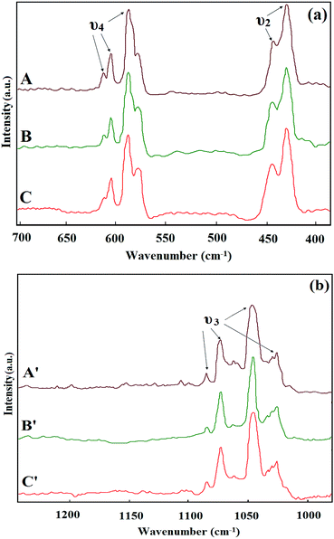
The Raman spectra of the M-HAP coatings that contain bands arising from the four phosphate internal vibration modes are shown in Fig. 2(a) and (b). The bands for the stretching and librational modes of the hydroxyl ions are weak and provide little information on the mineral environment in the Raman spectrum.49 Therefore, we focused on the phosphate modes. The most intense bands at 964 cm−1 are caused by the symmetric ν1 (PO4) stretching mode of the free tetrahedral phosphate ion. The ν1 (PO4), ν2 (PO4) bands at 447 and 432 cm−1, the ν3 (PO4) bands at 1082, 1073, 1047, and 1026 cm−1, and the ν4 (PO4) bands at 611, 603, and 587 cm−1 were assigned (Fig. 2(a) and (b)). The Raman spectra of the M-HAP coating contain the typical stretching frequency of the phosphate ion, which confirms the presence of the calcium phosphate phase. No other additional bands were observed and this confirms the absence of impurities, which is consistent with the FT-IR results.
3.2. Diffraction studies
The XRD patterns of the Ti substrate, the pure HAP coating on untreated Ti, and the M-HAP coating on untreated Ti, and 500 and 700 keV HELCDEB-treated Ti are shown in Fig. 3(a)–(e). The XRD pattern of pure Ti showed no diffraction peaks apart from the Ti peak (Fig. 3(a)). The pattern in Fig. 3(c) is less intense and showed a slight shift compared with that of pure HAP (Fig. 3(b)), which agrees well with ICDD no. 09-0432.33 In this regard, the main diffraction peaks of HAP obtained at 25.9°, 31.7°, 32.2° and 32.9° are shifted to the left by the substitution of mineral ions because of the expansion and contraction in the HAP lattices26,50,51. Fig. 3(d) and (e) show the intense peaks for the M-HAP coating obtained on 500 and 700 keV HELCDEB-treated Ti, which indicated that the crystallinity of the coating is high. These patterns reveal the presence of Sr, Mg and Zn in the M-HAP coating.48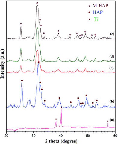 | ||
| Fig. 3 XRD pattern of (a) the pure Ti substrate, (b) the HAP coating on untreated Ti, and the M-HAP coating on (c) untreated Ti, (d) 500 keV HELCDEB-treated Ti and (e) 700 keV HELCDEB-treated Ti. | ||
3.3. Morphological studies
The SEM images of untreated, 500 and 700 keV HELCDEB-treated Ti, and M-HAP coatings on the Ti metal before and after HELCDEB treatments are displayed in Fig. 4(a)–(f). The morphology of the polished Ti is shown in Fig. 4(a). The M-HAP coating on the untreated Ti exhibits spherical morphology at 1 s pulse on time and 4 s pulse off time (Fig. 4(b)). The modified surface of the 500 and 700 keV HELCDEB-treated Ti specimens are shown in Fig. 4(d) and (g), respectively, and consist of the homogeneous micro-structured eruptions formed during the rapid solidification of the surface melted layer. The magnified views of the surface-treated Ti are given as insets in Fig. 4(d) and (g). A uniformly arranged flower-like coating (Fig. 4(e)) which covers the entire surface was observed for the 500 keV HELCDEB-treated Ti substrate. The flower-like structure may have originated from the centre of the erupted spot, which had a diameter of few micrometers (∼8 μm), shown in the inset in Fig. 4(e). Fig. 4(h) also shows the formation of a flower-like M-HAP coating over the 700 keV HELCDEB-treated Ti. The magnified image also had a flower-like structure (inset in Fig. 4(h)). Hence, the morphological studies clearly show that the surface treatment played a major role in the formation and uniformity of the flower-like structure of the M-HAP coating. Fig. 4(c), (f) and (i) shows the cross-sectional view of the as-developed coatings. The thickness of the M-HAP coating on untreated Ti (Fig. 3(c)), 500 keV HELCDEB-treated Ti (Fig. 3(f)) and 700 keV HELCDEB-treated Ti (Fig. 3(i)) ranged from 27–29 μm.The Fig. 4(j) shows the EDAX spectrum of the M-HAP coating on the HELCDEB-treated Ti. The distribution of Sr, Mg, Zn, Ca, P and O ions is shown in Fig. 4(j) and supports the presence of the mineral ions in the surface-treated Ti. Furthermore, the quantitative measurement of the M-HAP coating is shown in the inset in Fig. 4(j).
3.4. X-ray photoelectron spectroscopic study
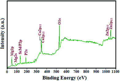
XPS is a widely used surface analytical technique that is useful for detecting the elements present in a material. The XPS survey spectrum of the M-HAP coating on 700 keV HELCDEB-treated Ti is shown in Fig. 5. The survey spectrum identified Ca, P, Sr, Mg, Zn, and O as the major constituents of the M-HAP coating on the 700 keV HELCDEB-treated Ti substrate. The observed peaks near 347.5 and 350.7 eV are attributed to Ca 2p3/2 and Ca 2p1/2, respectively.52 The binding energy of P 2s is 190.2 eV and the peak at 133.2 eV is the overlap of the Sr 3d and P 2p peaks, because the Sr 3d5/2 (133 ± 0.5 eV) and the P 2p (132–133 eV) lines were located close to the Sr peak.53 The O 1s peak observed with a binding energy of 530.8 and 532.2 eV are attributed to oxygen associated with the phosphate group and adsorbed water in the M-HAP, respectively.54 The peak at 49.9 eV is attributed to Mg and the typical binding energy of Zn 2p is 1022.0 eV.55 Therefore, the XPS data clearly indicates the presence of minerals that confirms the formation of M-HAP.253.5. Contact angle measurements
The contact angle between the deionized water and 500 keV HELCDEB-treated Ti was 53.09°, whereas that for 700 keV HELCDEB-treated Ti was 49.05° (Fig. 6(b) and (c)). These contact angles suggested that the hydrophobic surface of untreated Ti (75.70°) (Fig. 6a) becomes hydrophilic after treatment. | ||
| Fig. 6 Contact angle measurement of (a) untreated Ti, (b) 500 keV HELCDEB-treated Ti and (c) 700 keV HELCDEB-treated Ti. | ||
3.6. Adhesion strength
Fig. 7 summarizes the adhesion strength of the M-HAP coating on untreated Ti, and 500 and 700 keV HELCDEB-treated Ti. The adhesion strength of the M-HAP coating on untreated Ti was measured as 20.4 ± 1.3 MPa. The M-HAP coating on 700 keV HELCDEB-treated Ti exhibits a slightly higher adhesion strength (22.1 ± 1.1 MPa) than that of the coating obtained on 500 keV HELCDEB-treated Ti (21.6 ± 0.7 MPa). These results fulfill the main requirement of the coating for the prolonged life of the implant.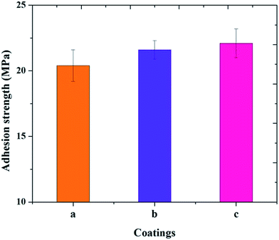 | ||
| Fig. 7 Adhesion strength measurements of the M-HAP coating on (a) untreated Ti, (b) 500 keV HELCDEB-treated Ti and (c) 700 keV HELCDEB-treated Ti. | ||
3.7. Vickers microhardness
The results of the microhardness for the M-HAP coatings on untreated Ti, and M-HAP coatings on 500 and 700 keV HELCDEB-treated Ti are shown in Fig. 8. The microhardness is greater for the M-HAP coating on HELCDEB-treated Ti samples compared with the coating on untreated Ti (6.31 ± 0.42 GPa). The M-HAP coating on the 700 keV HELCDEB-treated Ti sample (7.16 ± 0.6 GPa) exhibits a slightly higher hardness value than the 500 keV HELCDEB-treated sample (7.02 ± 0.35 GPa). This indicates that the as-formed coating remained intact on the HELCDEB-treated Ti substrate.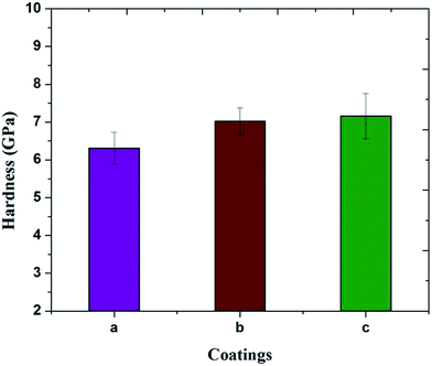 | ||
| Fig. 8 Vickers microhardness measurements of the M-HAP coating on (a) untreated Ti, (b) 500 keV HELCDEB-treated Ti and (c) 700 keV HELCDEB-treated Ti. | ||
3.8. Potentiodynamic polarization studies
Representative potentiodynamic polarization curves of the untreated Ti, and 500 and 700 keV HELCDEB-treated Ti, and M-HAP coatings on the untreated Ti, and 500 and 700 keV HELCDEB-treated Ti are shown in Fig. 9. The values of Ecorr and Icorr for the untreated Ti were −0.57 V and 0.54 μA cm−2, for the 500 keV HELCDEB-treated Ti they were −0.148 V and 0.09 μA cm−2, and for the 700 keV HELCDEB-treated Ti they were −0.09 V and 0.08 μA cm−2, respectively. The surface treated samples showed higher Ecorr and Icorr values than the untreated Ti sample. For the samples coated with M-HAP, the Ecorr values were −0.023, 0.088, and 0.245 V, whereas the corresponding Icorr values were 0.42, 0.34, and 0.22 μA cm−2, respectively. The Ecorr values for the coated samples were higher than that of the untreated Ti sample, which indicates the passive nature of the coatings. Compared with the M-HAP coating on untreated Ti, the Ecorr and Icorr values of the M-HAP coating on HELCDEB-treated Ti specimens showed better shift towards the nobler direction. In particular, the M-HAP coating on 700 keV HELCDEB-treated Ti showed a larger positive shift than the M-HAP coating on the 500 keV HELCDEB-treated Ti.3.9. SBF dissolution study
ICP-AES analysis showed that the dissolution of mineral ions occurred from the M-HAP coating during the first day. The average Ca ion concentration in the solution increased rapidly from ∼1.2 to ∼26.9 ppm, which is the difference between the control value and leach out value, from 0 to 1 day. Likewise, the release of Sr, Mg, Zn and P ions in the solution slightly increased as shown in Fig. 10. However, the concentration of ions released decreased slightly after 4 and 7 days. This situation indicated that the coating only dissolved during the first day of immersion, and subsequently HAP deposition took place on the surface of the M-HAP coating.56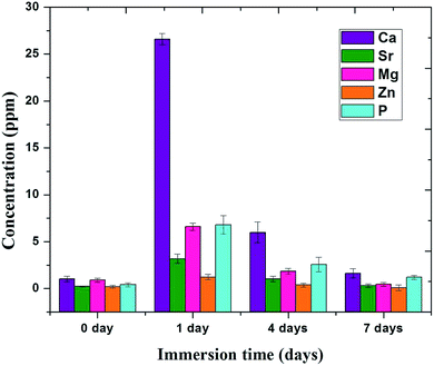 | ||
| Fig. 10 ICP-AES analysis of M-HAP coating on 700 keV HELCDEB-treated Ti at different immersion times. | ||
4. Conclusions
In this study, a Sr, Mg and Zn-substituted HAP coating was obtained on HELCDEB-treated Ti by pulsed electrodeposition. The results are summarized as follows.1. The presence of functional groups in the M-HAP coating was confirmed by the FT-IR and Raman results and the effect of Sr, Mg and Zn substitution on the M-HAP was confirmed by XRD studies.
2. SEM images exhibited typical flower-like morphology with diameters of a few micrometers (∼8 μm) on the HELCDEB-treated Ti samples. The EDAX and XPS studies revealed the presence of mineral ions (Sr, Mg, Zn, Ca, P and O) in the resultant coating.
3. The M-HAP coating on the 700 keV HELCDEB-treated Ti possesses a higher adhesion strength than the M-HAP coating on 500 keV HELECDEB-treated Ti and on untreated Ti.
4. The electrochemical results revealed that the M-HAP coating on 700 keV HELCDEB-treated Ti showed higher corrosion protection compared with the untreated Ti and the other coatings.
5. The ICP-AES results showed that no large-scale dissolution occurred from the M-HAP coating in the SBF environment for 7 days, which proved the stability of the coating.
In summary, the HELCDEB treatment of Ti enhances the corrosion and mechanical properties of the M-HAP coating and it may be suitable for use in orthopedics. The biological studies of the resultant coating will be published later.
Acknowledgements
One of the authors D. Gopi acknowledges the major financial support from the Department of Science and Technology, New Delhi, India (DST) and Council of Scientific and Industrial Research, New Delhi, India (CSIR) in the form of major research projects. D. Gopi and L. Kavitha also acknowledge UGC, New Delhi, India for the Research Award (Ref. no. F. 30-1/2013(SA-II)/RA-2012-14-NEW-SC-TAM-3240 and F. 30-1/2013(SA-II)/RA-2012-14-NEW-GE-TAM-3228) (2012–2014), respectively.References
- J. Cizek, K. A. Khor and Z. Prochazka, Mater. Sci. Eng., C, 2007, 27, 340 CrossRef CAS PubMed.
- A. Letic-Gavrilovic, R. Scandurra and K. Abe, Dent. Mater. J., 2000, 19, 99 CAS.
- C. G. Ambrose and T. O. Clanton, Ann. Biomed. Eng., 2004, 32, 171 CrossRef.
- M. Vallet-Regi and J. M. Gonzalez-Calbet, Prog. Solid State Chem., 2004, 41, 3130 Search PubMed.
- S. V. Dorozhkin and M. Epple, Angew. Chem., Int. Ed., 2002, 41, 1 CrossRef.
- J. Yan, J. Sun, P. K. Chu, Y. Han and Y. Zhang, J. Biomed. Mater. Res., Part A, 2013, 101, 2465 CrossRef PubMed.
- E. Canalis, M. Hott, P. Deloffre, Y. Tsouderos and P. J. Marie, Bone, 1996, 18, 517 CrossRef CAS.
- E. Bonnelye, A. Chabadel, F. Saltel and P. Jurdic, Bone, 2008, 42, 129 CrossRef CAS PubMed.
- K. K. Johal, G. M. Suarez and J. I. E. Garcia, J. Mater. Sci.: Mater. Med., 2002, 13, 375 CrossRef CAS.
- S. Pina, P. M. Torres, F. G. Neunhoeffer, J. Neubauer and J. M. F. Ferreira, Acta Biomater., 2010, 6, 928 CrossRef CAS PubMed.
- E. Buache, F. Velard, E. Bauden, C. Guillaume, E. Jallot, J. M. Nedelec, D. L. Maquin and P. Laquerriere, Acta Biomater., 2012, 8, 3113 CrossRef CAS PubMed.
- N. D. Ravi, R. Balu and T. S. Sampath Kumar, J. Am. Ceram. Soc., 2012, 95, 2700 CrossRef CAS PubMed.
- S. Wallach, Magnesium Trace Elem., 1990, 9, 1 CAS.
- J. E. Sojka and C. M. Weaver, Nutr. Rev., 1995, 53, 71 CrossRef CAS PubMed.
- H. Zreiqat, C. R. Howlett, A. Zannettino, P. Evans, G. S. Tanzil, C. Knabe and M. Shakibaei, J. Biomed. Mater. Res., 2002, 62, 175 CrossRef CAS PubMed.
- M. Okazaki, Y. Yamasaki, Y. Yoshida, A. Shimazu, T. Uchida, T. Kubo, Y. Akagawa, Y. Hamada, J. Takahashi and N. Matsuura, J. Biomed. Mater. Res., 2002, 62, 99 CrossRef PubMed.
- Y. Tang, H. F. Chappell, M. T. Dove, R. J. Reeder and Y. J. Lee, Biomaterials, 2009, 30, 2864 CrossRef CAS PubMed.
- V. Stanic, S. Dimitrijevi, J. A. Stankovic, M. Mitri, B. Joki, I. B. Plecas and S. Raicevi, Appl. Surf. Sci., 2010, 256, 6083 CrossRef CAS PubMed.
- S. Sutha, G. Karunakaran and V. Rajendran, Ceram. Int., 2013, 39, 5205 CrossRef CAS PubMed.
- H. S. Hsieh and J. M. Navia, J. Nutr., 1980, 110, 1581 CAS.
- J. T. Kim, S. H. Baek, S. H. Lee, E. K. Park, E. C. Kim, I. S. Kwun and H. I. Shin, J. Med. Food, 2009, 12, 118 CrossRef CAS PubMed.
- M. Yamaguchi, J. Trace Elem. Exp. Med., 1998, 11, 119 CrossRef CAS.
- D. Gopi, S. Nithiya, E. Shinyjoy and L. Kavitha, Spectrochim. Acta, Part A, 2012, 92, 194 CrossRef CAS PubMed.
- D. Gopi, S. Ramya, D. Rajeswari, M. Surendiran and L. Kavitha, Colloids Surf., B, 2014, 114, 234 CrossRef CAS PubMed.
- D. Gopi, S. Nithiya, E. Shinyjoy, D. Rajeswari and L. Kavitha, Ind. Eng. Chem. Res., 2014, 53, 7660 CrossRef CAS.
- V. Aina, G. Lusvardi, B. Annaz, I. R. Gibson, F. E. Imrie, G. Malavasi, L. Menabue, G. Cerrato and G. Martra, J. Mater. Sci.: Mater. Med., 2012, 23, 2867 CrossRef CAS PubMed.
- S. C. Cox, P. Jamshidi, L. M. Grover and K. K. Mallick, Mater. Sci. Eng., C, 2014, 35, 106 CrossRef CAS PubMed.
- K. Elayaraja, P. Rajesh, M. I. Ahymah Joshy, V. Sarath Chandra, R. V. Suganthi, J. Kennedy, P. K. Kulriya, I. Sulania, K. Asokan, D. Kanjilal, D. K. Avasthi, H. K. Varma and S. N. Kalkura, Mater. Chem. Phys., 2012, 134, 464 CrossRef CAS PubMed.
- C. Dong, A. Wu, S. Hao, J. Zou, Z. Liu, P. Zhong, A. Zhang, T. Xu, J. Chen, J. Xu, Q. Liu and Z. Zhou, Surf. Coat. Technol., 2003, 163–164, 620 CrossRef CAS.
- Q. F. Guan, H. Zou, G. T. Zou, A. M. Wu, S. Z. Hao, J. X. Zou, Y. Qin, C. Dong and Q. Y. Zhang, Surf. Coat. Technol., 2005, 196, 145 CrossRef CAS PubMed.
- D. I. Proskurovsky, V. P. Rotshtein, G. E. Ozur, A. B. Markov, D. S. Nazarov, V. A. Shulov, F. Yu, R. Ivanov and G. Buchheit, J. Vac. Sci. Technol., A, 1998, 16, 2480 CAS.
- D. Gopi, D. Rajeswari, S. Ramya, M. Sekar, R. Pramod, J. Dwivedi, L. Kavitha and R. Ramaseshan, Appl. Surf. Sci., 2013, 286, 83 CrossRef CAS PubMed.
- D. Gopi, A. Karthika, M. Sekar, L. Kavitha, R. Pramod and J. Dwivedi, Mater. Lett., 2013, 105, 216 CrossRef CAS PubMed.
- J. H. Lin, C. H. Chang, Y. S. Chen and G. T. Lin, Surf. Coat. Technol., 2006, 200, 3665 CrossRef CAS PubMed.
- W. Xia, C. Lindahl, J. Lausmaa, P. Borchardt, A. Ballo, P. Thomsen and H. Engqvist, Acta Biomater., 2010, 6, 1591 CrossRef CAS PubMed.
- D. Gopi, S. Ramya, D. Rajeswari and L. Kavitha, Colloids Surf., B, 2013, 107, 130 CrossRef CAS PubMed.
- A. Kar, K. S. Raja and M. Misra, Surf. Coat. Technol., 2006, 201, 3723 CrossRef CAS PubMed.
- D. Gopi, V. C. A. Prakash and L. Kavitha, Mater. Sci. Eng., C, 2009, 29, 955 CrossRef CAS PubMed.
- Y. Han, T. Fu, J. Lu and K. Xu, J. Biomed. Mater. Res., 2001, 54, 96 CrossRef CAS.
- D. Gopi, V. C. A. Prakash, L. Kavitha, S. Kannan, P. R. Bhalaji, E. Shinyjoy and J. M. F. Ferreira, Corros. Sci., 2011, 53, 2328 CrossRef CAS PubMed.
- M. Popa, E. Vasilescu, P. Drob, M. V. Popa, J. M. C. Moreno, C. Vasilescu and S. I. Drob, J. Am. Ceram. Soc., 2012, 95, 3807 CrossRef CAS PubMed.
- D. Gopi, J. Indira and L. Kavitha, J. Appl. Electrochem., 2013, 43, 331 CrossRef CAS.
- Y. Y. Zhang, J. Tao, Y.-C. Pang, W. Wang and T. Wang, Trans. Nonferrous Met. Soc. China, 2006, 16, 633 CAS.
- Y. W. Gu, K. A. Khor, D. Pan and P. Cheang, Biomaterials, 2004, 25, 3177 CrossRef CAS PubMed.
- R. Drevet, H. Benhayounea, L. Worthama, S. Potirona, J. Dougladeb and D. L. Maquina, Mater. Charact., 2010, 61, 786 CrossRef CAS PubMed.
- ASTM standard F 1044-05, ASTM International, West Conshohocken, PA.
- T. Kokubo and H. Takafama, Biomaterials, 2006, 27, 2907 CrossRef CAS PubMed.
- D. Gopi, A. Karthika, S. Nithiya and L. Kavitha, Mater. Chem. Phys., 2014, 144, 75 CrossRef CAS PubMed.
- J. Guerra-Lopez, R. Pomes, C. O. D. Vedova, R. Vina and G. Punte, J. Raman Spectrosc., 2001, 32, 255 CrossRef CAS PubMed.
- L. Oliveira, R. L. Reis and P. Li, J. Biomed. Mater. Res., Part B, 2007, 83, 258 CrossRef PubMed.
- D. Guo, K. Xu, X. Zhao and Y. Han, Biomaterials, 2005, 26, 4073 CrossRef CAS PubMed.
- R. N. Panda, H. Ming-Fa, R. J. Chung and T. S. Chin, J. Appl. Phys., 2001, 40, 5030 CrossRef CAS.
- W. Xia, C. Lindahl, J. Lausma, P. Borchardt, A. Ballo, P. Thomsen and H. Engqvist, Acta Biomater., 2010, 6, 1591 CrossRef CAS PubMed.
- J. Chen, Y. Song, D. Shan and E. H. Han, Corros. Sci., 2011, 53, 3281 CrossRef CAS PubMed.
- J. Li, L. Zhang and Y. Zuo, Appl. Surf. Sci., 2008, 254, 2844 CrossRef CAS PubMed.
- A. Dey and A. K. Mukhopadhyay, Int. J. Appl. Ceram. Technol., 2014, 11, 65 CrossRef CAS PubMed.
| This journal is © The Royal Society of Chemistry 2014 |

