Zailei Zhang*a,
Guangwei Kana,
Wenfeng Rena,
Qiangqiang Tan*a,
Ziyi Zhongb and
Fabing Su*a
aState Key Laboratory of Multiphase Complex Systems, Institute of Process Engineering, Chinese Academy of Sciences, Beijing, China 100190. E-mail: zhangzl@ipe.ac.cn; qtan@ipe.ac.cn; fbsu@ipe.ac.cn; Fax: +86-10-82544851; Tel: +86-10-82544850
bInstitute of Chemical Engineering and Sciences, A*star, 1 Pesek Road, Jurong Island, Singapore 627833
First published on 23rd July 2014
We report a solvothermal synthesis of Ni0.33Mn0.33Co0.33Fe2O4 (NMCFO) nanoparticles anchored on the surface of oxidized carbon nanotubes (OCNT) to form NMCFO/OCNT nanocomposites as advanced anode materials in Li-ion batteries. Ni(CH3COO)2, Mn(CH3COO)2, Co(CH3COO)2, and FeCl3 were employed as the metal precursors and CH3COONa, HOCH2CH2OH and H2O as the mixed solvent in the synthesis. The obtained samples were characterized by X-ray diffraction, thermogravimetric analysis, inductively coupled plasma optical emission spectrometry, X-ray photoelectron spectroscopy, transmission electron microscopy, and scanning electron microscopy. It is found that the OCNT provided functional groups on the outer walls to nucleate and anchor NMCFO nanoparticles (5–20 nm), while retaining the inner walls intact with high conductivity. Compared with the bare NMCFO nanoparticles, NMCFO/OCNT composites showed a significantly improved electrochemical performance because OCNT can substantially inhibit the aggregation of NMCFO nanoparticles and buffer the volume change, and moreover, the inner walls of OCNT provide excellent electronic conduction pathways. This work opens an effective way for the fabrication of ferrite-based metal oxide/OCNT hybrids as promising anode materials for Li-ion batteries.
Iron-based oxides have recently received increased attention as very promising anode materials for rechargeable LIBs because of their high theoretical capacity, non-toxicity, low cost, and improved safety.24 Meanwhile, nanostructured carbon nanotubes (CNT) are also promising anode materials for LIBs due to their large electrode/electrolyte contact area and active surface, high chemical stability and conductivity, and good mechanical strength.25–31 Therefore, in the past decade efforts were made to synthesize CNT–metal oxides nanoparticle hybrids or composites.32,33 The binding between CNT and metal oxides nanoparticles are quite diverse, e.g., by noncovalent interactions (such as π–π stacking and hydrophobic wrapping), electrostatic interactions, or by covalent bonding through functionalization of outer wall by oxidation.34–36 Xu et al. prepared NiO/CNT composites as anode material using nitric acid treated CNT, which maintained the capacity at ∼800 mA h g−1 after 50 discharge–charge cycles at a current density of 50 mA g−1.37 Zhuo et al. prepared Co3O4/CNT composites using oxidative treatment on CNT, which left a large number of acidic groups on the surface, showing 776 mA h g−1 at the 100th cycle at a current density of 200 mA g−1.15 In addition, Wang et al. found that the carbon coated α-Fe2O3 hollow nanohorns supported on nitric acid treated CNT backbones exhibited a very stable capacity retention of 800 mA h g−1 over 100 cycles at a current density of 500 mA g−1.12 From these literature results, it is found that metal oxides/CNT hybrids, in which the CNT are pre-oxidized partially, exhibit good electrochemical performance by virtue of their advantageous structural features. However, so far there has no report showing attractive hybrid containing multicomponent ferrite-based metal oxides nanoparticles and CNT for lithium storage.
Herein, we report a novel synthesis of Ni0.33Mn0.33Co0.33Fe2O4 (NMCFO)/oxidized carbon nanotubes (OCNT) composites by directly growing NMCFO nanoparticles on OCNT. In this strategy, NMCFO nanoparticles are uniformly dispersed on the surface of OCNT to form NMCFO/OCNT network nanocomposites. Compared with the bare NMCFO nanoparticles, NMCFO/OCNT exhibits significantly improved electrochemical performance with excellent cycling stability and high rate performance, suggesting a potential application as anodes in future LIBs with a high energy density.
Fig. 1b shows the TG curves of all the samples. The impurity of CNT is around 4.2 wt%, probably due to the presence of metal catalyst (Fe/Co/Ni) residue after the synthesis of CNT. However, these metal nanoparticles have been removed by calcination followed with washing by dilute hydrochloric acid for OCNT. It can be seen that the weight loss derived from carbon combustion is located between 360 and 600 °C for OCNT, lower than that for CNT (400–650 °C), indicating the lowered combustion temperature of OCNT after the oxidation treatment. For the bare NMCFO nanoparticles, the weight loss of about 1.2 wt% may be derived from the trace amount of organic residue on their surface. For NMCFO/OCNT composites, the weight loss starts at about 230 °C, lowering than that of OCNT (360 °C). This is because the presence of metal oxides (NMCFO) can catalytically promote the carbon combustion process at a lower temperature.41 The measured weight loss of NMCFO/OCNT-1, NMCFO/OCNT-2, NMCFO/OCNT-3, and NMCFO/OCNT-4 is about 41.7, 36.2, 28.9, and 16.7 wt% respectively in the temperature range from 100 to 1000 °C, which can be ascribed to the decomposition of organic species and the combustion of OCNT, suggesting that the weight percentage of OCNT is approximately at 40.5, 35.0, 27.7, and 15.5 wt% in the samples of NMCFO/OCNT-1, NMCFO/OCNT-2, NMCFO/OCNT-3, and NMCFO/OCNT-4, respectively.
Fig. 2a shows the TEM image of NMCFO nanoparticles with a size range of 5–20 nm. Most of the NMCFO nanoparticles are agglomerated together due to the surface effect of nanoparticles.42 Meanwhile, the HRTEM image of these nanoparticles (Fig. 2b) reveals that the lattice fringe spacing is about 0.293 nm, corresponding to the interplanar distance of (220) planes in NMCFO,40 and each nanoparticle is actually a single crystal. The EDX spectrum of NMCFO nanoparticles in Fig. 2c demonstrates the presence of Ni, Mn, Co, Fe, and O elements. The elemental mapping images based on the NMCFO nanoparticles show the homogeneous distribution of all the five elements (Ni, Mn, Co, Fe, and O) (Fig. S2†). The atomic ratio of Ni, Mn, Co, and Fe elements is approximate 1:
1
:
1
:
6 from ICP-OES analysis. In fact, it is possible to tune the atomic ratio of NixMnyCozFe2O4 (x + y + z = 1, 0 < x, y, z < 1) by controlling the ratio of raw materials (Ni(CH3COO)2, Mn(CH3COO)2, and Co(CH3COO)2). For example, for Ni0.2Mn0.4Co0.4Fe2O4, the used raw materials amount is 0.2 mmol Ni(CH3COO)2, 0.4 mmol Mn(CH3COO)2, and 0.4 mmol Co(CH3COO)2 (Fig. S3a†); while for Ni0.4Mn0.4Co0.2Fe2O4, the corresponding amount is 0.4 mmol Ni(CH3COO)2, 0.4 mmol Mn(CH3COO)2, and 0.2 mmol Co(CH3COO)2 (Fig. S3b†). The SEM image in Fig. 2d shows that the formed NMCFO/OCNT precursors have network structure. NMCFO and OCNT in NMCFO/OCNT precursors can be easily differentiated by the brightness contrast in the TEM images (Fig. S4b and c†), which shows that the NMCFO are amorphous and coated on the surface of OCNT, well agreement with the XRD result (Fig. S4a†). Also, it is very important to identify the amorphous nature of NMCFO precursors, as it helps to understand the formation process of the crystallized NMCFO.
![]() | ||
Fig. 2 TEM images (a and b), and EDX spectrum of NMCFO nanoparticles (c), and SEM of amorphous NMCFO/OCNT precursors (d). |
The SEM image of Fig. 3a shows that the OCNT are coated with NMCFO nanoparticles forming the network structure after adding 0.20 g OCNT in NMCFO/OCNT-1. The surface of the OCNT becomes coarser after coating with the smaller NMCFO nanoparticles. When the OCNT amount is decreased to 0.15 (Fig. 3b) and 0.10 g (Fig. 3c and d), most of NMCFO nanoparticles are coated on the surface of OCNT forming the NMCFO/OCNT-2 and NMCFO/OCNT-3 network composites. With further decrease of the OCNT amount to 0.05 g (Fig. S5a†), larger portion of NMCFO nanoparticles is aggregated together but still coated on the surface of OCNT. Therefore, it is possible to tune the nanocomposites network structure and composition by varying the synthesis conditions such as the amount of OCNT and raw chemicals, as well as the reaction time and temperature.
![]() | ||
Fig. 3 SEM images of NMCFO/OCNT-1 (a), NMCFO/OCNT-2 (b), NMCFO/OCNT-3 (c), and the high-magnification of NMCFO/OCNT-3 (d). |
More detailed structural information can be obtained from the TEM results. The TEM images of NMCFO/OCNT-1 in Fig. 4a and b show that smaller NMCFO nanoparticles are highly dispersed on the surface of OCNT after adding 0.20 g OCNT. Fig. 4c shows the high resolution TEM image of NMCFO/OCNT-1, in which, the NMCFO nanoparticles with a size of around 15 nm are attached to the surface of OCNT and the lattice with an interplanar spacing of about 0.293 nm corresponds to the (220) plane of NMCFO, consistent with the observation in Fig. 2b. The HRTEM image also reveals that the inner walls of graphitic carbon nanotubes in the hybrid are still well maintained or not broken (Fig. 4c), suggesting that the inner walls of OCNT were not destroyed by the oxidation treatment and the subsequent reactions during the hybrid synthesis. After addition of 0.15 g and 0.10 g OCNT, the samples of NMCFO/OCNT-2 (Fig. 4d and e) and NMCFO/OCNT-3 (Fig. 4f and g) with uniformly coated NMCFO nanoparticles on the surface of OCNT composites are obtained. However, with further decrease of the OCNT amount to 0.05 g, most of NMCFO nanoparticles and OCNT are aggregated together (Fig. S5b and c†). The crystal NMCFO and OCNT in NMCFO/OCNT composites also could be easily differentiated by the brightness contrast in the TEM images (Fig. 4, S5b and c†). These crystal NMCFO nanoparticles are attached to the surface of OCNT to form network composites, consistent with the above SEM observation.
The formation process of NMCFO/OCNT composites is illustrated in Fig. 5. Firstly, Ni2+, Mn2+, Co2+, and Fe3+ dissolved in the solvent are adsorbed on the external surface of the OCNT, because OCNT with functional groups on the outer walls is a good metal ion adsorbent (Fig. 5a).15,38 With the increase of the temperature to 110 °C, these metal ions are accumulated specifically on the outer wall by the oxidative functional groups on OCNT.35 These oxidative functional groups can act as heterogeneous nucleation sites in the early reaction stage to facilitate the formation of small amorphous nanoparticles during the precipitation.43 Thereafter, the small amorphous NMCFO nanoparticles are generated and aggregated on the surface of OCNT via the reaction (0.33Ni2+ + 0.33Mn2+ + 0.33Co2+ + 2Fe3+ + 4H2O → Ni0.33Mn0.33Co0.33Fe2O4 + 8H+) with the water generated from the metal precursors (Fig. 5b). With the further increase of the temperature to 200 °C, the amorphous NMCFO nanoparticles are crystallized to form crystal NMCFO nanoparticles (Fig. 5c), which are also coated on the surface of the OCNT. And in the last stage, the crystal NMCFO/OCNT network composites are developed and formed (Fig. 5d). In case with addition of more OCNT, it will have more oxidative functional groups acting as the adsorption sites for the given amounts of Ni2+, Mn2+, Co2+, and Fe3+. As a result, the formed NMCFO will become smaller in size and be dispersed more uniformly on the OCNT surface as shown in Fig. 3, 4, and S5.† This is because of the dispersing effect of OCNT. In a control experiment, it was failed to get the uniform distribution of NMCFO nanoparticles and CNT network composites by using 0.10 g CNT without oxidization. Therefore, it is clear that the oxidative functional groups on the external surface of OCNT are the nucleation centers and play the key role in the growth of NMCFO nanoparticles.
Fig. 6a presents the CV curves of NMCFO/OCNT-1 in the first two cycles, and in the 51st cycle after 50 rate discharge–charge cycles at a scan rate of 0.1 mV s−1. In the first scan, two cathodic peaks are observed at about 0.57 and 0.78 V, which correspond to the conversion reactions of Fe3+, Co2+, Ni2+, and Mn2+ to their metallic states and the formation of Li2O, respectively. The broad anodic peak from 1.0 V to 2.0 V can be ascribed to the oxidation reactions of metallic Fe, Co, Ni, and Mn. The quaternary metal oxide NMCFO stores Li through reversible formation and decomposition of Li2O. In the second scan, the reduction peaks are shifted to 0.73 and 1.51 V respectively. The peak intensity and integral areas of the 51st cycle after 50 rate discharge–charge cycles measurement are almost the same as those of the second cycle for NMCFO/OCNT-1, which demonstrates the good reversible oxidation–reduction reaction, and reversible formation and decomposition of Li2O.44 The discharge and charge capacities in the first run, and their initial coulombic efficiencies are shown in Fig. S6† and Table 1. The discharge–charge capacity for NMCFO component may be based on the oxidation–reduction of metallic Fe, Co, Ni, and Mn nanoparticles to Ni0.33Mn0.33Co0.33Fe2O4 respectively via the reaction: 4Li2O + 0.33Ni + 0.33Mn + 0.33Co + 2Fe ↔ Ni0.33Mn0.33Co0.33Fe2O4 + 8Li+ + 8e−. A distinct voltage plateau can be clearly identified at ca. 0.8–0.9 V, which is corresponding to the reduction of Fe3+ to Fe, Co2+ to Co, Ni2+ to Ni, and Mn2+ to Mn during the initial discharge process (Fig. S6†). Meanwhile, a clear plateau is observed in the charge process at ca. 1.5–2.5 V, which is corresponding to the oxidation of Fe to Fe3+, Co to Co2+, Ni to Ni2+, and Mn to Mn2+ during the initial charge process (Fig. S6†). The carbon lithiation and delithiation voltage plateau are not observed, because of the small contribution of carbon to the overall anode capacity in term of the previous reports (Fig. S6†).39
Samples | C1st-dia (mA h g−1) | C1st-chb (mA h g−1) | CEinc (%) | ACE2ndd (%) | ACF100the (% per cycle) | C100thf (mA h g−1) |
---|---|---|---|---|---|---|
a C1st-di, the first discharge capacity.b C1st-ch, the first charge capacity.c CEin, the initial coulombic efficiency.d ACE2nd, the average coulombic efficiency after second cycles.e ACF100th, average capacity fading rate during 100 cycles.f C100th, the discharge capacity after 100 cycles. | ||||||
NMCFO | 1541.3 | 723.2 | 46.9 | 94.5 | 0.804 | 141.8 |
NMCFO/OCNT-1 | 1092.1 | 692.2 | 63.4 | 97.4 | 0.028 | 673.7 |
NMCFO/OCNT-2 | 1252.2 | 771.5 | 61.6 | 97.2 | 0.050 | 733.1 |
NMCFO/OCNT-3 | 1452.2 | 909.1 | 62.7 | 97.0 | 0.219 | 710.3 |
NMCFO/OCNT-4 | 1495.1 | 928.5 | 62.1 | 96.8 | 0.455 | 506.3 |
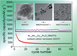
The cycling performance in Fig. 6b and Table 1 shows that the discharge capacity of NMCFO/OCNT-1, NMCFO/OCNT-2, NMCFO/OCNT-3, NMCFO/OCNT-4 after 100 cycles is around 673.7, 733.1, 710.3, and 506.3 mA h g−1, respectively, which is higher than that of NMCFO (141.8 mA h g−1) and OCNT (296.4 mA h g−1) (Fig. S7†). It should be mentioned that the capacity of NMCFO/OCNT composites after 100 cycles is lower than that of the CoNiO nanowire arrays loaded on TiO2 nanotubes (1097 mA h g−1 after 40 cycles at a current density of about 606 mA g−1),45 and carbon-coated graphene/Fe3O4 nanosheets (920 mA h g−1 after 100 cycles at a current density of 200 mA g−1).46 As reported in ref. 40, the discharge capacity after 60 cycles was about 487.2 mA h g−1 for NMCFO mesoporous nanospheres, which is higher than that of the NMCFO nanoparticles (141.8 mA h g−1 after 100 cycles). Probably the porosity structure of NMCFO nanospheres could buffer the large volume change of anodes caused by the conversion reaction during the repeated Li+ insertion/extraction,47 and be an advantage for lithium-storage applications that require rapid ion transport and large contact area between the electrode and the electrolyte. In addition, the more added acetylene black in ref. 40 could inhibit the aggregation of NMCFO nanospheres, and provide effective electronic conduction pathways. After 200 cycles, the discharge capacity of NMCFO/OCNT-1 at the current densities of 50 and 500 mA g−1 still maintains at about 624.8, and 421.0 mA h g−1, as shown in Fig. S8,† indicating the good cycling performance of the composite anode. The average coulombic efficiency after the second cycle and average capacity fading rate during the 100 cycles of all above NMCFO/OCNT samples is shown in Table 1. Clearly, in a certain range, the more the OCNT added, the better the electrochemical performances will be for the formed network structure composites.
Fig. 6c showed the charge–discharge profiles of NMCFO/OCNT-1 of the first cycles at different current densities. NMCFO/OCNT-1 has a better rate performance than NMCFO/OCNT-1 as shown in Fig. 6d and S9.† In favor of the presence of conductive OCNT, these network composite materials exhibit much lower resistance than the NMCFO nanoparticles, as evidenced by the drastically reduced diameter of these semicircle at high-frequency region in the electrochemical impedance spectroscopy (EIS) patterns (Fig. S10†). As a result of lower contact and charge-transfer impedances, lithium ion diffusion and electron transfer are facilitated to give the greatly enhanced electrochemical performance of the NMCFO/OCNT composites. These results indicate that NMCFO/OCNT exhibits high electrochemical reversibility. The introduced OCNT can highly disperse NMCFO nanoparticles, prevent their aggregation, buffer the volume change, and promote efficient Li+ diffusion and electronic conduction, leading to better cycling stability and high rate performances.48,49 It should be pointed out that this preparation method is extendable to the preparation of other ferrite-based metal oxide (such as ZnaNibMncCodFe2O4, 0 ≤ a, b, c, d ≤ 1, a + b + c + d = 1 (ref. 40))/OCNT hybrid, and these materials can also be used as catalysis50,51 and supercapacitor, etc.52
Footnote |
† Electronic supplementary information (ESI) available. See DOI: 10.1039/c4ra04483e |
This journal is © The Royal Society of Chemistry 2014 |