Power-law rheology characterization of biological cell properties under AFM indentation measurement

Tianxiao Niu and Guoxin Cao*
HEDPS, Center for Applied Physics and Technology, Department of Mechanics and Engineering Science, College of Engineering, Peking University, Beijing, 100871, China. E-mail: caogx@pku.edu.cn; Tel: +86 010 62756284

Received 7th April 2014 , Accepted 11th June 2014

First published on 12th June 2014


Abstract

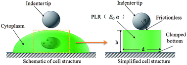
Using finite element modeling, the mechanical properties of biological cells are investigated based on the power-law rheology (PLR) model under atomic force microscopy (AFM) indentation testing. Three different loading modes, including relaxation tests, quasi-static indentation and dynamic indentation are considered. After correcting the effects of the Hertz contact radius and substrate stiffening, the parameters of E0 and α in the PLR model can be accurately determined from all three loading modes under AFM indentation. In addition, for all the three indentation loading modes, the aforementioned two effects are not sensitive to the material model used for the cell (e.g., the values of α and E0) but only depend upon the ratio of the indentation depth to the cell thickness. Because the parameters determined from various loading modes can be validated among each other, the AFM indentation will be a very effective route to accurately determine the cell mechanical properties based on the PLR model.


1. Introduction

There is a close relationship between the mechanical properties of a cell and their normal physiological activities. For example, cancer cells change their mechanical properties1–3 and red blood cells transport oxygen through narrow blood capillaries by changing their shape.4–7 Accurate determination of cell mechanical properties may shed light on the state of health as well as the disease mechanism.8 The mechanical behavior of biological cells is typically described using continuum mechanics models, and the parameters associated with those models are the effective mechanical properties of the cells, which can be measured by experimentation.

In experiments, the cell properties are typically measured using magnetic twisting cytometry (MTC),9–12 micropipette aspiration (MPA),13 uniaxial stretching,14 compression15 and scanning probe indentation.16 Among these methods, the indentation using atomic force microscopy (AFM) has been one of the most popular methods for measuring the mechanical behavior of living cells because it is fast, inexpensive and convenient (commercialized and easily accessible).16–22 In addition, the experimental setups used in other methods are highly customized, and the loading conditions of cells vary because of the selection of different system parameters, which affect the measured cell properties. For example, the degree of bead embedding is unknown in MTC measurements, which causes an ill-defined contact between the probe and the cell surface. The contact geometry is also poorly defined in other techniques used in cell compression or tension tests;16 in MPA measurements, the cell shape should be assumed to be spherical, and the cell properties not only depend on cell radius, but also relate to the pipette radius and the fillet radius of the pipette.23

In earlier studies, cells were typically modeled as linear elastic or linear viscoelastic materials.4,15,20,21,24–26 However, the experimental results suggested that those continuum models cannot accurately capture the rheological behavior of biological cells, whereas this behavior can be properly described using the power-law rheology (PLR) model.9,10 Recently, an increasing number of studies have shown that the mechanical behavior of biological cells follows the PLR model.11–14,16,23,27–29 However, only a few studies have examined the use of the AFM indentation technique based on the PLR model for analyzing the mechanical behavior of cells.16

In AFM indentation tests, a cell is typically mounted on a substrate that is orders of magnitude stiffer than the cell. Because of low-cell thickness, the indentation force–displacement curve will be influenced, which has been widely reported.20,21,30 Although the substrate effect will be minimized in shallow indentation, it is highly difficult to accurately determine the contact area in shallow indentation due to the surface roughness, low-cell stiffness and adhesive force between the indenter tip and cell.31,32 In the present work, using finite element modeling (FEM), a comprehensive indentation analysis on the basis of the PLR model is developed to investigate the mechanical behavior of cells, and substrate-stiffening effect, as well as the correction for the Hertz contact area, is also considered. This study can help us to effectively understand the mechanical properties of the cell on the basis of the PLR model using the commercial AFM set-up.

2. Computational methods

2.1 PLR model

The dynamic modulus of the cell in the frequency domain can be fitted as the PLR model:9
 
image file: c4ra03111c-t1.tif(1)
where ω is the radian frequency of harmonic load; the damping parameter η = tan(απ/2); E0 and ω0 are scale factors for stiffness and frequency (i.e., ω0 = 1 rad s−1), respectively; α is the power-law parameter; and iμω is a Newtonian viscous term, which can be neglected at low frequencies. In the frequency domain, the storage modulus E′ (the real part of E*) and the loss modulus E′′ (the imaginary part of E*) can be expressed as16
 
image file: c4ra03111c-t20.tif(2)
where E0 is the storage modulus with α = 0.

The PLR model can be transferred from the frequency domain to the time domain, according to the following formula:

 
image file: c4ra03111c-t2.tif(3)

Ee represents long-term modules, which is set to zero in the PLR model. In the time domain, the relaxation modulus in the PLR model can be obtained as13,23

 
image file: c4ra03111c-t3.tif(4)
where Γ( ) is the gamma function and t is the relaxation time.

2.2 Simulation method

Because of heterogeneity, active internal force, irregular geometry and complex viscoelasticity, it is highly difficult to find a proper continuum model to perfectly describe the experimental results. In addition, there should be a compromise between the accuracy of the selected model and its complexity, i.e., a more complex model (including more parameters) can provide a more accurate description of the mechanical behavior of the cell but the accuracy or reliability of determining these parameters from the experiments will be certainly decreased. In the present work, the PLR is used to simulate cell indentation behaviour, which is studied using FEM. All the FEM simulations were carried out using ABAQUS v6.10.

Although biological cells are irregularly shaped (as shown in Fig. 1(a)), cells will expand themselves after being mounted on a substrate, and the curvature of cell surface as well as the cell lateral size are significantly larger than the AFM tip radius. Thus, the effect of the real shape of a biological cell on its indentation response is small (can be neglected), and the cell indentation behavior is similar to the cell in a regular shape (such as an axisymmetric disk as shown in Fig. 1(b)), which has been widely used in studying the mechanical behavior of cells.4,20,21,30,33,34 The simplified geometry will be described by two parameters, average diameter d and thickness h, and can be modeled by the 2D axisymmetric element in FEM. To obtain an accurate contact radius, the size of the cell surface elements is set to be less than 0.5% of the indenter tip radius. The standard AFM tip is sharp and is likely to cause a very high stress concentration, leading to highly nonlinear behavior; moreover, it may even damage the cell membrane. Typically, a spherical tip is used instead of a conventional tip in cell AFM indentation, and the radius of the tip is about several microns.20,21,30 In the present work, the geometric sizes of the cell are selected as: h = 10 μm, d = 20 μm and the indenter tip radius R = 4 μm, which are close to the values reported in previous experiments.30,34,35


image file: c4ra03111c-f1.tif
Fig. 1 (a) Schematic of a cell in spherical indentation; and (b) simplified cell structure used in modeling.

In the present work, the cell is simulated by the PLR model (eqn (4)). In the model, the parameter E0 = 2.9 kPa, Poisson's ratio ν = 0.49 and power-law parameter α = 0–0.4 cover the reported PLR model parameter range.13,14,16,23,28 Both the spherical tip and the substrate are modeled as rigid bodies because they are usually several orders stiffer than the cells. The contact between indenter tip and cell top face is considered to be frictionless, and the adhesion force between them will be studied in future. The bottom of the cells is fully constrained to simulate the cells perfectly bonded with substrate. To reduce the nonlinear behavior as well as the substrate stiffening effect, the indentation depth cannot be very large, δ = 0.5–1 μm, which corresponds to the lowest value used in the experiments.30,36

2.3 Loading profile

To fully understand the mechanical response of cells based on the PLR model in AFM indentation, three different loading modes are used in the present work:

(1) Relaxation analysis: relaxation behavior can be obtained by maintaining the indentation displacement (e.g., δ/h = 0.1) for a certain period of time to measure the variation of indentation force with time t (Fig. 2(a)). Indentation force under a spherical tip can be determined by the Hertz contact theory:37

 
image file: c4ra03111c-t4.tif(5)
where E is the elastic modulus of cell and ν is the Poisson's ratio. By plugging the PLR model (eqn (4)) into eqn (5), the cell indentation force will be relaxed with time t as follows:
 
image file: c4ra03111c-t5.tif(6)


image file: c4ra03111c-f2.tif
Fig. 2 Loading profiles in AFM indentation: (a) relaxation test; (b) quasi-static indentation; and (c) dynamic indentation.

(2) Quasi-static indentation analysis: the indentation load is applied by displacement control at a constant loading rate (v = δ/t), and the maximum indentation displacement is set to δ/h = 0.1 (Fig. 2(b)). The indentation force can be expressed as:

 
image file: c4ra03111c-t6.tif(7)

After formally solving the integration, P will be derived as the equation in the form analogous to eqn (6):

 
image file: c4ra03111c-t7.tif(8)
where
 
image file: c4ra03111c-t8.tif(9)

Therefore, the loading history of the quasi-static indentation will increase the indentation force with respect to the same displacement as compared with the relaxation behavior caused by α < 1.

(3) Dynamic indentation analysis: dynamic testing has distinct advantages over quasi-static loading, including higher accuracy in obtaining the initial contact point and lower sensitivity to thermal drift.38,39 A direct indentation displacement (δ0 = 0.02h) is first applied on cells, and a small sinusoidal oscillatory displacement (Δδ = 0.05δ0) is then superimposed on the direct load (Fig. 2(c)), which is expressed as

 
δ = δ0 + Δδ[thin space (1/6-em)]sin(ωt), (10)
where the harmonic oscillatory frequency ω = 2πf. In the present work, the loading frequency range f = 0.01–100 Hz is selected. The resultant indentation force also includes direct and oscillatory parts, which can be expressed as
 
P = ΔP[thin space (1/6-em)]sin(ωt + ϕ) + P0(t), (11)
where ΔP is the amplitude of oscillation,ϕ is the phase lag between the force and displacement and P0(t) is the response of the direct displacement δ0.

3. Result and discussion

3.1 Simulating the PLR model based on the Prony series expansion

In the time domain, the PLR model is employed in FEM simulations by fitting as the Prony series expansion, which has been used to study the mechanical behaviour of cells under MPA [22]. However, the effect of the discrepancy between the original PLR model and the fitted Prony series expansion on determining the mechanical properties of cell (e.g., E0 and α) has not been analyzed. In the present work, the effectiveness of this fitting procedure is examined on the basis of the uniaxial tensile behavior of a cylindrical sample with the PLR material model.

The relaxation modulus is typically fitted as the Prony series expansion, which can be easily implemented in FEM:23,28

 
image file: c4ra03111c-t9.tif(12)

Eins is the instantaneous modulus, gi and τi (i = 1, 2, 3,…, N) are the Prony coefficients, and N is the number of Prony terms. The PLR model (eqn (4)) is typically fitted as the Prony series expansion (eqn (12)) with 5–7 terms, which has shown very good fitting results.23,28 In the present work, least-squares regression is used to fit eqn (4) (the time scale t = 10−3 to 103 s and α = 0–0.4) as a six-term Prony series expansion. With different PLR parameters, the corresponding fitted Prony coefficients (eqn (12)) are used in FEM modeling. The effectiveness of the fitting procedure can be shown by comparing the fitted parameters E*0 and α* from the simulated indentation behaviour, including relaxation behavior, quasi-static tensile and dynamic tensile behaviour, by FEM with the original PLR model (E0 and α), from which the Prony coefficients are fitted. The fitted values E*0 and α* from these three different loading modes are displayed in Fig. 4, 6 and 8, respectively. They match very well with their true values (E0 and α), except some very small fluctuations. Therefore, the PLR model in the present study range can be effectively represented by the fitted Prony series expansion in FEM simulations.


image file: c4ra03111c-f3.tif
Fig. 3 Calculated correction factors fa, fs based on the different material models, including the linear elastic, SLS and PLR models.

image file: c4ra03111c-f4.tif
Fig. 4 Relaxation curve of a cell in AFM indentation, expressed by the normalized indentation force, P/(E0δ3/2R1/2).

image file: c4ra03111c-f5.tif
Fig. 5 Fitted power-law parameters from the AFM indentation relaxation test: (a) α; and (b) E*0/E0, where E*0 is the fitted value of the true value E0.

image file: c4ra03111c-f6.tif
Fig. 6 Variation of the correcting factors for the effects of Hertz contact area and substrate stiffening in quasi-static indentation with the indentation depth, expressed by the relationship between λ0fqafqs/fafs and δ/h.

image file: c4ra03111c-f7.tif
Fig. 7 Fitted power-law parameters from the quasi-static AFM indentation test: (a) α; and (b) E*0/E0, where E*0 is the fitted value of the true value E0.

image file: c4ra03111c-f8.tif
Fig. 8 Relationship between Δδ, magnitude of the applied fluctuating displacement, and ΔP, magnitude of the resulting fluctuating indentation force under various loading frequencies. Value of ΔP is normalized by E0R2 and the value of Δδ is normalized by h.

3.2 The finite size effect on the Hertz contact solution

It has been shown that the Hertz contact solution is not very accurate for describing cell indentation response because of the small size of a cell (including both lateral size and thickness), small indenter tip size and large indentation displacement.20,21,35 The discrepancy between the Hertz contact solution and the true solution of cell indentation can be considered to be caused by: the inaccurate contact radius and substrate stiffening. Based on the Hertz solution, the contact radius of the spherical indenter tip image file: c4ra03111c-t10.tif.37 From the FEM simulation results, it is found that the Hertz solution will underestimate the contact radius (referred as to the contact radius effect). In addition, the finite cell thickness not only affects the contact radius but also interferes with the indentation stress/strain field due to substrate stiffening effect (i.e., the cell becomes stiffer), particularly in the thin region of the cell (referred as to the substrate effect).21,30 In the present work, two factors fa and fs are used to represent the above mentioned two effects, respectively.

For quasi-static indentation behavior based on the elastic model or the relaxation behavior based on the viscous model (e.g., the SLS and PLR models), the values of fa and fs are only dependent upon the current indentation depth, and thus the true indentation force of the cell (calculated from FEM simulations) can be expressed as

 
image file: c4ra03111c-t11.tif(13)

The product of fafs is estimated by the ratio of P/PH and is fitted as the following function

 
image file: c4ra03111c-t12.tif(14)
where A, B and C are fitting parameters. With a decrease in δ/h, the values of fafs converge to 1. The factor fa can be estimated directly by comparing the Hertz contact radius and the true contact radius (e.g., obtained from FEM simulations). Plugging the value of fa into eqn (14), the factor fs is obtained. The calculated values of fa and fs based on the quasi-static indentation behavior of the linear elastic model, and the relaxation responses of the standard linear solid (SLS) model (e.g., the Prony parameters are g1 = 0.5 and τ1 = 10 s) and the PLR model (e.g., α = 0.1–0.4) are shown in Fig. 3. The results show that eqn (13) is valid for describing the quasi-static indentation behavior of the linear elastic model and relaxation responses on the SLS and PLR models. For the PLR model, the values of fs vary slightly with the values of α (as shown by the error bar that covers the results from the different values of α), which is caused by the discrepancy between the original PLR model and the fitted Prony series expansion.

3.3 Relaxation analysis

After plugging the PLR model (eqn (4)), the indentation relaxation behavior of a cell based on the PLR model (eqn (4)) is well described by eqn (13) (displayed as the solid lines in the figure), as shown in Fig. 4. By fitting the FEM relaxation results as eqn (13), the mechanical properties of the cell (E0 and α) can be obtained. Fig. 5(a) and (b) show the fitted results (α* and E*0, expressed by the ratio of E*0/E0) with δ/h = 0.05, 0.1, respectively. In the present study range (α ≤ 0.4, δ/h < 0.1), the fitted value of α is not sensitive to the loading range (δ/h) as well as the accompanying effects, such as the Hertz contact radius and the substrate stiffening, and is very close to its true value. After correcting the effects of inaccurate contact radius and substrate stiffening (by introducing fa and fs), the value of E0 can also be accurately determined from the indentation relaxation response, which implies that the cell mechanical properties can be accurately determined from relaxation response under indentation. However, there is quite a large deviation in the value of α directly determined from MPA tests (also displayed as diamond symbols in Fig. 5 (a)). To effectively predict the value of α from the MPA tests, an extra empirical correction factor for α is required,23 and thus AFM indentation is more effective than MPA to determine cell properties from the relaxation response based on the PLR model. Furthermore, analogous to the results obtained from the relaxation behavior under uniaxial tension, there are also small fluctuations in the values of α and E0. Thus, we may conclude that these fluctuations arise from the material model used, i.e., the discrepancy between the original PLR model and the fitted Prony series expansion.

3.4 Quasi-static indentation analysis

After plugging the correction factors for the effects of contact radius and substrate into eqn (7), the indentation force P in the quasi-static indentation based on the PLR model can be rewritten as
 
image file: c4ra03111c-t13.tif(15)
where the product of fafs is given by eqn (14). Because the formal integration, shown in eqn (15), is highly difficult or even impossible, a numerical method for evaluating the integral should be used. After numerically solving the integration, P can be fitted as the following equation:
 
image file: c4ra03111c-t14.tif(16)

As compared to eqn (8), the correction factors for the effects of contact radius and substrate in the quasi-static indentation based on the PLR model can be expressed as

 
image file: c4ra03111c-t15.tif(17)
where
 
image file: c4ra03111c-t16.tif(18)

To show the influence of loading history on the correcting factors, the ratio of λ0fqafqs/fafs is displayed in Fig. 6. An interesting finding is that the value of fqafqs/fafs ≈ 1, which implies that the correcting factors in the PLR model are not sensitive to the loading history but are only related to the current indentation depth. This result makes the quasi-static indentation analysis based on the PLR model even simpler.

The values of α and E0 are obtained by fitting the Pδ relationship, as shown in eqn (16), and are displayed in Fig. 7(a) and (b). The fitted values of α and E0 are quite close to those determined from uniaxial tension response, and the small discrepancy between the fitted values (α* and E*0) and their true values are mainly because of the difference between the original PLR model and the Prony series expansion used in FEM, similar to what has been discussed previously. As a reference, the values of α* and E*0 determined directly from the Hertz solution (without introducing the correcting factors) are also displayed as filled symbols in the figures. The effects of inaccurate contact radius and substrate stiffening will underestimate both the values of α and E0.

3.5 Dynamic indentation analysis

The PLR model parameters (E0 and α) can also be obtained from dynamic indentation with different frequencies based on eqn (2). The absolute value of the complex modulus (E0ωα) will be determined from contact stiffness (ΔPδ). By substituting the fluctuating displacement δ = δ0 + Δδ[thin space (1/6-em)]sin(ωt) into eqn (15), the corresponding P(t) can be obtained. According to the loading mode shown in Fig. 2(c), the values of fa and fc can be solely approximated as a function of δ0 because the magnitude of the fluctuating displacement Δδ is significantly smaller than δ0. The corresponding indentation force P(t) is determined as
 
image file: c4ra03111c-t17.tif(19)
where image file: c4ra03111c-t18.tif. The resulting fluctuating indentation force can be expressed as the form in sinusoidal function, P(t) = ΔP[thin space (1/6-em)]sin(ωt + ϕ). Thus, the ratio of ΔPδ is
 
image file: c4ra03111c-t19.tif(20)

And the phase lag is

 
ϕ = πα/2. (21)

Fig. 8 shows the FEM results of the relationship between the applied oscillated displacement Δδ (normalized by h) and the resultant indentation load ΔP (normalized by E0R2) of one example (with α = 0.2) at different loading frequencies. The slope and hysteresis of the ΔP–Δδ loop highly depends on the cell elastic stiffness and energy dissipation, respectively. With the same value of Δδ, the resultant ΔP can be increased by about 5 times with an increase in loading frequency. In addition, the areas of hysteresis loop in the figure also exhibit a remarkable rise with frequency, which shows the main difference between the PLR model and the viscoelastic models such as the SLS model (the dissipated energy decreases with an increase in frequency). The aforementioned results match very well with the experimental results of the epithelial cells, as reported by Alcaraz et al.16 Therefore, both the elastic stiffness and energy dissipation of the cell increase with loading frequency, which also agrees well with the results calculated by eqn (20) and the reported results under other dynamic loading modes (e.g., MPA and MTC).23,27

The hysteresis behavior shown in Fig. 8 is very close to that of the bulk material with the same PLR model, and thus eqn (20) and (21) can be used to determine the PLR parameters of biological cells. For a dynamic load with a given frequency, the value of exponential parameter α will be obtained by fitting the measured phase lag between the applied fluctuating displacement and the resulting indentation force as eqn (21), and after plugging the value of α into eqn (20), E0 will be determined by fitting the measured ratio of ΔPδ as eqn (20). The fitted values E*0 and α* from a given frequency (in the range of 0.01–100 Hz) are shown in Fig. 9(a) and (b), which are very close to their counterparts determined from dynamic uniaxial tension (shown as the dashed lines in the figures). Similar to the quasi-static results, the small fluctuations of these values are introduced by the discrepancy between the original PLR model and the fitted Prony series expansion.


image file: c4ra03111c-f9.tif
Fig. 9 Fitted power-law parameters from the dynamic AFM indentation test under a given loading frequency: (a) α is determined from the calculated phase lag ϕ by eqn (21); and (b) E0 is determined from eqn (20) after plugging the value of α.

In addition, the dynamic indentation responses of cells at a series of frequencies are also commonly measured in experiments,16 and thus the values of both E0 and α can be determined by directly fitting the measured values of ΔPδ at different frequencies as eqn (20) alone without measuring the phase lag ϕ. The fitted values E*0 and α* based on the FEM results in the frequency range of 0.01–100 Hz are shown in Fig. 10, which are very close to their true values. Therefore, the geometric size effect of the cells and indentation loading mode will not influence the determined PLR parameters. That is, the PLR model parameters (E0 and α) of biological cells can also be effectively determined from the dynamic indentation tests.


image file: c4ra03111c-f10.tif
Fig. 10 Fitted power-law parameters from the dynamic AFM indentation test are determined from a series of frequencies (0.01–100 Hz) by eqn (20) alone.

4. Conclusions

In the present study, the spherical AFM indentation response of a biological cell based on the PLR model is studied using FEM, and three different loading modes (relaxation behavior, quasi-static indentation, dynamic indentation) are considered. The cell mechanical property can be described by two parameters, E0 and α, based on the PLR model in time domain. The PLR model can be effectively employed in FEM by fitting it as the Prony series expansion. The results show that after correcting the effects of the inaccurate contact radius (i.e., the Hertz contact radius) and substrate stiffening, the parameters of E0 and α can be accurately determined from all three loading modes from AFM indentation tests.

In the relaxation test, the value of α will be accurately determined from the indentation relaxation response. However, the value of α cannot be directly determined from MPA tests, which is obtained from an extra empirical relationship between the PLR parameter α and the power-law exponent (β) determined from the FEM model. For example, when β = 0.3, α is calculated to be 0.387, as reported by Zhou et al.23 Therefore, the AFM indentation test is a more effective way to measure the mechanical property of a cell based on the PLR model. In addition, it is found that the effects of inaccurate contact radius and substrate stiffening are not sensitive to the material model selected but only are related to geometric parameters such as the ratio of δ/h. Thus, we can directly use the correction factors (fa and fs) determined from the linear elastic model to correct these two effects in the PLR model to simplify the present indentation analysis.

The values of α and E0 can also be effectively determined from the indentation load–displacement relationship in both the quasi-static and dynamic indentations. In quasi-static indentation tests, the indentation force–displacement relationship based on the PLR model is first derived, based on which the values of α and E0 are fitted. In dynamic indentations, the values of α and E0 can be accurately determined from the ratio of the magnitudes of fluctuated load and displacement as well as the phase lag between the applied displacement and the resulting indentation load. In addition, the correcting factors for the effects of contact radius and substrate stiffening in both quasi-static and dynamic indentations are not sensitive to loading history but are only related to the indentation depth, which makes the indentation analysis based on the PLR model much simpler. Therefore, by combining three loading modes, AFM indentation can be a very effective method for determining the elastic properties of a biological cell based on the PLR model.

Acknowledgements

We acknowledge the financial support provided by the Ministry of Science and Technology of China (2013CB933702) and the National Natural Science Foundation of China (11172002).

References

  1. J. Guck, S. Schinkinger, B. Lincoln, F. Wottawah, S. Ebert, M. Romeyke, D. Lenz, H. M. Erickson, R. Ananthakrishnan, D. Mitchell, J. Kas, S. Ulvick and C. Bilby, Optical deformability as an inherent cell marker for testing malignant transformation and metastatic competence, Biophys. J., 2005, 88, 3689–3698 CrossRef CAS PubMed.
  2. S. E. Cross, Y. S. Jin, J. Rao and J. K. Gimzewski, Nanomechanical analysis of cells from cancer patients, Nat. Nanotechnol., 2007, 2, 780–783 CrossRef CAS PubMed.
  3. D. E. Jaalouk and J. Lammerding, Mechanotransduction gone awry, Nat. Rev. Mol. Cell Biol., 2009, 10, 63–73 CrossRef CAS PubMed.
  4. C. Lim, E. Zhou and S. Quek, Mechanical models for living cells—a review, J. Biomech., 2006, 39, 195–216 CrossRef CAS PubMed.
  5. G. S. Worthen, B. Schwab, E. L. Elson and G. P. Downey, Mechanics of stimulated neutrophils – cell stiffening induces retention in capillaries, Science, 1989, 245, 183–186 CAS.
  6. Y. Q. Huang, C. M. Doerschuk and R. D. Kamm, Computational modeling of RBC and neutrophil transit through the pulmonary capillaries, J. Appl. Physiol., 2001, 90, 545–564 CrossRef CAS PubMed.
  7. Q. A. Chen, P. Xiao, J. N. Chen, J. Y. Cai, X. F. Cai, H. Ding and Y. L. Pan, AFM studies of cellular mechanics during osteogenic differentiation of human amniotic fluid-derived stem cells, Anal. Sci., 2010, 26, 1033–1037 CrossRef CAS.
  8. S. Suresh, J. Spatz, J. P. Mills, A. Micoulet, M. Dao, C. T. Lim, M. Beil and T. Seufferlein, Connections between single-cell biomechanics and human disease states: Gastrointestinal cancer and malaria, Acta Biomater., 2005, 1, 15–30 CrossRef CAS PubMed.
  9. B. Fabry, G. N. Maksym, J. P. Butler, M. Glogauer, D. Navajas and J. J. Fredberg, Scaling the microrheology of living cells, Phys. Rev. Lett., 2001, 87, 148102 CrossRef CAS.
  10. M. Puig-de-Morales, M. Grabulosa, J. Alcaraz, J. Mullol, G. N. Maksym, J. J. Fredberg and D. Navajas, Measurement of cell microrheology by magnetic twisting cytometry with frequency domain demodulation, J. Appl. Physiol., 2001, 91, 1152–1159 CAS.
  11. G. Lenormand, E. Millet, B. Fabry, J. P. Butler and J. J. Fredberg, Linearity and time-scale invariance of the creep function in living cells, J. R. Soc., Interface, 2004, 1, 91–97 CrossRef CAS PubMed.
  12. B. D. Hoffman, G. Massiera, K. M. Van Citters and J. C. Crocker, The consensus mechanics of cultured mammalian cells, Proc. Natl. Acad. Sci. U. S. A., 2006, 103, 10259–10264 CrossRef CAS PubMed.
  13. E. Zhou, S. Quek and C. Lim, Power-law rheology analysis of cells undergoing micropipette aspiration, Biomech. Model. Mechanobiol., 2010, 9, 563–572 CrossRef CAS PubMed.
  14. N. Desprat, A. Richert, J. Simeon and A. Asnacios, Creep function of a single living cell, Biophys. J., 2005, 88, 2224–2233 CrossRef CAS PubMed.
  15. G. Ofek, R. M. Natoli and K. A. Athanasiou, In situ mechanical properties of the chondrocyte cytoplasm and nucleus, J. Biomech., 2009, 42, 873–877 CrossRef PubMed.
  16. J. Alcaraz, L. Buscemi, M. Grabulosa, X. Trepat, B. Fabry, R. Farré and D. Navajas, Microrheology of human lung epithelial cells measured by atomic force microscopy, Biophys. J., 2003, 84, 2071–2079 CrossRef CAS.
  17. C. T. Lim, E. H. Zhou, A. Li, S. R. K. Vedula and H. X. Fu, Experimental techniques for single cell and single molecule biomechanics, Mater. Sci. Eng., C: Biomimetic Supramol. Syst., 2006, 26, 1278–1288 CrossRef CAS PubMed.
  18. T. G. Kuznetsova, M. N. Starodubtseva, N. I. Yegorenkov, S. A. Chizhik and R. I. Zhdanov, Atomic force microscopy probing of cell elasticity, Micron, 2007, 38, 824–833 CrossRef CAS PubMed.
  19. E. M. Darling, M. Topel, S. Zauscher, T. P. Vail and F. Guilak, Viscoelastic properties of human mesenchymally-derived stem cells and primary osteoblasts, chondrocytes, and adipocytes, J. Biomech., 2008, 41, 454–464 CrossRef PubMed.
  20. G. X. Cao and N. Chandra, Evaluation of biological cell properties using dynamic indentation measurement, Phys. Rev. E: Stat., Nonlinear, Soft Matter Phys., 2010, 81, 021924 CrossRef.
  21. G. X. Cao, J. Sui and S. L. Sun, Evaluating the nucleus effect on the dynamic indentation behavior of cells, Biomech. Model. Mechanobiol., 2013, 12, 55–66 CrossRef PubMed.
  22. R. E. Mahaffy, C. K. Shih, F. C. MacKintosh and J. Kas, Scanning probe-based frequency-dependent microrheology of polymer gels and biological cells, Phys. Rev. Lett., 2000, 85, 880–883 CrossRef CAS.
  23. E. H. Zhou, F. Xu, S. T. Quek and C. T. Lim, A power-law rheology-based finite element model for single cell deformation, Biomech. Model. Mechanobiol., 2012, 11, 1075–1084 CrossRef CAS PubMed.
  24. P. D. Antonio, M. Lasalvia, G. Perna and V. Capozzi, Scale-independent roughness value of cell membranes studied by means of AFM technique, Biochim. Biophys. Acta, Biomembr., 2012, 1818, 3141–3148 CrossRef PubMed.
  25. M. C. Ferko, A. Bhatnagar, M. B. Garcia and P. J. Butler, Finite-element stress analysis of a multicomponent model of sheared and focally-adhered endothelial cells, Ann. Biomed. Eng., 2007, 35, 208–223 CrossRef PubMed.
  26. N. D. Leipzig and K. A. Athanasiou, Static compression of single chondrocytes catabolically modifies single-cell gene expression, Biophys. J., 2008, 94, 2412–2422 CrossRef CAS PubMed.
  27. A. Vaziri, Z. Xue, R. Kamm and M. Kaazempur Mofrad, A computational study on power-law rheology of soft glassy materials with application to cell mechanics, Comput. Methods Appl. Mech. Eng., 2007, 196, 2965–2971 CrossRef PubMed.
  28. H. Dailey and S. Ghadiali, Influence of power-law rheology on cell injury during microbubble flows, Biomech. Model. Mechanobiol., 2010, 9, 263–279 CrossRef CAS PubMed.
  29. G. Lenormand, E. Millet, B. Fabry, J. P. Butler and J. J. Fredberg, Time-scale invariance of the creep function in living cells, Biophys. J., 2005, 88, 494a Search PubMed.
  30. R. E. Mahaffy, S. Park, E. Gerde, J. Kas and C. K. Shih, Quantitative analysis of the viscoelastic properties of thin regions of fibroblasts using atomic force microscopy, Biophys. J., 2004, 86, 1777–1793 CrossRef CAS.
  31. S. Gupta, F. Carrillo, M. Balooch, L. Pruitt and C. Puttlitz, Simulated soft tissue nanoindentation: A finite element study, J. Mater. Res., 2005, 20, 1979–1994 CrossRef CAS.
  32. Y. T. Cheng and C. M. Cheng, Scaling, dimensional analysis, and indentation measurements, Mater. Sci. Eng., R, 2004, 44, 91–149 CrossRef PubMed.
  33. I. Kang, D. Panneerselvam, V. P. Panoskaltsis, S. J. Eppell, R. E. Marchant and C. M. Doerschuk, Changes in the hyperelastic properties of endothelial cells induced by tumor necrosis factor-alpha, Biophys. J., 2008, 94, 3273–3285 CrossRef CAS PubMed.
  34. V. Lulevich, T. Zink, H. Y. Chen, F. T. Liu and G. Y. Liu, Cell mechanics using atomic force microscopy-based single-cell compression, Langmuir, 2006, 22, 8151–8155 CrossRef CAS PubMed.
  35. E. K. Dimitriadis, F. Horkay, J. Maresca, B. Kachar and R. S. Chadwick, Determination of elastic moduli of thin layers of soft material using the atomic force microscope, Biophys. J., 2002, 82, 2798–2810 CrossRef CAS.
  36. Y. B. Lu, K. Franze, G. Seifert, C. Steinhauser, F. Kirchhoff, H. Wolburg, J. Guck, P. Janmey, E. Q. Wei, J. Kas and A. Reichenbach, Viscoelastic properties of individual glial cells and neurons in the cns, Proc. Natl. Acad. Sci. U. S. A., 2006, 103, 17759–17764 CrossRef CAS PubMed.
  37. K. L. Johnson Contact mechanics, Cambridge University Press, Cambridge, 1985 Search PubMed.
  38. G. M. Odegard, T. Gates and H. M. Herring, Characterization of viscoelastic properties of polymeric materials through nanoindentation, Exp. Mech., 2005, 45, 130–136 CrossRef.
  39. E. G. Herbert, W. C. Oliver and G. M. Pharr, Nanoindentation and the dynamic characterization of viscoelastic solids, J. Phys. D: Appl. Phys., 2008, 41, 074021 CrossRef.

This journal is © The Royal Society of Chemistry 2014
Click here to see how this site uses Cookies. View our privacy policy here.