Preparations and characterizations of γ-Ce2S3@SiO2 pigments from precoated CeO2 with improved thermal and acid stabilities
Shiyong Yu,
Dongri Wang,
Yi Liu,
Zhao Li,
Xiaofei Zhang,
Xuena Yang,
Yufei Wang,
Xiaojing Wang and
Haiquan Su*
Inner Mongolia Key Laboratory of Chemistry and Physics of Rare Earth Materials, School of Chemistry and Chemical Engineering, Inner Mongolia University, Inner Mongolia, Hohhot 010021, China. E-mail: haiquansu@yahoo.com; Tel: +976 0471 4992981
First published on 13th May 2014
Abstract
A series of γ-Ce2S3@SiO2 pigments are prepared successfully by sulfurizing their corresponding precoated CeO2 with different thicknesses of SiO2 shell. Properties of the samples are investigated by X-ray diffraction (XRD), transmission electron microscopy (TEM), thermogravimetric (TG) analysis and a spectrophotometer. The results show that when a well controlled thickness of SiO2 coated CeO2 is used as a precursor, γ-Ce2S3 nanoparticles with excellent properties are obtained. With the shell thickness increasing, the colours of the samples are expanded from red to orange to yellow. At the same time, the thermal and acid stabilities are also improved gradually.
Introduction
Generally, cadmium sulfoselenide, lead molybdate and iron(III) oxide are known as pigments, particularly in the red colour range. However, the impact of legislation on limiting the use of some pigments has given an impetus to the search for new inorganic non-toxic pigments with red colour because pyrolysis of cadmium-containing materials results in the emission of cadmium oxide, which is dangerous for public health and the environment. The other two phases are orange and dark red, respectively. The rare earth sesquisulfide-based pigment, exhibits some specific physical thermal, mechanical, electronic and optical stability. The light rare earth sesquisulfides exist in three crystal structures of α, β and γ phase. The γ phase is the high temperature phase and presents a cubic structure of Th3P4. The chemical formula is expressed as RE3−x□xS4 (where RE is the rare earth metal, □ is a rare earth metal vacancy, and 0 ≤ x ≤ 1/3).The usual method to synthesis the γ-RE2S3 is treated with corresponding oxides with H2S at about 1200 °C for 2 h, but so obtained γ-RE2S3 contains oxysulfides, which well-known as β-Ln2S3.1,2 It demonstrates that the oxysulfides are the preferred phase and the oxygen is difficult to removing. Over the past years, Researchers focused their study on synthesis of γ-RE2S3 at low temperature. Firstly, as mostly studied dopant, alkali metal can be filled in the vacancies of γ-RE2S3, leading to the limit formula RE2.5A0.5S4 (A = Na, K and Ca).3 Besides, the lanthanide elements, such Pr, Nd,4 Eu,5,6 Dy, Ho, Er, Tb7 are also studied. Secondly, as kinds of promising procedures, with amorphous phase, under very low temperature, lanthanide molecular complex8 providing a better reactivity. Finally, studies shows that CS2 is a powerful sulfurizing reagent, although elemental sulphur,9 H2S,10 CS211 are all investigated.
In recent years, nanometre rare earth sulphides are reported due to its specific properties. Li et al.8,12 pointed out that γ-La2S3 nanoparticles can be prepared from La(Et2S2CN)3·phen though pyrolysis method. The band gap of so obtained γ-La2S3 is boarder than the bulk one, due to the pronounced quantum confinement effect. Besides, research13 has reported that, with bright colour, series NaRES2-based nano-pigments have prepared successfully in solution. But, synthesis of nanometre γ-RE2S3 by traditional solid-phase sintering reaction is still a challenging research.
Among above-mentioned rare earth sesquisulfide, the high temperature γ-Ce2S3 phase is widely studied due to it can be used as nontoxic red pigment with heavy metal free.14 Although with many advantages, the application of γ-Ce2S3 is still limited owe its thermal and chemical stability. Thierry et al.15 reported that the thermal and chemical stability of the rare earth sesquisulfide can be improved by coating a transparent layer. Chen et al.16 have investigated the properties of SiO2 coated Ce2S3 red pigment and its thermal stability temperature is improved to 450 °C. Besides, the colour of Ce2S3 pigment is not affected significantly.
CeO2–SiO2 core–shell nanoparticles has attracted much attention due to their outstanding properties.17,18 In this article, in order to enhance thermal and chemical stability of γ-Ce2S3, SiO2 shell was coated on the γ-Ce2S3 nanoparticles to protect them and improve the wettability and biocompatibility of pigments for further plastics industry application. Series γ-Ce2S3@SiO2 nanoparticles with different thickness SiO2 shell are synthesized by sulfurizing CeO2@SiO2, and improved properties are also measured and analysed. The whole procedure is depicted in Scheme 1.
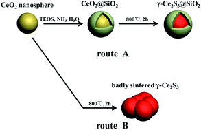 | ||
| Scheme 1 Illustration of the formation of γ-Ce2S3@SiO2 nanoparticles (route A) and badly sintered γ-Ce2S3 (route B). | ||
Experimental
The formation of CeO2 nanoparticles with spherical shape were derived from previous work.19 Similarly, 2.0 g Ce(NO3)3·6H2O was dissolved in 2 ml deionized water by ultrasonic methods. Then, 2 ml CH3COOH and 60 ml glycol were added with stirring for 30 min to form a uniform solution. The mixed solution was sealed in a Teflon-lined stainless steel autoclave and treated for 200 min after the temperature reaches 180 °C. Then the products were separated by centrifugation, washed with water and ethanol repeatedly, and dried at 60 °C in air.SiO2 coated CeO2 was synthesized successfully by sol–gel method.20 Typically, 0.6 g CeO2 was well dispersed in a mixture solution of ethanol by using ultrasonic method, deionized water and 25 wt% concentrated ammonia aqueous stirred for 0.5 h at room temperature. Then, a certain volume of tetraethyl orthosilicate (TEOS) was added into the mixture. After stirring for 6 h at room temperature, the product was filtered and washed with water and ethanol, and then dried at 60 °C for 12 h. The detailed experimental conditions of samples are listed in Table 1.
| sample | CeO2/g | H2O/ml | C2H5OH/ml | NH3·H2O/ml | TEOS/ml |
|---|---|---|---|---|---|
| a0 | 0.6 | 0 | 0 | 0 | 0 |
| b0 | 0.6 | 40 | 160 | 2.5 | 0.5 |
| c0 | 0.6 | 40 | 160 | 5.0 | 1.0 |
| d0 | 0.6 | 40 | 160 | 7.5 | 1.5 |
| e0 | 0.6 | 40 | 160 | 10 | 2.0 |
| f0 | 0.6 | 40 | 160 | 15 | 3.0 |
Series of sulfurized products were obtained by following steps: Firstly, a fine mixture of CeO2@SiO2 and anhydrous Na2CO3 were obtained with a starting mole ratio of Na/Ce = 0.2. Then, the mixture, contained in a mullite boat, was introduced into a high temperature furnace and kept at 800 °C for 2 h. The tube was purged with dried N2 for 20 min before heated. Afterwards, the N2 was bubbled thought a CS2 liquid when the temperature reach to 500 °C.
The powder X-ray diffraction (XRD) measurements were performed with PANalytical/X'Pert PRO diffractometer by using Cu Kα (40 kV, 40 mA) radiation. The morphologies of products were obtained by a transmission electron microscope (TEM, FEI/tecnai F20). Before the TEM test, the samples were dispersed in ethanol by ultrasonication for 5 min in an ultrasonic cleaner. The pigmentary performances of the samples were carried out with a spectrophotometer JENA SPECORD 50/Analytik Jena AG, and D65 illuminant. The thermogravimetric (TG) analysis was recorded on a NETZSCH/STA 409 PC/PG analyzer at a heating rate of 10 °C min−1 from room temperature to 1000 °C.
Results and discussion
Fig. 1 shows the XRD patterns for the series precursors prepared by sol–gel method. All peaks of uncoated (a0) and precoated samples (b0–f0) can be exactly indexed to the cubic CeO2 (JCPDS 41-0013) and no traces of additional peaks belonging to SiO2 were observed. This situation is mainly attributed to the in contrasting environments of crystallinity between amorphous SiO2 and cubic CeO2.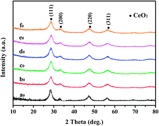 | ||
| Fig. 1 XRD patterns of CeO2@SiO2 samples, the preparation conditions of the samples are listed in Table 1. | ||
XRD patterns for the series sulfurized samples are shown in Fig. 2. It is clearly that the series stabilized γ-Ce2S3 (JCPDS 50-0851) was synthesized successfully by treating corresponding precursors with CS2. Interestingly, when TEOS increasing to 1.0 ml, additional peaks that are essentially identical to the standard data for sulphur (23–0562) were observed (Fig. 2, b1), it reveals that SiO2 was coated successfully by means of sol–gel technology and the SiO2 shell act as an obstacle that prevents the contact and reaction of CeO2 and sulphur. Additionally, with the volume of TEOS increasing, peaks belonging to sulphur were becoming stronger and stronger (Fig. 2, b1–f1), it indicates that the SiO2 shell was getting thicker.
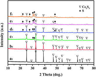 | ||
| Fig. 2 XRD patterns of γ-Ce2S3@SiO2 samples. a1, b1, c1, d1, e1 and f1 are prepared by sulfurizing a0, b0, c0, d0, e0 and f0, respectively. | ||
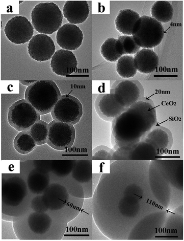
The sizes and morphologies of nanoparticle in samples were examined by TEM (see in Fig. 3). As shown in Fig. 3a, it is clearly that the CeO2 before sulfurizing are nanoparticles with spherical morphology and about 100 nm in size. The SiO2 shells were precoated on the CeO2 nanoparticles with different thickness were synthesized successfully with sol–gel technology.
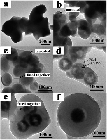
TEM images for series sulfurized samples are given in Fig. 4. As can be seen in Fig. 4a, badly sintered product was obtained when uncoated CeO2 nanoparticles were applied, the formation process belongs to route B is illustrated in Scheme 1. Interestingly, when SiO2 shell is introduced, γ-Ce2S3 nanoparticles with their original morphology and size basically were obtained. It reveals that SiO2 shell can play as a protective layer to prevent sintering process between the nanoparticles. At the same time, unfortunately, under the treatment of high temperature, the SiO2 shell is destroy and fused together (Fig. 4b). But, these results can be improved gradually with the increase of the thickness of SiO2 (Fig. 4c–f). SiO2 coated γ-Ce2S3 nanoparticle with fine core–shell structure was obtained when the SiO2 is thick enough (Fig. 3f, 110 nm). Formation processes of γ-Ce2S3 nanoparticles belongs to route A is illustrated in Scheme 1, when SiO2 layers are introduced.
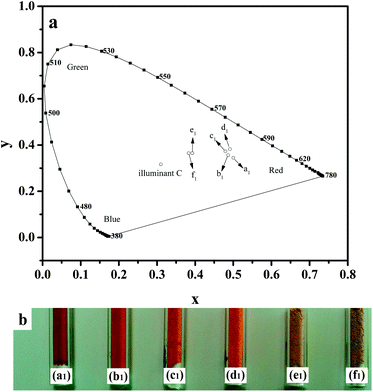
The chromatic coordinates compare to the 1931 CIE Standard Source C and photograph of the samples are shown in Fig. 5. Fig. 5a shows coordinates for a1, b1, c1 and d1 are more closer to the red area than e1 and f1, it is in accord with the fact that the colour of samples from a1 to f1 are red, orange and yellow, respectively, see Fig. 5b. The colorimetric parameters are summarized in Table 2. With the thickness of SiO2 shell increasing, the lightness (L*) of the sulphide powder is increases gradually from 40.38 to 66.73 while the red-green index a* and dominant wavelength are decrease from 34.62 to 9.16 and 602 to 580 nm, respectively. Additionally, products present a stronger value of b* between 22.66 and 43.34, which correspond to yellow-blue index. It is reveals that the introduction of SiO2 can improve the lightness and broaden the colour of the pigments.
| Sample number | CIE (x, y) | L* | a* | b* | Dominant wavelength/nm |
|---|---|---|---|---|---|
| a1 | (0.5001, 0.3447) | 40.38 | 34.62 | 26.33 | 602 |
| b1 | (0.4866, 0.3561) | 47.60 | 32.87 | 30.22 | 596 |
| c1 | (0.4793, 0.3728) | 55.70 | 30.10 | 37.21 | 590 |
| d1 | (0.4913, 0.3823) | 57.47 | 30.82 | 43.34 | 589 |
| e1 | (0.3926, 0.3648) | 63.63 | 11.74 | 23.29 | 582 |
| f1 | (0.3830, 0.3648) | 66.73 | 9.16 | 22.66 | 580 |
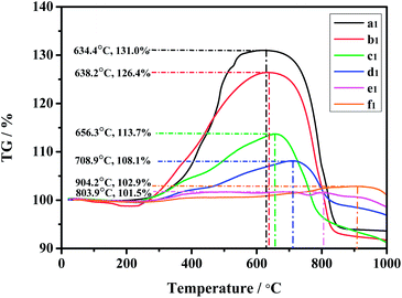
Thermal stability is studied by heat treatment of the samples in air. TG curves for all sulfurized samples are given in Fig. 6. A similar broad peak band clearly exhibited one mass gain and one mass loss processes, it can attribute to the oxidation of the γ-Ce2S3 in air: oxysulfides are the possible intermediates and CeO2 is the final product. The value for corresponding temperature on the curve which follows it is the mass lose process can express thermal stability for sample. Obviously, these values are increasing gradually from sample a1 to f1. Therefore, it seems reasonable to conclude that the thickness of SiO2 can be directly attributed to thermal stability. In addition, The values for corresponding weight (%) are declining basically from sample a1 to f1, except for e1 shows a boarder peak make its value lower than f1. It reveals the content of γ-Ce2S3 in a1 to f1 reducing gradually, this is in good agreement with the XRD and TEM results.
Acid stability was studied by treatment of samples (0.01 g) with hydrochloric acid (10 ml, pH = 0.5). The times which samples lose their original colour (tloc) completely are recorded in Table 3. When coated sample b1 is selected, weak acid stability is observed (tloc = 70 s), the value even smaller than uncoated sample a1 (tloc = 120 s). The reasonable explanation is that b1 has a smaller size and incompletely coated shell. At the same time, with the thickness of SiO2 shell increasing, the acid stability increase dramatically, and the maximum value is 4 h for d1. As an abnormal result, the acid stabilities of e1 and f1 are weaker than d1. It is because that they have a relatively lower content of γ-Ce2S3. All results illustrate that the acid stability of γ-Ce2S3 is improved gradually, when SiO2 layer is introduced.
| Sample | a1 | b1 | c1 | d1 | e1 | f1 |
|---|---|---|---|---|---|---|
| tloc | 120 s | 70 s | 40 min | ≈4 h | ≈3 h | ≈3 h |
Conclusions
In this paper, series of coated γ-Ce2S3 nanoparticles are synthesized successfully by use traditional sulfurization method, when colourless and nontoxic SiO2 layer is introduced. On the one hand, SiO2 can plays as a protective layer to prevent the agglomeration of γ-Ce2S3 nanoparticles. On the other hand, field of application for γ-Ce2S3 pigment may be expended, owing to their unique colour, improved thermal and acid stability.Acknowledgements
The authors are grateful to the financial aid from the National Natural Science Foundation of China (grant no. 20961006), the Inner Mongolia Natural Science Foundation (grant no. 20080404MS0201), and the Inner Mongolia Technology Innovation and Guidance Funds.Notes and references
- J. Flahaut, in Handbook on the Physics and Chemistry of Rare Earths, ed. K. A. Gschneider Jr and L. Eyring, North-Holland, Amsterdam, 1979, vol. 4, p. 1 and references therein Search PubMed.
- M. Guittard and J. Flahaut, in Synthesis of Lanthanide and Actinide Compounds, ed. G. Meyer and L. R. Morss, Kluwer Academic, Dordrecht, 1991, p. 321 and references therein Search PubMed.
- R. Mauricot, P. Gressier, M. Evain and R. Brec, J. Alloys Compd., 1995, 223, 130–138 CrossRef CAS.
- X. Wu, S. Yu, S. Zeng, H. Su, Y. Wang and Z. Cao, J. Chin. Soc. Rare Earths, 2011, 29(6), 714–717 CAS.
- H. Yuan, J. Zhang, R. Yu and Q. Su, J. Rare Earths, 2008, 26(6), 817–820 CrossRef.
- X. Luo, M. Zhang, L. Ma and Y. Peng, J. Rare Earths, 2011, 29(4), 313–316 CrossRef CAS.
- F. Marrot, A. Mosset, J. C. Trombe, P. Macaudière and P. Maestro, J. Alloys Compd., 1997, 259, 145–152 CrossRef CAS.
- P. Li, H. Li and W. Jie, Int. J. Miner., Metall. Mater., 2011, 18(6), 748–752 CrossRef CAS.
- T. Takeshita, K. A. Gschneidner Jr and B. J. Beaudry, J. Appl. Phys., 1985, 57, 4633–4637 CrossRef CAS PubMed.
- J. P. Cotter, J. C. Fitzmaurice and I. P. Parkin, J. Mater. Chem., 1994, 4(10), 1603–1610 RSC.
- S. Roméro, A. Mosset, J. C. Trombe and P. Macaudière, J. Mater. Chem., 1997, 7(8), 1541–1547 RSC.
- P. Li, H. Li and W. Jie, J. Rare Earths, 2011, 29(4), 317–320 CrossRef CAS.
- Y. Ding, J. Gu, T. Zhang, A. X. Yin, L. Yang, Y. W. Zhang and C. H. Yan, J. Am. Chem. Soc., 2012, 134(6), 3255–3264 CrossRef CAS PubMed.
- P. Maestro, European Patent, EP 0203838(A2), 1956.
- C. Thierry, D. Saint, D. Dominique and L. B. Deuil, US Pat., US5401309A, 1995.
- G. Chen, Z. Zhu, H. Liu, Y. Wu and C. Zhu, J. Rare Earths, 2013, 31(9), 891–896 CrossRef CAS.
- Q. Fang and X. Liang, RSC Adv., 2012, 2, 5370–5375 RSC.
- T. Tago, S. Tashiro, Y. Hashimoto, K. Wakabayashi and M. Kishida, J. Nanopart. Res., 2003, 5, 55–60 CrossRef CAS.
- X. Liang, J. Xiao, B. Chen and Y. Li, Inorg. Chem., 2010, 49, 8188–8190 CrossRef CAS PubMed.
- X. Guo, Y. Li, D. Shen, J. Gan, M. Tian and Z. Liu, Appl. Catal., A, 2012, 413–414, 30–35 CrossRef CAS PubMed.
| This journal is © The Royal Society of Chemistry 2014 |

