DOI:
10.1039/C4RA02789B
(Paper)
RSC Adv., 2014,
4, 28229-28237
Direct electrochemistry of cytochrome c immobilized on a graphene oxide–carbon nanotube composite for picomolar detection of hydrogen peroxide
Received
29th March 2014
, Accepted 11th June 2014
First published on 11th June 2014
Abstract
We describe the fabrication of an amperometric biosensor based on cytochrome c (Cyt c) immobilized graphene oxide–multiwalled carbon nanotube (GO–MWCNT) composite on a nano Au modified glassy carbon electrode for trace level detection of H2O2. Morphology and surface characterization of the nanocomposite reveal the successful formation of a highly conducting MWCNT network on the GO surface. Electrochemical impedance studies indicate a lower charge transfer resistance compared to the bare electrode. Cyclic voltammetry studies clearly demonstrate an enhanced direct electrochemistry of Cyt c with a high electron transfer rate constant (ks) value of 3.4 s−1. An amperometric H2O2 biosensor has been fabricated with an excellent current sensitivity of 0.533 μA pM−1 cm−2 and a very low detection limit of 27.7 pM. The fabricated sensor shows exceptional selectivity to H2O2 in the presence of a high concentration of some likely interferents. Moreover, the sensor exhibits high stability with appreciable repeatability and reproducibility.
1. Introduction
Graphene oxide (GO) and its nanocomposites are rapidly emerging as very promising functional nanomaterials because of their facile synthesis, ease of processing and desirable physicochemical properties.1–3 Especially, GO-based nanocomposites have been receiving a lot of attention for use in bioelectrochemical applications as they can provide a hydrophilic and biocompatible microenvironment required for the facile immobilization of various electroactive biomolecules and enzymes.4–6 Functional GO in combination with metal/metal oxide nanoparticles have been applied in electrochemical sensing, electrocatalysis, fuel cells and supercapacitors.7–11 Hybrid materials synthesized by the functionalization of GO with a variety of organic molecules have been reported to exhibit better electrochemical properties.12,13 The excellent biocompatibility of GO-based electrodes makes them amenable for use in electrochemical biosensors. Some reports have already appeared in the literature on the application of GO nanocomposites in DNA and heme protein biosensors.14,15
GO–carbon nanotube (CNT) composites form relatively a new class of hybrid nanomaterials.16,17 The earlier studies were focused mainly on the use of GO for preparing homogeneous dispersion of CNTs in both aqueous and nonaqueous media.18–21 The pioneering work by Cai et al.22 demonstrated the importance of GO–CNT mixing ratio in controlling the resistance and morphology of the resulting hybrid material. Recently, several reports have appeared in literature on the fabrication of the GO–CNT hybrid films by adopting various strategies including self-assembly,23,24 Langmuir–Blodgett assembly,25 and electrostatic interaction.26 A simple coagulation spinning technique has been used to prepare high strength fibres of the GO–CNT nanocomposite.27 Very recently this novel material has been utilized in various electrochemical applications including supercapacitors, batteries, sensors and biosensors.28–33 These studies have demonstrated the superior performance of the nanocomposite as an electrode modifier in comparison to the CNT modified surface.
The electrochemical reduction of H2O2 can be accomplished through direct electron transfer between the electrode and immobilized horse radish peroxidase enzyme.34,35 Alternatively, proteins such as haemoglobin, myoglobin and cytochrome c (Cyt c) containing heme groups, due to their peroxidase like catalytic activity can be used to construct H2O2 biosensors.36–38 However, a major challenge in such heme modified electrodes is that the direct electron transfer between the heme protein and electrode is often not very effective as the redox sites are deeply buried into bulk protein chains. Also the protein can get irreversibly denatured because of its unfavourable orientation to the bare electrode.39 Thus, it is necessary to search for ways to develop new heme-modified electrodes with well-behaved electrochemistry and good stability.
Herein we report the direct electrochemistry of Cyt c immobilized onto the GO–CNT composite and its peroxidase like catalytic activity for the reduction of H2O2. The presence of GO in the nanocomposite provides a hydrophilic and biocompatible environment for the effective immobilization of Cyt c. On the other hand the high conducting network of CNT helps to achieve the direct electron transfer between Cyt c and the electrode. The highly efficient direct electron transfer of the Cyt c immobilized GO–CNT actually aids in the picomolar detection of H2O2 with a remarkable current sensitivity. Such a trace level detection of H2O2 is of prime importance in the fields of bio-imaging, healthcare and terrorism management.40–44
2. Experimental
2.1 Materials and methods
Cytochrome c from horse heart, graphite (powder, <20 μm), multi-walled carbon nanotube (MWCNT), potassium tetrachloro aurate, nafion (Nf) 5 wt% were purchased from Sigma-Aldrich and used as received. 0.5% Nf solution was prepared in ethanol. All reagents were of analytical grade and used as received without any further purification. 0.1 M phosphate buffer solutions (PBS) of pH varying from 1 to 11 were prepared by mixing standard stock solutions of Na2HPO4 and NaH2PO4 and adjusting the pH by the addition of either 0.1 M H3PO4 or 0.1 M NaOH. Prior to each electrochemical experiment, all the solutions were deoxygenated with extra pure N2 gas for about 15 minutes.
The electrochemical measurements were carried out using CHI 611A workstation. A conventional three electrode cell using a glassy carbon electrode (GCE) as the working electrode (area 0.07 cm2), saturated Ag/AgCl as reference electrode and Pt wire as counter electrode was used. Amperometric measurements were performed by an analytical rotator AFMSRX (PINE instruments, USA) with a rotating disc electrode (RDE) having a working area of 0.24 cm2. EIM6ex ZAHNER (Kroanch, Germany) was used for electrochemical impedance spectroscopy (EIS) studies using a frequency range between 100 mHz and 10 kHz at an applied AC voltage of 0.01 V. The morphology and surface topography were examined by a scanning electron microscope (SEM) (VEGA 3 SBU) and an atomic force microscope (AFM) (APE Research Model A100 SGS) respectively.
2.2 Preparation of GO–MWCNT composite
The GO–MWCNT composite was prepared as follows. Graphite oxide prepared by modified Hummer's method45 was ultrasonically exfoliated for 2 h to get GO. About 5 mg of MWCNT was added to 10 mL of an aqueous dispersion of GO (0.5 mg mL−1) and the mixture was subjected to ultrasonication for 2 h to obtain the GO–MWCNT composite. After the removal of undispersed MWCNT and GO by centrifugation, the GO–MWCNT composite was washed in water and dried in oven for whole night and redispersed in water (0.5 mg mL−1). For parallel comparison studies, pristine GO and MWCNT dispersions (0.5 mg mL−1) were prepared in water and DMF solvents, respectively.
2.3 Fabrication of Nf/Cyt c/GO–MWCNT/AuNP/GCE modified electrode
The Cyt c immobilized GO–MWCNT bionanocomposite was formed on a nano Au modified glassy carbon electrode. Au nanoparticles modified GCE (AuNP/GCE) was prepared by cyclic voltammetric deposition in 0.1 M NaNO3 aqueous solution containing 0.25 mM KAuCl4 in the potential range between 0 and +0.9 V at a scan rate of 0.05 V s−1 for 6 cycles. The resulting electrode was rinsed in water. Then the as prepared GO–MWCNT composite (6 μL) was drop coated onto this and dried for 10 min at room temperature to obtain GO–MWCNT/AuNP/GCE. Thereafter, 6 μL of Cyt c (10 mg mL−1 of PBS pH 7) was drop coated onto this and after a standing time of about 30 minutes, the Cyt c/GO–MWCNT/AuNP/GCE electrode was carefully rinsed with water to remove the unadsorbed Cyt c and then dried. At the end, 2 μL of 0.5% Nf was drop coated onto the enzyme modified electrode and dried at room temperature to get the Nf/Cyt c/GO–MWCNT/AuNP/GCE modified electrode. The Nf coating onto the composite film is expected to prevent the leakage of Cyt c from the electrode matrix and thereby improve the stability of the composite film.46 For comparison Nf/Cyt c/GCE, Nf/Cyt c/GO/AuNP/GCE, and Nf/Cyt c/MWCNT/AuNP/GCE modified electrodes were also prepared.
3. Results and discussion
3.1 Morphological and surface characterization
Fig. 1A is the scanning electron microscopy image obtained for the GO–MWCNT/AuNP film which shows the presence of interconnected MWCNTs in tight contact with the GO surface, suggesting a strong interaction between them. The image conveys the presence of a highly percolating porous morphology which will be greatly suitable for enzyme immobilization. The SEM image of the Cyt c immobilized GO–MWCNT/AuNP shown in Fig. 1B is rather different from that before immobilization in that it shows a compact morphology. Typical 2D and 3D AFM images of the GO–MWCNT/AuNP films before and after Cyt c immobilization are shown in Fig. 1C–F. The AFM images before immobilization (1C & 1D) show the presence of non-agglomerated bundles of MWCNTs uniformly dispersed on the GO surface while those after immobilization (1E & 1F) clearly show that the protein molecules densely cover the entire surface of the GO–MWCNT composite film. The height difference between the two films is found to be about 12 nm indicating a multi-layer coverage by Cyt c.
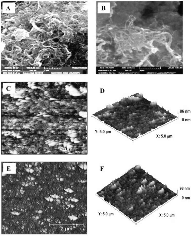 |
| | Fig. 1 SEM images of (A) GO–MWCNT/Au film and (B) Cyt c/GO–MWCNT/Au film and 2D & 3D AFM images of GO–MWCNT/Au (C & D) and Cyt c/GO–MWCNT/Au film (E and F). | |
3.2 Electrochemical impedance spectroscopy (EIS) studies
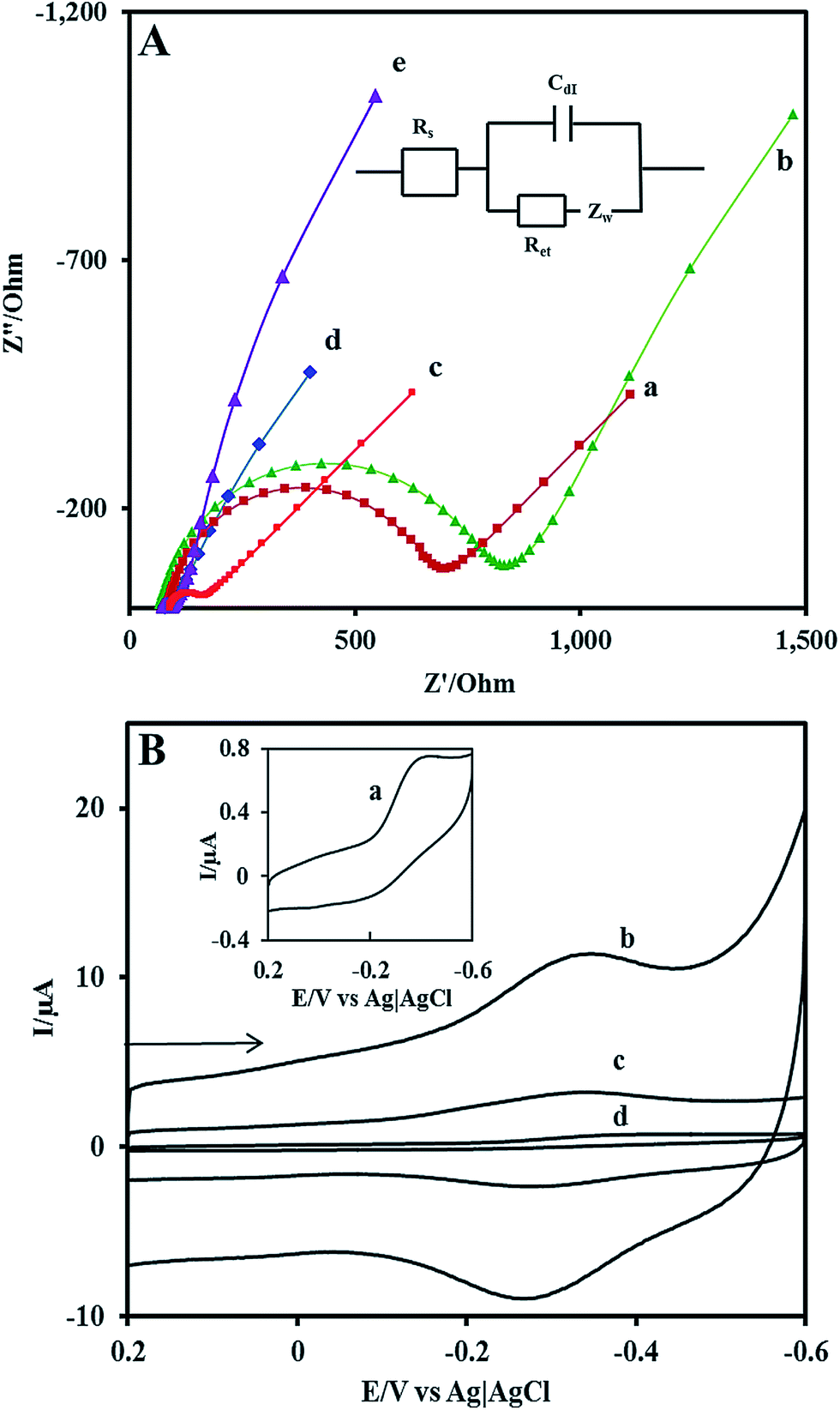
EIS is a powerful method to characterize the electrical properties of the materials and to monitor the changes associated with interfacial properties and thereby allowing to understand the chemical transformation and processes associated with the conductive electrode surface.47 Therefore, in the present study, the EIS technique is applied to derive information about the impedance changes at the electrode/electrolyte interface arising out of electrode modification. All the EIS experiments were performed in an electrolyte solution consisting of an equimolar mixture 5 mM Fe(CN)63−/Fe(CN)64− in 0.1 M KCl. Fig. 2A shows the complex impedance spectra represented as Nyquist plots (Z′ vs. Z′′) for (a) bare GCE, (b)Nf/Cyt c/GCE, (c) AuNP/GCE, (d) GO–MWCNT/AuNP/GCE, and (e) Nf/Cyt c/GO–MWCNT/AuNP/GCE. The impedance data could be fitted to the Randles circuit shown in the inset of Fig. 2, where Rs is electrolyte resistance, Rct is charge transfer resistance, Cdl is double layer capacitance and Zw is Warburg impedance. In the Randles circuit, the Rct and Warburg impedance can be found to be parallel to Cdl which results in a semicircle in the Nyquist plots. The diameter of the semicircle is equal to the Rct value which is indicative of the electron transfer kinetics of the redox probe at the electrode/electrolyte interface. The Nyquist plot of bare GCE exhibits a large semicircle with an Rct value of 641 Ω. The Rct value of Cyt c/GCE (785 Ω) is slightly increased compared to bare GCE which is caused by the nonconductive properties of the biomacromolecule. The AuNP/GCE shows a smaller semicircle than that observed at bare GCE, indicating that the Rct value (84 Ω) has been substantially reduced compared to bare GCE after the deposition of Au nanoparticles. The GO–MWCNT/AuNP/GCE displays almost a similar behaviour with even more reduced Rct of 10 Ω implying that the GO–MWCNT/AuNP/GCE composite provides an excellent conducting surface with accelerated electron transfer. The Rct value of Nf/Cyt c/GO–MWCNT/AuNP/GCE is increased from 10 Ω to 24 Ω suggesting that Cyt c enzyme is successfully immobilized onto the modified electrode surface.
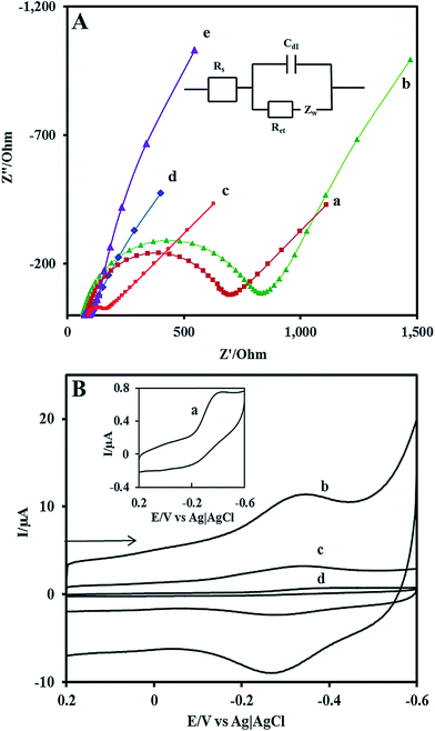 |
| | Fig. 2 (A) EIS of various modified electrodes in 0.1 M KCl solution containing 5 mM Fe(CN)63−/4− at (a) bare GCE (b) Nf/Cyt c/GCE/(c) AuNP/GCE (d) GO–MWCNT/AuNP/GCE and (e) Nf/Cyt c/GO–MWCNT/AuNP/GCE. Inset: Randles equivalent circuit model. (B) Cyclic voltammograms at (a) Nf/Cyt c/GCE (b) Nf/Cyt c/GO–MWCNT/AuNP/GCE (c) Nf/Cyt c/MWCNT/AuNP/GCE (d) Nf/Cyt c/GO/AuNP/GCE in PBS (pH 7) at a scan rate of 0.05 V s−1. | |
3.3 Direct electrochemistry of Cyt c at the Nf/Cyt c/GO–CNT/AuNP modified GCE
Fig. 2B shows the background cyclic voltammograms (CVs) of (a) Nf/Cyt c/GCE, (b) Nf/Cyt c/GO–MWCNT/AuNP/GCE, (c) Nf/Cyt c/MWCNT/AuNP/GCE, (d) Nf/Cyt c/GO/AuNP/GCE in PBS (pH 7) at a scan rate of 0.05 V s−1. The CV of Nf/Cyt c/GCE shows a cathodic peak at −0.36 V with a less prominent anodic peak at about −0.26 V corresponding to the FeIII/II redox couple of Cyt c. The very low current magnitudes of 0.5 μA for Ipc and 0.1 μA for Ipa arise due to its large Rct value. The CV of Nf/Cyt c/GO–MWCNT/AuNP/GCE modified electrode shows well defined redox peaks (Epa at −0.34 V and Epc at −0.28 V) for the FeIII/II redox couple of Cyt c with a peak to peak separation value of (ΔEp) −0.06 V corresponding to a 1e reversible process. The peak current magnitudes (Ipc = 6.1 μA; Ipa = 4.1 μA) are also found to be substantially improved compared to those of Nf/Cyt c/GCE. In order to bring out the role of GO and MWCNT in the direct electrochemistry of Cyt c, the background CVs have been obtained with Nf/Cyt c/MWCNT/AuNP/GCE and Nf/Cyt c/GO/AuNP/GCE as well. The CV of Nf/Cyt c/MWCNT/AuNP/GCE shows a pair of redox peaks with Epa and Epc at −0.33 and −0.25 V respectively with a ΔEp of −0.08 V indicating that the direct electron transfer can also be observed at this modified electrode. However, the peak current values (Ipc = 1.6 μA; Ipa = 0.8 μA) are much lower than those observed at the Nf/Cyt c/GO–MWCNT/AuNP/GCE modified electrode. On the other hand, the CV of Nf/Cyt c/GO/AuNP/GCE does not show any characteristic redox process corresponding to the Cyt c suggesting that the direct electrochemistry has not been achieved at this electrode. This is perhaps due to the poor conductivity of the electrode. A comparison of ΔEp and the ratio of peak currents between Nf/Cyt c/MWCNT/AuNP/GCE and Nf/Cyt c/GO–MWCNT/AuNP/GCE suggests that the kinetics of the direct electrochemistry of Cyt c is rather faster at the latter electrode.
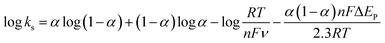
3.4 Effect of scan rate
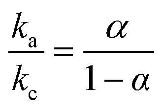
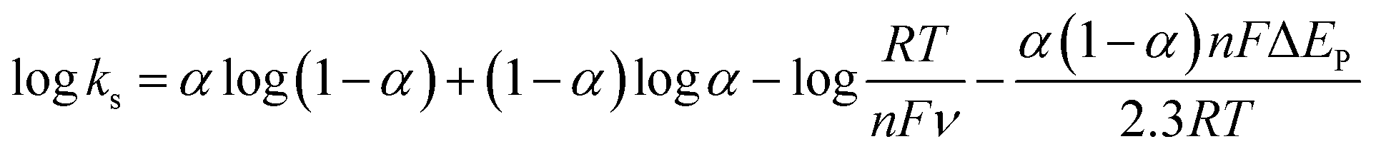
The effect of scan rate on the Cyt c redox process at the Nf/Cyt c/GO–MWCNT/AuNP/GCE electrode is examined in PBS (pH 7). Fig. 3A displays the CVs of the immobilized Cyt c at various scan rates from 0.05 to 1 V s−1. It can be observed that the cathodic and anodic redox peak currents of Cyt c are increased linearly with increase in scan rate (inset of Fig. 3A) indicating that the redox process occurring at the Nf/Cyt c/GO–MWCNT/AuNP/GCE electrode is a surface-controlled electrode process and also confirming that the immobilized state of Cyt c is stable at all scan rates. Also, with increase in scan rates, the oxidation peak shifts to more positive potentials, while the reduction peak shifts to more negative potentials. The anodic (Epa) and cathodic (Epc) peak potentials are plotted against the logarithm of scan rate. Applying Laviron theory,48 the charge transfer coefficient can be calculated for a surface controlled process using eqn (1)| |
 | (1) |
where ka is the slope of the linear plot of Epa vs. log![[thin space (1/6-em)]](https://www.rsc.org/images/entities/char_2009.gif) v (0.069) and kc is the slope of the linear plot of Epc vs. logv (0.091) and α is the charge-transfer coefficient which is calculated to be 0.43. The apparent electron transfer rate constant (ks) can be obtained using eqn (2)
v (0.069) and kc is the slope of the linear plot of Epc vs. logv (0.091) and α is the charge-transfer coefficient which is calculated to be 0.43. The apparent electron transfer rate constant (ks) can be obtained using eqn (2)| |
 | (2) |
 |
| | Fig. 3 (A) Cyclic voltammograms at Nf/Cyt c/GO–MWCNT/AuNP/GCE in PBS (pH 7) at different scan rates in V s−1 (a) 0.05, (b) 0.1, (c) 0.2, (d) 0.3, (e) 0.4, (f) 0.5, (g) 0.6, (h) 0.7, (i) 0.8, (j) 0.9 and (k) 1. Inset: plot of anodic peak current (Ipa) and cathodic peak current (Ipc) against scan rate. (B) Influence of pH on cyclic voltammograms at Nf/Cyt c/GO–MWCNT/AuNP/GCE in PBS of pH (a) 1 (b) 3 (c) 7 (d) 9 and (e) 11. Scan rate: 0.05 V s−1. Inset: plot of formal potential (E°′) against pH. | |
The obtained ks value of 3.4 s−1 for the Nf/Cyt c/GO–MWCNT/AuNP/GCE electrode is found to be higher than that of Cyt c/L-cysteine modified electrode (0.28 s−1),36 Cyt c immobilized colloidal Au modified carbon paste electrode (1.21 s−1)49 and Cyt c adsorbed amine functionalized silica thin films (1.33 s−1).50 This result reveals that the GO–MWCNT nanocomposite is an excellent biocompatible material for the electron transfer of Cyt c.
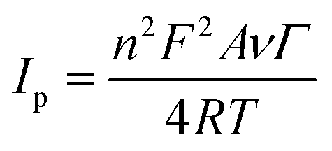
The surface concentration of the Cyt c molecules at the Nf/Cyt c/GO–MWCNT/AuNP/GCE electrode has been estimated based on the slope of Ip vs. ν plot using the Laviron equation eqn (3):51
| |
 | (3) |
where
n,
Ip,
A,
v and
Γ represent the number of electrons transferred in the redox reaction (
n = 1),
Ip is the reduction peak current,
A represents geometric area of the electrode (cm
2),
v is the scan rate (V s
−1) and
Γ is the surface coverage concentration of enzyme on the electrode surface (mol cm
−2) respectively. The constants
F,
R and
T represent Faraday constant (96
485 C mol
−1), gas constant (8.314 J K
−1 mol
−1) and temperature (298 K) respectively. By substituting all the known values in
eqn (3), the surface coverage of enzyme Cyt
c at the GO–MWCNT/AuNP/GCE is calculated to be 1.82 × 10
−9 mol cm
−2, which is higher than the theoretical monolayer coverage of 1.4 × 10
−12 mol cm
−2.
52 Therefore it is inferred that the nanocomposite electrode GO–MWCNT/AuNP/GCE possesses a large number of active sites on its surface facilitating the immobilization of Cyt
c to a greater extent.
3.5 Effect of pH
In order to study the influence of pH on the electrochemical properties of the Nf/Cyt c/GO–MWCNT/AuNP/GCE modified electrode, CVs were recorded in aqueous buffer solutions of various pH in the range between 1 and 11 at a scan rate of 0.05 V s−1 which are shown in Fig. 3B. The results show that the formal potential (E°′) of the redox couple responsible for the direct electrochemistry of Cyt c shifts negatively with increase in pH. A plot of formal potential against pH is linear as exemplified in the inset to Fig. 3B, which indicates that the electron transfer between the immobilized Cyt c and the electrode is accompanied by proton transfer. The obtained slope value of −0.033 V per pH is less than the expected value of −0.059 V per pH for a reversible single electron transfer coupled with a proton. Such a lower slope value was reported for many other heme protein modified electrodes and was attributed to the influence of the protonation states of trans ligands to the heme iron and amino acids around the heme53 or to the protonation of the water molecules coordinated to the central iron atom.54
3.6 Electrocatalytic reduction of H2O2 at Nf/Cyt c/GO–MWCNT/AuNP/GCE
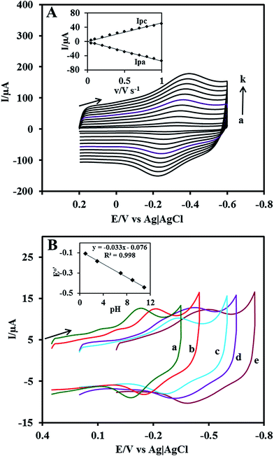
The electrocatalytic ability of the Nf/Cyt c/GO–MWCNT/AuNP/GCE towards the reduction of H2O2 was investigated by cyclic voltammetry. Fig. 4A displays the CVs of Nf/Cyt c/GO–MWCNT/AuNP/GCE modified electrode in PBS of pH 7 with increasing concentration of H2O2 from 0.2 to 2.4 mM (b to l). Curve a in the Fig. 4A shows the background CV of the Nf/Cyt c/GO–MWCNT/AuNP/GCE electrode without any addition of H2O2. From these results, it can be noted that in the absence of H2O2, only the redox peaks of the immobilized Cyt c are observed. Upon an addition of 0.2 mM of H2O2, the cyclic voltammogram shows an increase of reduction peak current and decrease of oxidation peak current. Further additions of H2O2 increased the reduction peak current with concurrent decrease of the oxidation peak current. These results clearly demonstrate the excellent electrocatalytic ability of the Nf/Cyt c/GO–MWCNT/AuNP/GCE towards the reduction of H2O2. The negligible oxidation peak current shows that the oxidation rate of Cyt c by H2O2 is very fast, indicating the pseudo peroxidase activity of the Cyt c immobilized onto the GO–MWCNT composite. The electrocatalytic process can be described by eqn (4) and eqn (5).55| | |
Cyt c–Fe(III) + e− → Cyt c–Fe(II)
| (4) |
| | |
2Cyt c–Fe(II) + 2H+ + H2O2 → 2Cyt c–Fe(III) + 2H2O
| (5) |
 |
| | Fig. 4 (A) Cyclic voltammograms at Nf/Cyt c/GO−MWCNT/AuNP/GCE in 0.1 M PBS (pH 7) (curve a) and in the presence of H2O2 (b) 0.2, (c) 0.4, (c) 0.6, (d) 0.8, (e) 1, (f) 1.2, (g) 1.4 ,(h) 1.6, (i) 1.8, (j) 2, (k) 2.2 and (l) 2.4 mM. Inset: plot of reduction peak current against H2O2 concentration (B) cyclic voltammograms at Nf/Cyt c/GO−MWCNT/AuNP/GCE in PBS (pH 7) containing 1 mM H2O2 at different scan rates in V s−1 (a) 0.1, (b) 0.2, (c) 0.3, (d) 0.4, (e) 0.5, (f) 0.6, (g) 0.7, (h), (i) 0.8, (j) 0.9 and (k) 1. Inset: plot of H2O2 reduction peak current against square root of scan rate. | |
Fig 4B shows the CVs of Nf/Cyt c/GO–MWCNT/AuNP/GCE film modified electrode in PBS of pH 7 containing 1 mM of H2O2 at different scan rates from 0.1 to 1 V s−1 (a to j). The reduction peak current increases linearly with increase in scan rate. A plot of the reduction peak current against the scan rate exhibits a linear relationship and this indicates that the reduction of H2O2 is a diffusion-controlled process.
3.7 Amperometric determination of H2O2
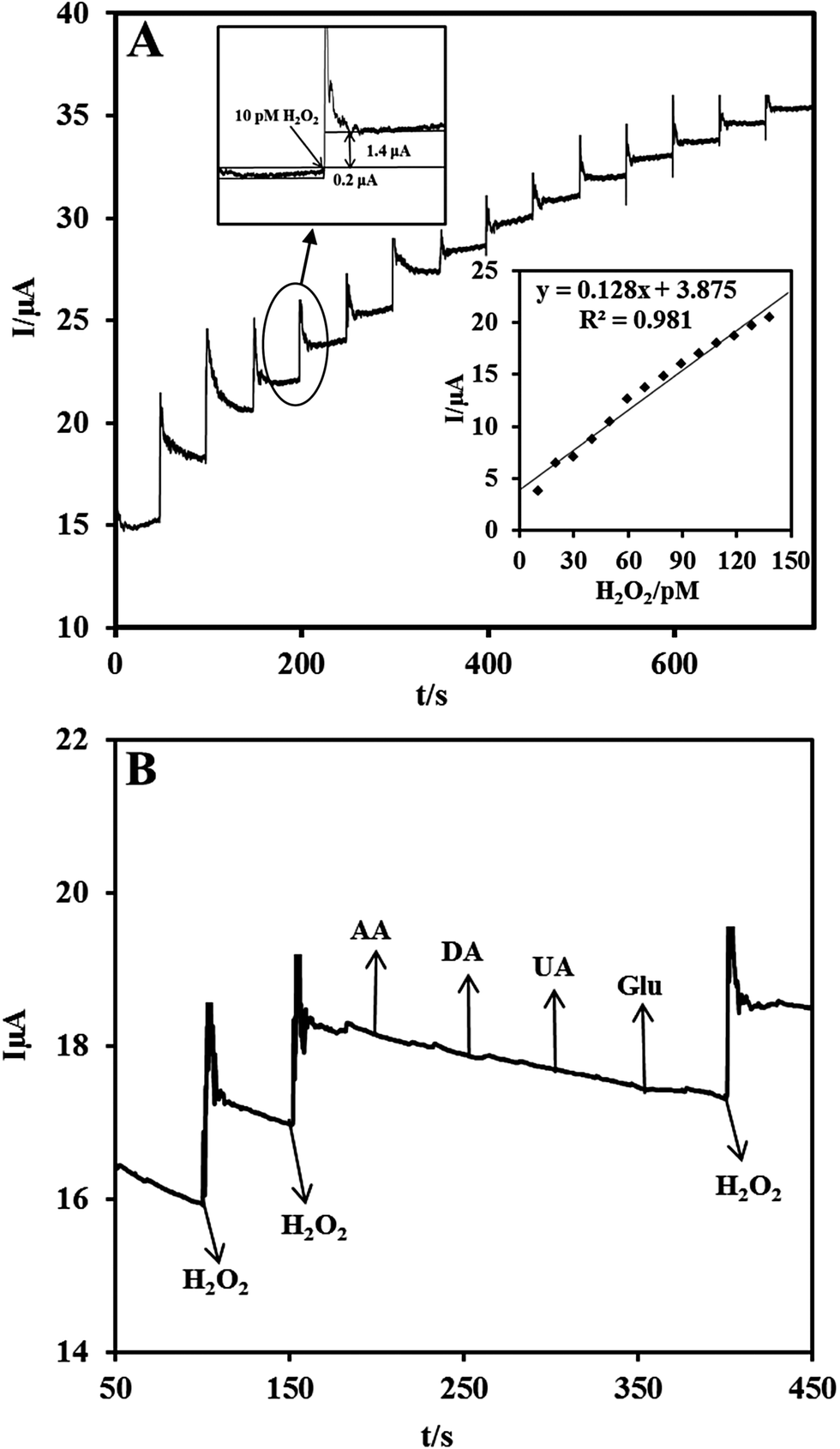
Owing to the excellent electrocatalytic ability of the Nf/Cyt c/GO–MWCNT/AuNP/GCE towards H2O2, an amperometric sensor has been constructed for the trace level detection of H2O2. Fig. 5A shows the amperometric response for each addition of 10 pM concentration of H2O2 at a regular interval of 50 s into deaerated PBS (pH 7) at an applied potential of −0.2 V and an electrode rotation speed of 1000 rpm. The amperometric response current increases linearly with increasing H2O2 concentration from 10 to 140 pM. For every addition of H2O2, the steady state current is reached within 6 s, indicating that the sensor has a short response time. The corresponding calibration curve of the fabricated amperometric H2O2 sensor (inset (bottom) of Fig. 5A) exhibits a linear response with a correlation coefficient of 0.981 and the linear equation can be represented as I (μA) = 0.128 [H2O2] (pM) + 3.875. The limit of detection (LOD) was estimated using the formula in eqn (6):56where sb is the standard deviation obtained from five measurements of the blank signal i.e. 1.182 μA and m is the analytical sensitivity represented by the slope of the calibration plot (0.128 μA pM−1). From these data, the LOD is estimated to be 27.7 pM with a signal-to-noise ratio of 7 (inset (top) of Fig. 5A) and the sensitivity value is determined to be 0.533 μA pM−1 cm−2.
 |
| | Fig. 5 (A) Chronoamperometric response at Nf/Cyt c/GO–MWCNT/AuNP with successive additions of 10 pM H2O2 into a continuously stirred N2 saturated PBS (pH 7). Eapp: −0.2 V. Inset at the bottom: calibration plot for the H2O2 sensor. The upper inset shows the current response of the sensor toward the addition of 10 pM H2O2 for evaluation of signal-to-noise ratio. (B) Chronoamperometric response at Nf/Cyt c/GO–MWCNT/AuNP in 0.1 M PBS (pH 7) with 10 pM of H2O2 and in the presence of 1 μM DA, AA, UA and Glu in Eapp: −0.2 V. | |
It may be mentioned here that the H2O2 sensor performance of the Cyt c immobilized GO–MWCNT nanocomposite based electrode is found to be superior to the other reported Cyt c immobilized modified electrode based biosensors in terms of LOD and current sensitivity as can be seen from Table 1.57−63
Table 1 Comparison of H2O2 chronoamperometric sensor performance at Nf/Cyt c/GO–MWCNT/AuNP electrode with other Cyt c immobilized modified electrodes reported in literature
| Electrode |
Detection limit (nM) |
Linear range (μM) |
Sensitivity/μA pM−1 cm−2 |
Ref. |
| Perylene tetracarboxylic acid. Zeolite. Polyaniline. L-Cystine. P3MT-poly-(3 methylthiophene). Ciprofloxacin. Poly(3,4-ethylenedioxythiophene). |
| Cyt c/PTCAa–graphene/GCE |
3500 |
5–90 |
2.44 × 10⁻⁷ |
57 |
| Cyt c/NaYb/GCE |
320.0 |
8–128 |
2.02 × 10⁻⁷ |
58 |
| Cyt c/MWCNT–PANIc/ITO |
300.0 |
0.5–1500 |
3.20 × 10⁻⁸ |
59 |
| Cyt c/nanoporous Au film |
6300 |
10–12000 |
2.80 × 10⁻⁹ |
60 |
| Cyt c/L-Cysd/P3MTe/MWCNT/GCE |
230.0 |
0.7–400 |
— |
61 |
| Cyt c/MWCNTs/CFf/GCE |
1000 |
2–78 |
— |
62 |
| Cyt c/Graphene–PEDOTg/GCE |
249.0 |
0.5–400 |
— |
63 |
| Nf/Cyt c/GO–CNT/AuNP/GCE |
0.027 |
1 × 10⁻⁵–1.4 × 10⁻⁴ |
0.53 |
This work |
3.8 Interference studies
The selectivity of the proposed biosensor was investigated in the presence of some potentially coexisting interference substances such as uric acid (UA), ascorbic acid (AA), dopamine (DA) and glucose (Glu) in biological systems. Fig. 5B shows the amperometric responses of Nf/Cyt c/GO–MWCNT/AuNP modified GCE for the consecutive additions of (a) 10 pM H2O2, (b) 1 μM DA, (c) 1 μM AA, (d) 1 μM UA and (e) 1 μM Glu at a regular interval of 50 s to PBS of pH 7. At first the nanocomposite bioelectrode showed well defined amperometric responses for the addition of 10 pM H2O2. It is found from the results that dopamine, ascorbic acid, uric acid, and glucose have very low interference effect (<2%) on H2O2 determination. Thus the fabricated Nf/Cyt c/GO–MWCNT/AuNP nanocomposite based sensor exhibits a versatile ability to be devoid of being influenced by such possible interferences coexisting along with H2O2.
3.9 Stability, repeatability and reproducibility studies
The stability of the Nf/Cyt c/GO–MWCNT/AuNP nanocomposite electrode was investigated by recording 100 consecutive cyclic voltammograms in PBS of pH 7 at a scan rate of 0.05 V s−1. It was calculated that about 92% of both the initial cathodic and anodic currents were retained in the 100th cycle, showing that the modified film was highly stable and the immobilised Cyt c was tightly anchored to the modified film. In addition, we found that the nanocomposite electrode retains its 95% (both Ipa and Ipc) of the initial current after one month of its storage under 4 °C in refrigerator. Thus, the fabricated sensor possesses excellent stability due to the strong affinity between Cyt c and GO–MWCNT composite.
The repeatability and reproducibility of the fabricated biosensor was studied by performing cyclic voltammetry in PBS of pH 7 at a scan rate of 0.05 V s−1. The sensor exhibits acceptable reproducibility with a relative standard deviation (R.S.D) of 2.3% for 15 individual measurements and a repeatability of 5.3% for 10 successive measurements. Thus the Nf/Cyt c/GO–MWCNT/AuNP/GCE exhibits acceptable repeatability and reproducibility results.
4. Conclusions
We fabricated a simple H2O2 biosensor based on Nf/Cyt c/GO–MWCNT/AuNP/GCE for the picomolar level detection of H2O2. The presence of GO in the electrode matrix greatly eases the immobilization of Cyt c with a surface coverage value of 1.82 × 10⁻⁹ mol cm−2. Cyclic voltammetry data clearly demonstrate the direct electrochemistry of Cyt c at this nanocomposite electrode. Moreover the large ks value obtained for the redox process shows that the composite film modified electrode significantly enhances the electrical communication between the Cyt c and the electrode surface. The fabricated amperometric sensor exhibits excellent performance with a high sensitivity of 0.533 μA pM−1 cm−2 and very low detection limit of 27.7 pM.
Acknowledgements
This work was supported by Indo-Taiwan exchange programme, Department of Science and Technology, New Delhi and National Science Council and Ministry of Education of Taiwan (Republic of China). Bose Dinesh gratefully acknowledges University Grants Commission for a Meritorious Fellowship.
References
- D. Chen, H. Feng and J. Li, Chem. Rev., 2012, 112, 6027–6053 CrossRef CAS PubMed.
- B. G. Eda and M. Chhowalla, Adv. Mater., 2010, 22, 2392–2415 CrossRef PubMed.
- D. R. Dreyer, S. Park, C. W. Bielawski and R. S. Ruoff, Chem. Soc. Rev., 2010, 39, 228–240 RSC.
- S. Uhm, H. Tuyen and J. Lee, Electrochem. Commun., 2011, 13, 677–680 CrossRef CAS PubMed.
- B. Yuan, X. Zeng, C. Xu, L. Liu, Y. Ma, D. Zhang and Y. Fanc, Sens. Actuators, B, 2013, 184, 15–20 CrossRef CAS PubMed.
- X. Zuo, S. He, D. Li, C. Peng, Q. Huang, S. Song and C. Fan, Langmuir, 2010, 26, 1936–1939 CrossRef CAS PubMed.
- S. Chen, J. Zhu, X. Wu, Q. X. Han and X. Wang, ACS Nano, 2010, 4, 2822–2830 CrossRef CAS PubMed.
- Y. Cui, Q.-Y. Cheng, H. Wu, Z. Wei and B.-H. Han, Nanoscale, 2013, 5, 8367–8374 RSC.
- C.-T. Hsieh, W.-Y. Chen, D.-Y. Tzou, A. K. Roy and H.-T. Hsiao, Int. J. Hydrogen Energy, 2012, 37, 17837–17843 CrossRef CAS PubMed.
- G.-H. Wu, Y.-F. Wu, X.-W. Liu, M.-C. Rong, X.-M. Chen and X. Chen, Anal. Chim. Acta, 2012, 745, 33–37 CrossRef CAS PubMed.
- H. Xiong and B. Jin, J. Electroanal. Chem., 2011, 661, 77–83 CrossRef CAS PubMed.
- N. Karousis, S. P. Economopoulos, E. Sarantopoulou and N. Tagmatarchis, Carbon, 2010, 48, 854–860 CrossRef CAS PubMed.
- A. Österholm, T. Lindfors, J. Kauppila, P. Damlinb and C. Kvarnström, Electrochim. Acta, 2012, 83, 463–470 CrossRef PubMed.
- A. Erdem, M. Muti, P. Papakonstantinou, E. Canavar, H. Karadeniz, G. Congur and S. Sharma, Analyst, 2012, 137, 2129–2135 RSC.
- C. Guo, H. Sun and X. S. Zhao, Sens. Actuators, B, 2012, 164, 82–89 CrossRef CAS PubMed.
- H. X. Kong, Curr. Opin. Solid State Mater. Sci., 2013, 17, 31–37 CrossRef CAS PubMed.
- V. Mani, B. Devadas and S.-M. Chen, Int. J. Electrochem. Sci., 2013, 8, 11641–11660 CAS.
- X. Dong, G. Xing, M. P. C. Park, W. Shi and N. Xiao, Carbon, 2011, 49, 5071–5078 CrossRef CAS PubMed.
- L. Qiu, X. Yang, X. Gou, W. Yang, Z.-F. Ma, G. G. Wallace and D. Li, Chem.–Eur. J., 2010, 16, 10653–10658 CrossRef CAS PubMed.
- L. Tian, M. J. Meziani, F. Lu, C. Y. Kong, L. Cao, T. J. Thorne and Y.-P. Sun, ACS Appl. Mater. Interfaces, 2010, 2, 3217–3222 CAS.
- C. Zhang, L. Ren, X. Wan and T. Liu, J. Phys. Chem. C, 2010, 114, 11435–11440 CAS.
- B. D. Cai, M. Song and C. Xu, Adv. Mater., 2008, 20, 1706–1709 CrossRef.
- J. J. Shao, W. Lv, Q. Guo, C. Zhang, Q. Xu, Q.-H. Yang and F. Kang, Chem. Commun., 2012, 48, 3706–3708 RSC.
- Q. Zhang, S. Yang, J. Zhang, L. Zhang, P. Kang, J. Li, J. Xu, H. Zhou and X.-M. Song, Nanotechnology, 2011, 22, 494010–494017 CrossRef PubMed.
- Q. Zhang, B. Zhang, X. Lin, N. Yousefi, Z.-D. Huang, Z. Li and J.-K. Kim, J. Mater. Chem., 2012, 22, 25072–25082 RSC.
- Y. K. Kim, H. K. Na, S. J. Kwack, S. R. Ryoo, Y. Lee, S. Hong, S. Hong, Y. Jeong and D.-H. Min, ACS Nano, 2011, 5, 4550–4561 CrossRef CAS PubMed.
- R. Wang, J. Sun, G. Lian, C. Xu and J. Zhang, Chem. Commun., 2011, 47, 8650–8652 RSC.
- S. Cheemalapati, S. Palanisamy, V. Mani and S.-M. Chen, Talanta, 2013, 117, 297–304 CrossRef CAS PubMed.
- J. Li, D. Kuang, Y. Feng, F. Zhang, Z. Xu, M. Liu and D. Wang, Microchim. Acta, 2013, 180, 49–58 CrossRef CAS.
- L.-Y. Lin, M.-H. Yeh, J.-T. Tsai, Y.-H. Huang, C.-L. Sun and K.-C. Ho, J. Mater. Chem. A, 2013, 1, 11237–11245 CAS.
- S. Luo, Y. Wu and H. Gou, Ionics, 2013, 19, 673–680 CrossRef CAS.
- C. Wu, X. Huang, X. Wu, L. Xie, K. Yang and P. Jiang, Nanoscale, 2013, 5, 3847–3855 RSC.
- K. Zhang, L. Lu, Y. Wen, J. Xu, X. Duan, L. Zhang, D. Hu and T. Nie, Anal. Chim. Acta, 2013, 787, 50–56 CrossRef CAS PubMed.
- Q. Wang, A. Kromka, J. Houdkova, O. Babchenko, B. Rezek, M. Li, R. Boukherroub and S. Szunerits, Langmuir, 2012, 28, 587–592 CrossRef CAS PubMed.
- Y. Xin, X. F-bing, L. H-Wei, W. Feng, C. D-zhao and W. Z-yang, Electrochim. Acta, 2013, 109, 750–755 CrossRef CAS PubMed.
- Y.-C. Liu, S.-Q. Cui, J. Zhao and Z.-S. Yang, Bioelectrochemistry, 2007, 70, 416–420 CrossRef CAS PubMed.
- M. Wang, Q. Sheng, D. Zhang, Y. He and J. Zheng, Bioelectrochemistry, 2012, 86, 46–53 CrossRef CAS PubMed.
- L. Xie, Y. Xu and X. Cao, Colloids Surf., B, 2013, 107, 245–250 CrossRef CAS PubMed.
- J. J. Feng, G. Zhao, J. J. Xu and Y. H. Chen, Anal. Biochem., 2005, 342, 280–286 CrossRef CAS PubMed.
- J. Benedet, D. Lu, K. Cizek, J. L. Belle and J. Wang, Anal. Bioanal. Chem., 2009, 395, 371–376 CrossRef CAS PubMed.
- R. Chen, L. Zhang, G. Gao, W. Wu, Y. Hu and X. Jiang, J. Biomed. Biotechnol., 2011, 679492 Search PubMed.
- D. Lee, S. J. C. Khaja, J. C. Velasquez-Castano, M. Dasari, C. Sun, J. Petros, W. R. Taylor and N. Murthy, Nat. Mater., 2007, 6, 765–769 CrossRef CAS PubMed.
- R. Schulte-Ladbeck, M. Vogel and U. Karst, Anal. Bioanal. Chem., 2006, 386, 559–565 CrossRef CAS PubMed.
- R. Stolarek, P. Bialasiewicz, M. Krol and D. Nowak, Clin. Chim. Acta, 2010, 411, 1849–1861 CrossRef CAS PubMed.
- W. S. Hummers and R. E. Offeman, J. Am. Chem. Soc., 1958, 80, 1339 CrossRef CAS.
- C. Guo, H. Sun and X. S. Zhao, Sens. Actuators, B, 2012, 164, 82–89 CrossRef CAS PubMed.
- F. Lisdat and D. Schafer, Anal. Bioanal. Chem., 2008, 391, 1555–1567 CrossRef CAS PubMed.
- E. Laviron, J. Electroanal. Chem., 1979, 101, 19–28 CrossRef CAS.
- H. X. Ju, Q. S. Liu, X. B. Ge, F. Lisdat and W. F. Scheller, Electroanalysis, 2002, 14, 141–147 CrossRef CAS.
- X. Zhang, J. Wang, W. Wu, S. Qian and Y. Man, Electrochem. Commun., 2007, 9, 2098–2104 CrossRef CAS PubMed.
- A. J. Bard and R. L. Faulkner, in Electrochemical Methods: Fundamentals and Applications, Wiley, New York, 2nd edn, 2001 Search PubMed.
- R. E. Dickerson, T. Takano, D. Eisenberg, O. B. Kallai, L. Samson, A. Cooper and E. Margoliash, J. Biol. Chem., 1971, 246, 1511–1535 CAS.
- J. J. Feng, G. Zhao, J. J. Xu and Y. H. Chen, Anal. Biochem., 2005, 342, 280–286 CrossRef CAS PubMed.
- J.-Y. Sun, K.-J. Huang, S.-F. Zhao, Y. Fan and Z.-W. Wu, Bioelectrochemistry, 2011, 82, 125–130 CrossRef CAS PubMed.
- A. K. Yagati, T. Lee, J. Min and J.-W. Choi, Colloids Surf., B, 2012, 92, 161–167 CrossRef CAS PubMed.
- G. L. Long and J. D. Winefordner, Anal. Chem., 1983, 55, 712 A CrossRef CAS.
- N. Zhang, X. Lv, W. Ma, Y. Hu, F. Li, D. Han and L. Niu, Talanta, 2013, 107, 195–202 CrossRef CAS PubMed.
- Z. Dai, S. Liu and H. Ju, Electrochim. Acta, 2011, 28, 210–215 Search PubMed.
- K.-P. Lee, A. I. Gopalan and S. Komathi, Sens. Actuators, B, 2009, 141, 518–525 CrossRef CAS PubMed.
- A. Zhu, Y. Tian, H. Liu and Y. Luo, Biomaterials, 2009, 30, 3183–3188 CrossRef CAS PubMed.
- M. Eguilaz, L. Agui, P. Yanez-Sedeno and J. M. Pingarron, J. Electroanal. Chem., 2010, 644, 30–35 CrossRef CAS PubMed.
- S. A. Kumar, S.-F. Wang, C. T. Yeh, H. C. Lu, J. C. Yang and Y. T. Chang, J. Solid State Electrochem., 2010, 14, 2129–2135 CrossRef CAS PubMed.
- G.-X. Wang, Y. Qian, X. X. Cao and X.-H. Xia, Electrochem. Commun., 2012, 20, 1–3 CrossRef CAS PubMed.
|
| This journal is © The Royal Society of Chemistry 2014 |
Click here to see how this site uses Cookies. View our privacy policy here.