Flexible aerogels with interpenetrating network structure of bacterial cellulose–silica composite from sodium silicate precursor via freeze drying process†
Huazheng Saia,
Li Xinga,
Junhui Xiang*a,
Lijie Cui*b,
Jianbin Jiaoc,
Chunlin Zhaoa,
Zhenyou Lia,
Fei Lia and
Ting Zhanga
aCollege of Materials Science & Opto-Electronic Technology, University of the Chinese Academy of Sciences, Yuquan Road 19A, Beijing 100049, China. E-mail: xiangjh@ucas.ac.cn
bCollege of Chemistry and Chemical Engineering, University of the Chinese Academy of Sciences, Yuquan Road 19A, Beijing 100049, China. E-mail: ljcui@ucas.ac.cn
cCollege of Engineering and Information Technology, University of the Chinese Academy of Sciences, Yuquan Road 19A, Beijing 100049, China
First published on 18th June 2014
Abstract
Bacterial cellulose (BC)–silica composite aerogels (CAs) with interpenetrating network (IPN) microstructure are prepared through a permeation sol–gel process followed by freeze drying. The IPN structure is constructed by diffusing the precursor into a three-dimensional (3D) BC matrix followed by permeating the catalyst into the BC network gradually to promote the in situ condensation of precursor to form a SiO2 gel skeleton from outside to inside. The precursor used here is Na2SiO3 instead of traditional tetraethoxysilane. This IPN structure could offer excellent mechanical properties to aerogels, and is essential to prepare flexible aerogels by freeze drying. The compression modulus of CAs could be adjusted in the range of 0.38 MPa to 16.17 MPa. The BC–silica CAs exhibit low density (as low as 0.011 g cm−3), high specific surface area (as high as 534.5 m2 g−1) and low thermal conductivity (less than 0.0369 W m−1 K−1). Furthermore, the contact angle of the hydrophobization modified CAs is as high as 145°. The outstanding hydrophobicity and the large specific surface area endow the hydrophobic CAs with excellent oil absorption capability on the water surface. Moreover, the hydrophobic CAs that had absorbed oil could be washed and recycled.
Introduction
Aerogels are porous solids made by removing the solvent from gels while maintaining the porosity of the gel network. They have an enormous potential to be used in thermal insulation, optics, acoustic insulation, catalysts and absorbents because of their low thermal conductivity, low dielectric constant, large specific surface area and low density.1,2 Unfortunately, the applications of inorganic aerogels in daily life have been restricted due to their inherent fragility and high cost.3,4 Hence, developing an ideal method to prepare aerogels is vitally significant to match the demand of their future applications.Silica aerogel networks are formed by connecting silica nanoparticles. A few methods have been widely studied to ameliorate the microstructure of silica gel skeleton to improve their mechanical strength: increasing the concentration of precursor to increase the number of connecting points between the silica nanoparticles,5,6 or using an aging process to make the silica migrate to the neck regions between two connected silica nanoparticles to thicken the neck regions in the silica gel skeleton.7–9 Recently, Rao et al.10,11 and Kanamori et al.12 used alkyltrialkoxysilane instead of the traditional tetraethoxysilane (TEOS) precursor to endow flexibility to the silica skeleton, because the cross-link density of silica could be decreased (the number of alkoxy groups that can form rigid Si–O–Si bonds after hydrolysis decreased from four to three). Moreover, the copolymerization or cogelation of silanes with an organic polymer has been studied to improve the mechanical properties of silica aerogels.13,14 Especially, Meador et al. have demonstrated that reinforcing silica aerogels by conformally coating the silica gel skeleton with a polymer was a more effective way to improve its mechanical properties.15–18 Their excellent studies improved the strength of aerogels by as much as 2 orders of magnitude while only doubling the density as compared to native silica aerogels. Furthermore, they introduced flexible links [e.g. 1,6-bis(trimethoxysilyl)hexane] into the silica skeleton to reduce the Si–O–Si bonds followed by the conformal coating of polymer.19 Both the flexible links and the isotropic coating endow the aerogels with outstanding flexibility and recovery (they recover nearly 100% of their original size after compression to 25% strain twice). However, they pointed out that the preparation process was fairly involved, and the method of conformally coating the silica gel skeleton with a polymer was required to be streamlined to adapt to commercial scale manufacturing.20
Recently, we have developed a method to construct an interpenetrating network (IPN) of bacterial cellulose (BC) matrix and silica gel skeleton.21 It is different from the work reported in ref. 22 that inorganic nanoparticles absorbed on the matrix network form an isotropic network. Under the confinement effect of the robust three-dimensional (3D) BC matrix, the composite aerogels (CAs) can withstand the safer and cheaper freeze drying process, which always causes the fragile solid inorganic aerogels to crack into small fragments or even powders, to obtain monolithic silica aerogels. Hence, the traditional supercritical drying method, which is expensive and dangerous, could be substituted. Because the microcracks caused from the crystallization of the fluid within the SiO2 gel skeleton could provide enough space to endure a certain deformation, CAs exhibited remarkable flexibility. However, this method, which needs the freeze drying process twice to construct the dried BC matrix and CAs, respectively, is involved and time-consuming. In this work, we ameliorate the synthesis process and obtain BC–silica CAs with freeze drying only once. Especially, the precursor used here is sodium silicate (Na2SiO3) instead of TEOS. Hence, the cost could be largely reduced, and the synthesis process is more environmentally-friendly. Furthermore, the hydrophobization modified CAs show stronger hydrophobicity, because the permeation sol–gel process used here enhances the roughness of the sample surface.
The synthesis of BC–silica CAs based on sodium silicate precursor is illustrated in Fig. 1. First, the pretreated BC hydrogels were immersed into Na2SiO3 solution at 80 °C to make the precursor diffuse into the BC hydrogel 3D network. Then, the hydrogels were taken out and immersed in 2 mol L−1 H2SO4 to catalyze the condensation of SiO32−. Further, the composite gels with IPN structure were washed thoroughly with deionized water. After solvent exchanged with the mixture of deionized water and tert-butanol, the wet gels were dried with a freeze drying method to obtain CAs. CAs were prepared from diffusing the precursor into the wet matrix (i.e. BC hydrogel) followed by catalyzing the condensation of precursor. It is different from our previous work, diffusing the silica alcosols into the dried BC matrix (i.e. BC aerogel) to continue the sol–gel process inside of the BC matrix. This amelioration simplifies the preparation method obviously and promotes the application of aerogels.
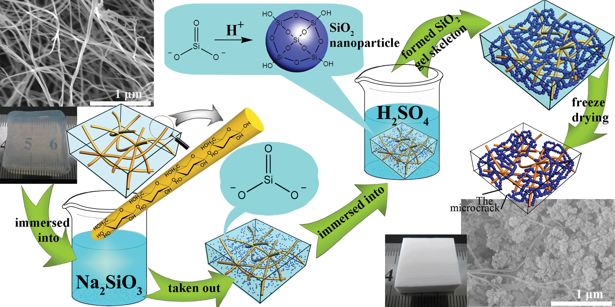 | ||
| Fig. 1 Schematic illustration of the formation mechanism of CAs. (a) SEM (scanning electron microscopy) image and photograph of BC hydrogels 3D network (matrix). (b) SEM image and photograph of BC–silica CAs (SiO2 about 95.9% w/w). Firstly, the Na2SiO3 diffused into the BC hydrogel 3D network. Then, the SiO32− converted into SiO2 nanoparticles (represented by blue balls) as H+ diffused into the BC 3D network, and these nanoparticles assembled with the silica gel skeleton to form the IPN structure with the BC network. Lastly, the wet gels were dried with a freeze drying method to obtain the CAs. | ||
Experimental
Materials
The food Nata-de-coco (i.e. BC hydrogel) was procured from Kuangquan Food Co., Ltd. (Tangshan, China). Sodium silicate (Na2SiO3·9H2O, molar ratio SiO2![[thin space (1/6-em)]](https://www.rsc.org/images/entities/char_2009.gif) :Na2O = 1:1) and tert-butanol were produced by Tianjin Fuchen Chemical Reagents Factory (Tianjin, China). Sulfuric acid (H2SO4), oxalic acid (C2H2O4) and ammonia (NH3·H2O) was bought from Beijing Chemical Reagents Co. (Beijing, China). Methyltrimethoxysilane (MTMS) was purchased from Shanghai Jingchun Reagents Co., Ltd. (Shanghai, China). All reagents were used without further purification.
:Na2O = 1:1) and tert-butanol were produced by Tianjin Fuchen Chemical Reagents Factory (Tianjin, China). Sulfuric acid (H2SO4), oxalic acid (C2H2O4) and ammonia (NH3·H2O) was bought from Beijing Chemical Reagents Co. (Beijing, China). Methyltrimethoxysilane (MTMS) was purchased from Shanghai Jingchun Reagents Co., Ltd. (Shanghai, China). All reagents were used without further purification.
Preparation of BC matrix
BC matrix was prepared from delicious Nata-de-coco (i.e. unpurified BC hydrogels). The unpurified BC hydrogels were immersed in deionized water (4 h) to wash the sugar out. The washed BC hydrogels were heated to 90 °C in a concentrated NaOH solution (6 h). Then the hydrogels were put in a beaker with 100 mL water, and the water was stirred with a magnetic stirrer. The water was changed every 2 hours. After 10 hours, the water was poured off to obtain the semitransparent BC matrix (Fig. 1a).Preparation of silica–BC composite gels
The purified BC matrix (i.e. BC hydrogels) was immersed in different concentrations of Na2SiO3 solution (Table 1) at 80 °C, stirred for 8 h to make the precursor diffuse into the matrix. Then, the gels were taken out and immersed in 2 M H2SO4 for the condensation of SiO32− in the BC matrix for 8 h at ambient temperature. The resulting composite gels were immersed in deionized water to wash the residual H2SO4 and the generated Na2SO4 out from the mesopores of the composite gels.| # | Na2SiO3 solution (% wt) | SiO2 in aerogels (% w/w) | Bulk density (g cm−3) | Surface area (m2 g−1) | Porositya (%) | Thermal cond. (mW m−1 k−1) | Compression modulus (MPa) |
|---|---|---|---|---|---|---|---|
| a The porosity includes the void space caused by crystal growth among the gel skeleton when the gels were frozen.b The pure BC matrix that was prepared from purified BC hydrogels directly via freeze drying. | |||||||
| 0b | 0 | 0 | 0.007 | 129.0 | 99.6 | 29.5 | 0.27 |
| 1 | 2.5 | 36.4 | 0.011 | 268.5 | 99.4 | 30.8 | 0.38 |
| 2 | 5 | 69.5 | 0.023 | 479.5 | 98.8 | 31.5 | 0.52 |
| 3 | 10 | 75.3 | 0.053 | 541.1 | 97.3 | 32.3 | 1.09 |
| 4 | 15 | 86.8 | 0.083 | 534.5 | 95.9 | 33.2 | 2.17 |
| 5 | 20 | 93.7 | 0.111 | 510.2 | 94.6 | 34.0 | 3.70 |
| 6 | 25 | 95.1 | 0.142 | 390.5 | 93.2 | 34.7 | 6.42 |
| 7 | 30 | 95.9 | 0.170 | 386.9 | 91.8 | 35.5 | 9.33 |
| 8 | 35 | 96.5 | 0.199 | 315.7 | 90.4 | 36.2 | 12.14 |
| 9 | 40 | 96.9 | 0.229 | 288.5 | 89.0 | 36.9 | 16.67 |
Freeze drying of silica–BC composite gels
The obtained composite gels were solvent exchanged with a mixture of deionized water and tert-butanol. Then, the gels were precooled for 12 h at −20 °C, followed by freeze drying for 20 h to obtain the dried silica–BC composite aerogels (CAs, Fig. 1b).Hydrophobization modification of the composite aerogels (CAs)
First, the silica sol was prepared from methyltrimethoxysilane (MTMS).10 MTMS (1.44 mL), methanol (5 mL) and oxalic acid (0.01 mol L−1, 0.72 mL) were mixed, stirred for 1 h. After 24 h, 10 M ammonia was added to the system, followed by immersion of the dried silica–BC CAs, stirred for 30 min. The wet gels were taken out from the system, then aged at room temperature (24 h) to make sure the silica–BC aerogel skeleton was adequately modified by the sol prepared from MTMS. After solvent exchanged with tert-butanol, the wet gels were freeze dried to obtain hydrophobic CAs.Characterization
Nitrogen physisorption measurements at 77 K were performed by a Gemini V, Micromeritics (U.S.A.). The Brunauer–Emmett–Teller (BET) analysis from the amount of N2 adsorbed at various relative vapor pressures (six points 0.05 < p/po < 0.3, nitrogen molecular cross-sectional area = 0.162 nm2) was used to determine the surface area. The Barrett–Joyner–Halenda (BJH) analyses were conducted from the adsorption isotherm when the pore-size distribution was investigated. Field-emission scanning electron microscopic (SEM) characterization of the BC matrix and CAs was performed by a Hitachi S-4800 (Japan). Thermogravimetric analysis of the BC matrix was carried out by a NETZSCH STA 449C. The sample was placed in a platinum pan and heated from 25 to 550 °C at a rate of 10 K min−1 under a nitrogen atmosphere. The X-ray diffractometry of the cellulose and cellulose–silica aerogels was performed by a MSAL-XD2 X-ray diffractometer with Ni-filtered Cu Kα radiation (λ = 0.1541 nm) in the range of 5–45° (2θ) at 30 kV and 30 mA. Thermal conductivity of the BC matrix and CAs was measured by a C-Therm TCi thermal conductivity analyzer (Canada) through a transient plate method. All the samples were cut to 5 mm thickness and put on the transient plane source, then a weight was put on the sample to make sure the contact between the sample and the transient plane was complete. The stress–strain curves and the compression modulus were measured by Istron-3365 flexural strength testing systems (America) when all the samples were carefully cut into similar cuboid forms by sharp Gillette razors (Super Gillette Blue Blades, China). The contact angle of CAs with hydrophobization treatment was measured by a contact angle measuring system (JC2000C1, POWEREACH). Bulk densities of the matrix and CAs were calculated by weighing the samples and measuring the volumes. The content of silica in CAs was calculated from the equation,where ρ and ρ0 were the bulk density of the CAs and pure BC matrix, respectively. The porosity of the matrix and CAs was calculated according to the equation,

where ρ, ρs and ρc are the bulk density of CAs, the skeletal density of the pure silica aerogels and the skeletal density of the pure BC matrix, respectively; ωs and ωc are the mass fractions of silica and BC in the composite aerogels, respectively.22 Herein, ρs and ρc were designed to be 2.1 g cm−3 and 1.59 g cm−3.23,24

Results and discussion
Tentative research of the permeation sol–gel process
The gel time of sodium silicate is determined by the pH of sodium silicate, and the gel will form instantaneously if the pH of the solution is adjusted to a suitable range.25,26 It was found that the clear sodium silicate solution (Fig. 2a) would be converted into milky gels (Fig. 2b) as soon as a certain amount of 2 M H2SO4 was added. In this process, the pH value of this system was reduced from over 14 to about 10 by the acid catalyst. This gelation process was completed in a very short time (less than 2 seconds) after the acid was added, which means the precursor is quite sensitive to the catalyst. It is clearly different from the process of preparing silica gels with organic precursor (e.g. TEOS), which often needs several minutes or even a few hours to complete the sol–gel process. Hence, we call this gelation of sodium silicate solution rapid sol–gel process in this paper.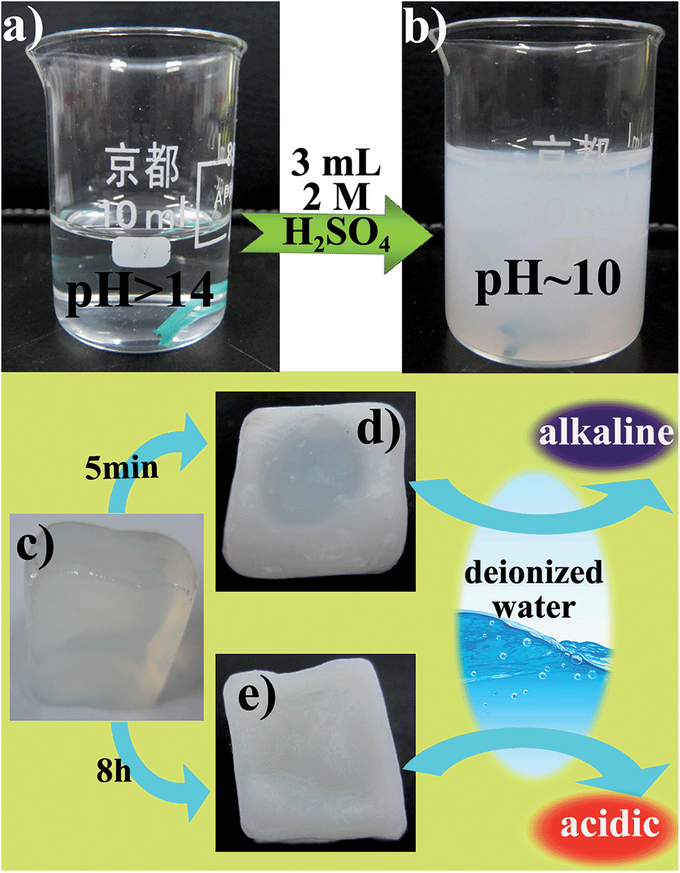 | ||
| Fig. 2 (a) 5 mL Na2SiO3 solution. (b) SiO2 gels that were prepared from (a). (c) The photo of BC matrix with silica Na2SiO3 solution. (d) and (e) are the photos of the samples that were obtained by immersing the BC matrix with silica Na2SiO3 solution in 2 M H2SO4 for 5 min and 8 h, respectively. | ||
Based on the rapid sol–gel process of sodium silica, we suggested a method to construct the IPN structure of BC network and silica gel skeleton, that is, diffusing the acidic catalyst gradually into the BC matrix, which contained Na2SiO3 solution to promote the formation of silica gel skeleton in the BC network. The sol–gel process would occur if the pH value of the Na2SiO3 solution in the BC matrix reduced to a suitable range. It was found that the edges of the semitransparent BC matrix (Fig. 2c) became milky and lost transmittance when it was immersed in 2 M H2SO4 for 5 minutes, but the centre of the simple was still semitransparent and as soft as the initial BC matrix (Fig. 2d). Then, when it was immersed in deionized water for 30 minutes, the water become alkaline (pH > 11). This could be understood because the diffusion of acid was a slow process, and the gelation rate of the Na2SiO3 solution in BC matrix was restricted by the diffusion of H+. Hence, although the precursor is quite sensitive to the acid catalyst, the BC matrix with Na2SiO3 solution should be immersed in the acidic solution for enough time for sufficient diffusion of H+. Hence, when it was immersed in 2 M H2SO4 for 8 h, the whole BC matrix became milky and lost transmittance (Fig. 2e), and the sample became harder as the Na2SiO3 solution in the BC matrix converted into a rigid SiO2 gel skeleton. Then, when it was immersed in the deionized water for 30 minutes, the water become acidic (pH ∼ 1). This means that the acid has thoroughly diffused into the matrix, and the system was changed from strongly alkaline to strongly acidic. In the process, the Na2SiO3 solution in the BC matrix will meet suitable conditions to accomplish the sol–gel when the pH value decreased to the right range. After the sol–gel process was accomplished on the periphery of the sample, the H+ would continually diffuse through the SiO2 gel to the inside of the BC matrix to promote the sol–gel process in the interior of the BC matrix. Hence, it is vital to offer enough time to make sure the H+ has thoroughly diffused into the BC matrix. In addition, it could be speculated that the gelation process of Na2SiO3 was carried out from the outside to the inside of the BC matrix until all the precursor was converted into SiO2 gel skeleton. This process was not only different from the Na2SiO3 solution, which could induce the rapid sol–gel process in the whole solution simultaneously, but also different from the process that constructed the INP structure with TEOS precursor in our previous work.21 The distinctive process in this paper could be called a permeation sol–gel process. Then, the INP structure of BC network and SiO2 gel skeleton has formed. After freeze drying of the silica–BC composite gels, CAs with INP structure were obtained.
Excellent properties and microstructure of bacterial cellulose (BC)–silica composite aerogels (CAs)
It is found that the CAs could withstand freeze drying to keep their integrity (the photograph in Fig. 1b). Generally, the solvent (i.e. water) in the SiO2 hydrogels will crystallize when the hydrogels are precooled. The expansion caused from the crystallization process will destroy the integrity of the stiff SiO2 gel skeleton. Consequently, the preparation of intact silica aerogels with freeze drying used to be a huge challenge.27,28 This problem has been solved by constructing the IPN of BC and SiO2 gel skeleton.21 In this work, we constructed the similar IPN structure (the SEM image in Fig. 1b) of BC and SiO2 gel skeletons through a different way. The similar IPN structure may endow them with similar properties, e.g. integrity and mechanical properties. Although some narrow cracks of silica gel skeleton can be found in CAs, the silica agglomerations with aerogel structure were restricted in certain locations by the 3D BC network to join them together instead of separating each other. The excellent mechanical properties of BC nanofibers (Young's modulus and tensile strength of individual cellulose nanofibers are almost close to those of steel29,30) played an important role in the confinement effect to guarantee the integrity of CAs. Moreover, the BC matrix used as reinforcement was not just the dispersed individual nanofibers, but had a 3D web-like morphology. The joints between BC nanofibers were solidly fixed by large numbers of hydrogen-bonds, which were beneficial for playing the confinement effect of BC matrix. Furthermore, the microcracks caused from the crystallization of the fluid within the SiO2 gel skeleton endow CAs with flexibility so that CAs could maintain their integrity even when compressed about 50% (Fig. S1, ESI†), because these microcracks could provide enough space to allow deformation, and the confinement effect of the robust 3D BC matrix guarantees the integrity of CAs. This mechanism has been discussed in detail in our previous work.21To investigate the pore character of the obtained CAs, N2 adsorption–desorption isotherms of the samples (#1 to #9) were measured (Fig. 3a). The isotherms gradually showed typical hysteresis loops as the content of silica increased, which means the mesopores could effectively form with high concentration of precursor. However, sample #9 prepared from 40% Na2SiO3 did not show the typical hysteresis loops. This phenomenon is understood as the pore size significantly decreased because the much greater SiO2 in CAs compresses the silica gel skeleton and reduces its porosity. The Barrett–Joyner–Halenda (BJH) analyses were conducted from the adsorption isotherm (Fig. 3b). The BJH pore-size distribution also shows the character that the most probable value of pore size increased from 3 nm (#1) to 11 nm (#6) with an increase of the concentration of Na2SiO3, while the value gradually decreased to 3 nm (#9) with much higher concentration of the precursor. These phenomena indicate that the concentration of Na2SiO3 has a remarkable effect on the pore structure of CAs, and it is essential to control the level of precursor to obtain the most suitable microstructure.
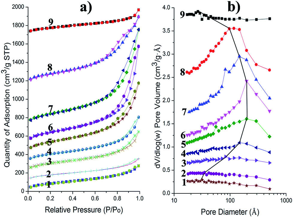 | ||
| Fig. 3 (a) Nitrogen adsorption–desorption isotherms of the CAs (#1 to #9). (b) The relevant BJH pore-size distribution calculated from the adsorption branch of the nitrogen adsorption and desorption isotherms. The most probable values of pore size were linked by a black solid line to highlight the variation tendency of the pore size. It is necessary to illustrate that the curves have been shifted along the Y axis to show these curves clearly. | ||
The SEM images of samples were obtained to confirm how the concentration of precursor influenced the microstructure of CAs. CAs (#3) prepared from Na2SiO3 with low concentration (10%) exhibited a loose lamellar structure with different size adhered to the BC nanofibers, and there was no continuity between these laminations (Fig. 4a and b). Actually, the flakes were the SiO2 aerogel agglomerations, which were composed of silica nanoparticles (Fig. 4b). The lamellar SiO2 aerogel agglomerations were formed under the pressure caused from the crystallization process of the liquid within the gel skeleton. The SiO2 gel skeleton was crushed into laminations, because it was prepared from Na2SiO3 with low concentration, which made the gel skeleton rather weak. On the contrary, CAs (#7) prepared from high concentration (30%) of Na2SiO3 exhibited a continuous SiO2 aerogel structure instead of discrete, loose SiO2 laminations (Fig. 4c and d). Compared with the samples (e.g. #3) prepared from Na2SiO3 with low concentration, more silica nanoparticles and more connecting points between the nanoparticles are formed in the same space. Consequently, the silica gel skeleton is stronger to withstand the pressure caused from the crystallization process. Furthermore, the network of nanofibers were inlaid in the silica gel skeleton to form the IPN structure more effectively (Fig. 4d).
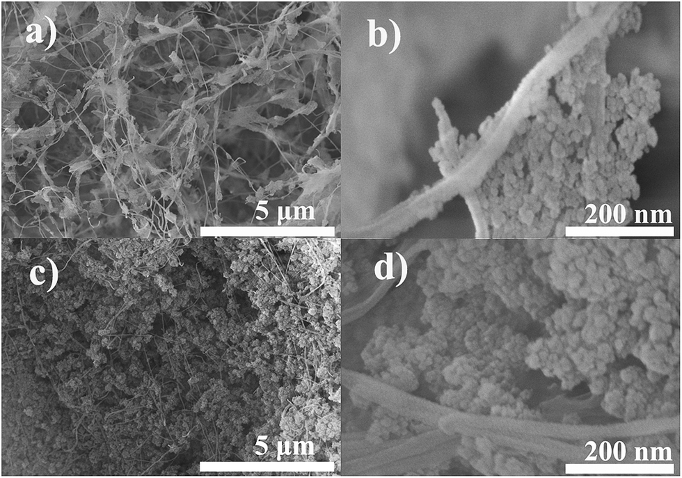 | ||
| Fig. 4 SEM images: (a) and (b) are CAs based on 10% (wt) Na2SiO3 solution. (c) and (d) are CAs based on 30% (wt) Na2SiO3 solution. | ||
The XRD analysis of the obtained CAs showed that the diffraction peaks of BC were gradually covered up by the broad silica peak with the increase of silica content in CAs (Fig. 5). There was no other diffraction peak apart from the corresponding peaks of BC and silica. Based on ref. 22, this phenomenon could be understood as they were just homogeneous combinations of BC and silica, and the combination did not generate new phases or new covalent bonds. Hence, the interaction between BC nanofibers and SiO2 was just hydrogen bonds.
 | ||
| Fig. 5 X-ray diffraction of BC matrix (run 0) and CAs with different ratios of silica (#1 to #9). | ||
Based on above results, it could be speculated that the SiO32− would diffuse into BC hydrogels once they were immersed into the Na2SiO3 solution. Then, SiO32− would convert into SiO2 nanoparticles in the BC network as the H+ gradually diffused into the BC hydrogel. The SiO2 nanoparticles would assemble to form the silica gel skeleton, and the SiO2 nanoparticles adjacent to the BC nanofibers would form hydrogen bonds with the hydroxyl groups of BC. Furthermore, the silica gel skeleton and the BC network construct the IPN structure. After freeze drying, the IPN structure could be conserved effectively when high concentration of Na2SiO3 was used, or the IPN structure would be destroyed by the pressure caused from the crystallization process.
The IPN structure not only enabled CAs withstand the freeze drying to maintain their integrity, but also endowed excellent mechanical properties to CAs. The compression modulus of CAs gradually increased from 0.38 MPa (#1) to 16.67 MPa (#9) upon increasing the ratio of silica (Table 1, and the stress–strain curves are shown in Fig. 6a). The flexible BC matrix was effectively supported by the hard inorganic network to sustain the compression. Hence, the silica aerogel agglomerations in the BC matrix can dramatically affect the mechanical properties of CAs. As shown in the stress–strain curves (Fig. 6), the curves of samples (#1 and #2) prepared with the low concentration of Na2SiO3 nearly coincide with the curve of BC matrix (#0), because the amount and the volume of silica aerogel agglomerations in the BC matrix are too small to support each other when CAs are under external pressure. As the concentration of Na2SiO3 increased, the curves of these samples (#3, #4, #5 and #6) rapidly raised and clearly separated from each other (Fig. 6). Under these conditions, the microcracks between silica aerogel agglomerations were significantly reduced by the increment of the amount and the volume of silica aerogel agglomerations, and the higher concentration of Na2SiO3 made the silica aerogel skeleton stronger to withstand the external pressure rather than deform. However, the difference between the stress–strain curves of CAs (#7, #8 and #9) reduced gradually when we further increased the concentration of Na2SiO3 (Fig. 6). This phenomenon could be understood as the amount and the volume of silica aerogel agglomerations are hard to further increase when the concentration of Na2SiO3 has achieved a high level (≥30% wt), and the increased Na2SiO3 was consumed to reduce the pore size of the silica aerogel (this is in accordance with Fig. 3). Hence, it is easy to adjust the modulus and the flexibility of CAs in a wide range through modulating the concentration of Na2SiO3. Furthermore, CAs could keep their integrity and did not show the true breakpoint under relative high external force because of the confinement effect of the 3D BC network. Based on the IPN structure, the 3D BC network offers an effective confinement to make sure the silica aerogel agglomerates with the SiO2 gel structure in a relative stable location rather than disperse. Consequently, both the SiO2 aerogel agglomeration and 3D BC network endowed CAs with excellent mechanical properties.
 | ||
| Fig. 6 (a) Stress–strain curves of BC matrix (# 0) and BC–silica CAs (# 1 to # 9). (b) log–log plot of compression modulus versus bulk density. The regression coefficient is 0.97. | ||
In addition, the log–log plot of compression modulus versus the bulk density showed that the slope is just 1.78, lower than the slope (about 2.5–4) of traditional pure silica aerogels.31,32 This means the rigidity of CAs increases more slowly as the density increases, compared with traditional aerogels. This may be caused by freeze drying, which introduced microcracks in CAs in this study. These microcracks between silica aerogel agglomerations not only provide enough space for deformation, but also made the silica aerogel agglomerations independent of each other. Hence, the effect of increasing the total amount of silica and the resulting increasing number of connecting points between the silica nanoparticles have been restricted by the microcracks.
CAs exhibited extremely low thermal conductivity, almost the same as traditional native silica aerogels. The thermal conductivity increased from 30.8 mW m−1 k−1 to 36.9 mW m−1 k−1 moderately when the content (mass fraction) of silica increased from 36.4% to 96.9% (Table 1). Consequently, the narrow microcracks and the IPN structure did not destroy the excellent adiabatic performance of CAs. In addition, thermogravimetric analysis curves showed that the temperature of decomposition of the cellulose (BC network) gradually shifted from about 250 °C to about 330 °C (Fig. 7) as the silica content increased. For example, the #2 lost 5% of its weight at 320 °C, lost 10% of its weight at 360 °C and completely degraded at about 410 °C, while the BC matrix (#0) lost 5% of its weight just at 265 °C, lost 10% of its weight at 290 °C and completely degraded at about 380 °C. This difference could be understood as the silica had a stabilizing effect on polymer cellulose.22 Hence, CAs can be used at higher temperatures than many common polymers.
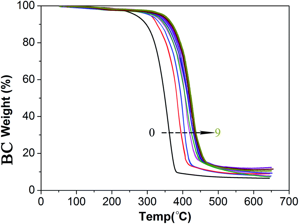 | ||
| Fig. 7 Thermogravimetric analysis (TGA, 10 °C min−1 heating) curves of BC matrix (# 0) and CAs (# 1 to # 9). It is noted that the Y-axis is the BC weight (the pure BC matrix and the BC in CAs), but not the weight of the CAs. Another TGA figure (Y-axis is the weight of the relative sample, not just the BC weight) could be seen in Fig. S2 ESI.† | ||
Hydrophobization modification of composite aerogels (CAs)
Unlike traditional pure silica aerogels, it was found that the dried CAs could maintain their integrity even when immersed into liquid again (Fig. 8a). In addition, the microstructure of CAs did not show obvious change when they were freeze dried again (Fig. S3, ESI†). The IPN structure that had been introduced in CAs was beneficial for withstanding the huge capillary force. Moreover, the micron-size silica aerogel agglomerations could easily deform together with the BC nanofibers to accommodate the pressure caused from the meniscus during the wetting process. Besides, the confinement effect of the robust 3D BC matrix played an important role to prevent the silica aerogel agglomerations separating from each other and dispersing in the liquid when dried CAs were immersed into liquid again.21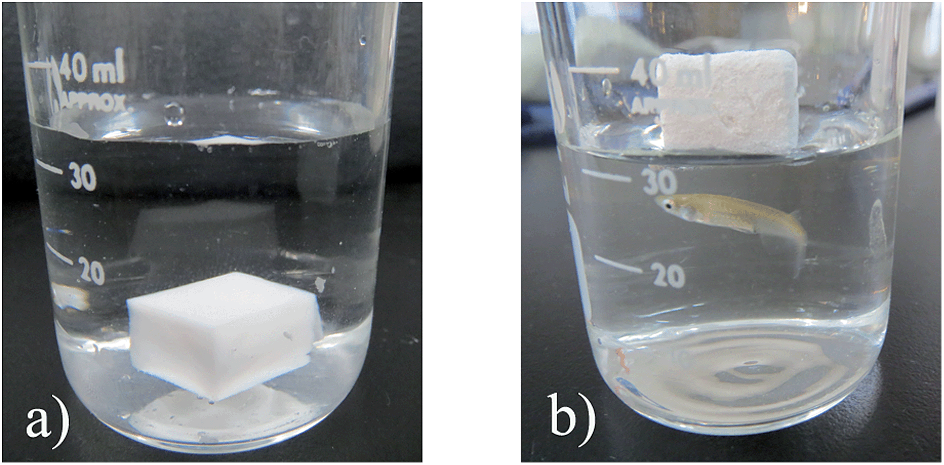 | ||
| Fig. 8 (a) Exhibition of CAs being wetted again (sink in the water). (b) The hydrophobic CAs floating on water. | ||
In addition, it was found that CAs absorbed water and sank into the bottom of the water quickly (less than 10 s) when we put CAs on the water. The excellent absorption property indicated that CAs could be further functionalized in liquid with a hydrophobic modification agent to extend their applications. The CAs (#7) were immersed in the sol prepared from methyltrimethoxysilane (MTMS) followed by freeze drying to accomplish the hydrophobization modification. The modified CAs could float on the water surface (Fig. 8b) because of their hydrophobic property (the contact angle is about 145°) and low density (0.219 g cm−3). Compared with our previous work, the contact angle of the hydrophobic CAs increased from 133° to 145°. This obvious increment could be explained by Wenzel's theory that the liquid follows the roughness of the surface.33–35 At thermodynamic equilibrium, the apparent contact angle of the sample surface and the roughness factor of the given surface have the relationship:
| cosθw = rcosθ |
After hydrophobization modification, the micromorphology of CAs did not change obviously (Fig. S4, ESI†) except that the silica nanoparticles became bigger, and they also showed a large specific surface area (324.5 m2 g−1). Hence, the hydrophobic CAs presented excellent oil absorption capability on the water surface (Fig. 9). The hydrophobic CAs can keep their integrity after absorbing oil and could be removed from the water surface easily, whereas for pure silica aerogels that had absorbed oil, it was difficult to separate the absorbent with oil from the water because the brittle aerogels could not endure the capillary force and cracked seriously when oils were absorbed in the mesopores of the aerogels.36 Interestingly, it was found that the hydrophobic CAs with oil could be conveniently washed by immersing them in an organic solvent (e.g. alcohol) (Fig. 9), and the washed hydrophobic CAs were reusable after freeze drying. Consequently, CAs are beneficial for use as an ideal recyclable material to clean oil spills in a marine environment.
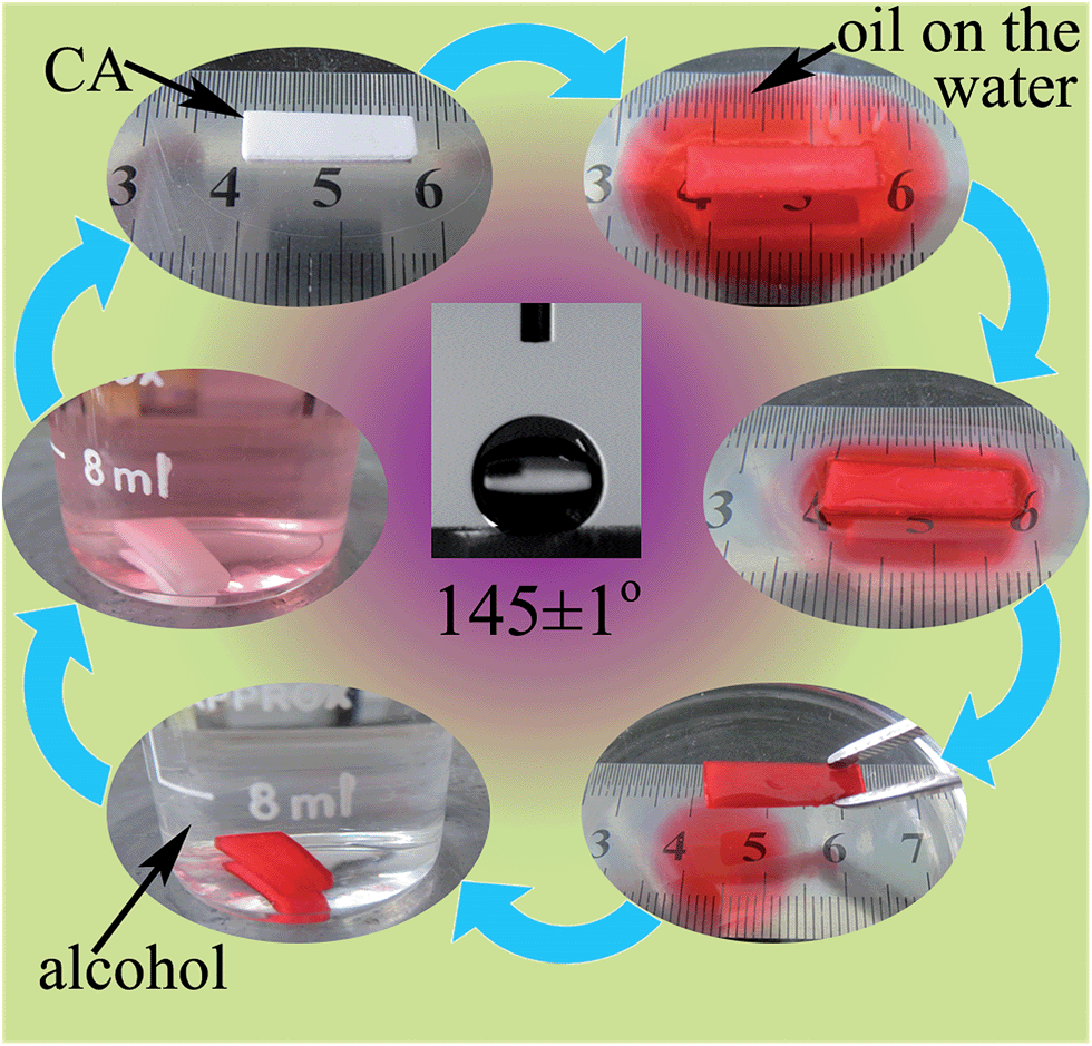 | ||
| Fig. 9 The contact angle of hydrophobic CAs is about 145°, and the photos show the oil absorption capability of the hydrophobic CAs. Herein, 17 mg hydrophobic CAs were placed on the water surface with 150 μL vegetable oil colored with a red dye. Then, the hydrophobic CAs with oil could be washed by alcohol to achieve recycling. | ||
Conclusions
A method to prepare BC–silica CAs with IPN structure has been proposed. Besides excellent mechanical properties, the obtained CAs showed low density, high surface area and low thermal conductivity. Compared with previous methods to construct the IPN of BC matrix and silica aerogel skeleton, the times of freeze drying process has reduced from twice to once to obtain CAs. The efficiency of producing the BC–silica CAs has risen greatly. Furthermore, the precursor used here is sodium silicate instead of TEOS. This improvement not only reduced the cost, but also made the synthesis process more environmentally-friendly. In addition, because the roughness of the sample surface was enhanced by the permeation sol–gel process, the corresponding contact angle increased from 133° to about 145° after the same hydrophobization modification. The outstanding hydrophobicity and the large specific surface area endowed the hydrophobic CAs with excellent oil absorption capability on the water surface. What is more interesting is that the hydrophobic CAs with oil could be washed and recycled. In conclusion, the new method to prepare CAs with excellent properties by a non-supercritical drying process is beneficial for promoting the utilization of aerogels.Acknowledgements
This work was supported by the National Basic Research Program of China (973 Program) with no. 2011CB706900, the National Nature Science Foundation of China (no. 50872149 and 50502003), the Scientific Research Foundation for Returned Scholars within the Ministry of Education of China, and the President Foundation of the Graduate University of the Chinese Academy of Sciences.Notes and references
- N. Hüsing and U. Schubert, Angew. Chem., Int. Ed., 1998, 37, 22–45 CrossRef.
- A. C. Pierre and G. M. Pajonk, Chem. Rev., 2002, 102, 4243–4266 CrossRef CAS PubMed.
- L. Martin, J. O. Osso, S. Ricart, A. Roig, O. Garcia and R. Sastre, J. Mater. Chem., 2008, 18, 207–213 RSC.
- D. J. Boday, P. Y. Keng, B. Muriithi, J. Pyun and D. A. Loy, J. Mater. Chem., 2010, 20, 6863–6865 RSC.
- J. Fricke, J. Non-Cryst. Solids, 1988, 100, 169–173 CrossRef CAS.
- J. Groβ and J. Fricke, Nanostruct. Mater., 1995, 6, 905–908 CrossRef.
- G. Reichenauer, J. Non-Cryst. Solids, 2004, 350, 189–195 CrossRef CAS PubMed.
- R. A. Strøm, Y. Masmoudi, A. Rigacci, G. Petermann, L. Gullberg, B. Chevalier and M. A. Einarsrud, J. Sol-Gel Sci. Technol., 2007, 41, 291–298 CrossRef PubMed.
- F. He, H. Zhao, X. Qu, C. Zhang and W. Qiu, J. Mater. Process. Technol., 2009, 209, 1621–1626 CrossRef CAS PubMed.
- A. V. Rao, S. D. Bhagat, H. Hirashima and G. M. Pajonk, J. Colloid Interface Sci., 2006, 300, 279–285 CrossRef CAS PubMed.
- D. Y. Nadargi, S. S. Latthe, H. Hirashima and A. V. Rao, Microporous Mesoporous Mater., 2009, 117, 617–626 CrossRef CAS PubMed.
- K. Kanamori, M. Aizawa, K. Nakanishi and T. Hanada, Adv. Mater., 2007, 19, 1589–1593 CrossRef CAS.
- S. J. Kramer, F. RubioAlonso and J. D. MacKenzie, Mater. Res. Soc. Symp. Proc., 1996, 435, 295–300 CrossRef CAS.
- B. M. Novak, D. Auerbach and C. Verrier, Chem. Mater., 1994, 6, 282–286 CrossRef CAS.
- M. A. B. Meador, C. M. Scherzer, S. L. Vivod, D. Quade and B. N. Nguyen, ACS Appl. Mater. Interfaces, 2010, 2, 2162–2168 CAS.
- M. A. B. Meador, A. S. Weber, A. Hindi, M. Naumenko, L. McCorkle, D. Quade, S. L. Vivod, G. L. Gould, S. White and K. Deshpande, ACS Appl. Mater. Interfaces, 2009, 1, 894–906 CAS.
- M. A. B. Meador, L. A. Capadona, L. McCorkle, D. S. Papadopoulos and N. Leventis, Chem. Mater., 2007, 19, 2247–2260 CrossRef CAS.
- M. A. B. Meador, E. F. Fabrizio, F. Ilhan, A. Dass, G. H. Zhang, P. Vassilaras, J. C. Johnston and N. Leventis, Chem. Mater., 2005, 17, 1085–1098 CrossRef CAS.
- B. N. Nguyen, M. A. B. Meador, M. E. Tousley, B. Shonkwiler, L. McCorkle, D. A. Scheiman and A. Palczer, ACS Appl. Mater. Interfaces, 2009, 1, 621–630 CAS.
- J. P. Randall, M. A. B. Meador and S. C. Jana, ACS Appl. Mater. Interfaces, 2011, 3, 613–626 CAS.
- H. Sai, L. Xing, J. Xiang, L. Cui, J. Jiao, C. Zhao, Z. Li and F. Li, J. Mater. Chem. A, 2013, 1, 7963–7970 CAS.
- J. Cai, S. Liu, J. Feng, S. Kimura, M. Wada, S. Kuga and L. Zhang, Angew. Chem., Int. Ed., 2012, 51, 2076–2079 CrossRef CAS PubMed.
- N. Hüsing, U. Schubert, R. Mezei, P. Fratzl, B. Riegel, W. Kiefer, D. Kohler and W. Mader, Chem. Mater., 1999, 11, 451–457 CrossRef.
- L. Heath and W. Thielemans, Green Chem., 2010, 12, 1448–1453 RSC.
- R. C. Merrill and R. W. Spencer, J. Phys. Colloid Chem., 1950, 54, 806–812 CrossRef CAS.
- K. S. W. Sing and J. D. Madeley, J. Appl. Chem., 1953, 3, 549–556 CrossRef CAS.
- A. Bisson, A. Rigacci, D. Lecomte, E. Rodier and P. Achard, Drying Technol., 2003, 21, 593–628 CrossRef CAS PubMed.
- J. L. Gurav, I.-K. Jung, H.-H. Park, E. S. Kang and D. Y. Nadargi, J. Nanomater., 2010, 2010, 1–11 CrossRef PubMed.
- H. Yano, J. Sugiyama, A. N. Nakagaito, M. Nogi, T. Matsuura, M. Hikita and K. Handa, Adv. Mater., 2005, 17, 153–155 CrossRef CAS.
- S. Iwamoto, W. Kai, A. Isogai and T. Iwata, Biomacromolecules, 2009, 10, 2571–2576 CrossRef CAS PubMed.
- J. Groβ and J. Fricke, Nanostruct. Mater., 1995, 6, 905–908 CrossRef.
- T. Woignier, J. Reynes, A. H. Alaoui, I. Beurroies and J. Phalippou, J. Non-Cryst. Solids, 1998, 241, 45–52 CrossRef CAS.
- X. M. Li, D. Reinhoudt and M. Crego-Calama, Chem. Soc. Rev., 2007, 36, 1350–1368 RSC.
- R. N. Wenzel, Ind. Eng. Chem., 1936, 28, 988–994 CrossRef CAS.
- M. Miwa, A. Nakajima, A. Fujishima, K. Hashimoto and T. Watanabe, Langmuir, 2000, 16, 5754–5760 CrossRef CAS.
- J. L. Gurav, A. V. Rao, D. Y. Nadargi and H.-H. Park, J. Mater. Sci., 2010, 45, 503–510 CrossRef CAS PubMed.
Footnote |
| † Electronic supplementary information (ESI) available: The photograph of the CAs which were compressed about 50%, TGA analysis curve, the SEM images of CAs (# 7) after being wetted and dried again, the SEM images of CAs (# 7) after hydrophobization treatment. See DOI: 10.1039/c4ra02752c |
| This journal is © The Royal Society of Chemistry 2014 |