Z-scheme photocatalytic hydrogen production over WO3/g-C3N4 composite photocatalysts†
Hideyuki Katsumata*a,
Yusuke Tachia,
Tohru Suzukib and
Satoshi Kanecoa
aDepartment of Chemistry for Materials, Graduate School of Engineering, Mie University, Tsu, Mie 514-8507, Japan. E-mail: hidek@chem.mie-u.ac.jp; Fax: +81-59231-9425; Tel: +81-59231-9425
bEnvironmental Preservation Center, Mie University, Tsu, Mie 514-8507, Japan
First published on 2nd May 2014
Abstract
WO3/g-C3N4 composite photocatalysts were prepared by a simple calcination method and H2 production activity of these composites was evaluated. The photocatalytic activity of the composites highly depended on WO3 content. The enhanced photocatalytic activity could be ascribed to the Z-scheme mechanism, which results in the efficient charge separation.
As a typical metal free inorganic semiconductor, graphitic C3N4 (g-C3N4) has attracted intensive attention for H2 generation,1 pollutant degradation2 and CO2 reduction.3 It is well-known that the band gap of g-C3N4 is about 2.7 eV, which can absorb visible light up to 460 nm.4 Furthermore, the CB minimum (−1.12 eV vs. NHE) of g-C3N4 is extremely negative, so photo-generated electrons should have high reduction ability. However, the photocatalytic efficiency of the pure g-C3N4 is limited by the high recombination rate of its photo-generated electron–hole pairs.5 One of the techniques for increasing the separation efficiency of photo-generated electron–hole pairs is to form a composite photocatalyst using two kinds of semiconductors. Suitable matching of the band levels of the conduction and valence bands in the two semiconductors offers appropriate driving forces to separate and transfer photo-generated electron–hole pairs.6 To improve g-C3N4 photocatalytic activity, various semiconductor/g-C3N4 composite photocatalysts have been reported, such as ZnO,7 TiO2,8 Ag3PO4,9 AgBr,10 Bi2WO6,11 MoS2,12 etc., and used for the photodegradation of organic dyes in solution. However, the photocatalytic H2 production over semiconductor/g-C3N4 composite photocatalysts has been proposed in limited reports.13
On the other hand, studies have shown that WO3 is a visible-light responsive photocatalyst with a relatively narrow band-gap energy (2.4–2.8 eV) and a VB potential similar to that of TiO2.14 Therefore, the oxidizing power of holes in the VB of WO3 and TiO2 are considered to be almost the same. However, pure WO3 is not an efficient photocatalyst because of its low CB level, which limits the photocatalyst's ability to react with electron acceptors such as oxygen.15 The low CB level also increases the recombination of photo-generated electron–hole pairs leading to lower photocatalytic activity. Many attempts have been made to improve the photocatalytic activity of WO3, such as noble metal loading16 and coupling with other semiconductors.17 In our previous study, the activity of WO3 particles could be significantly improved by the binary loading of Ag and CuO as cocatalysts.18 Among them, studies have confirmed that WO3 is a good candidate for synthesizing semiconductor heterojunctions with higher photocatalytic activity. As WO3 and g-C3N4 are both visible-light-driven photocatalysts, after the polymeric g-C3N4 photocatalyst being combined with WO3 the obtained WO3/g-C3N4 composite may be a promising candidate for efficient photocatalytic activity under solar light irradiation. However, there are a few reports on the photocatalytic activity evaluation of WO3/g-C3N4 composite.19,20 Furthermore, to the best of our knowledge, there are no reports on the application of WO3/g-C3N4 composite photocatalysts for H2 production from aqueous solution, and no attention has been paid to the photocatalytic mechanism of the composite-catalysed reaction, which has remained unclear to date.
In this paper, different ratios of WO3/g-C3N4 composite photocatalysts were synthesized via the calcination process. The photocatalysts were characterized by various techniques such as powder X-ray diffraction (XRD), scanning electron microscopy (SEM), transmission electron microscopy (TEM), UV-visible diffuse reflectance spectra (DRS), and so on. The photocatalytic activity was evaluated by H2 production from triethanolamine (TEA) aqueous solution under artificial solar light. The separation mechanisms of photo-excited carriers for the composite photocatalysts were also proposed on the basis of the results for the photoluminescence (PL) analysis.
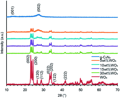
The XRD patterns of WO3/g-C3N4 composites, g-C3N4 and WO3 are shown in Fig. 1. For pure g-C3N4, two broad diffraction peaks around 27.5 and 13.0° were observed, corresponding to the (002) and (100) diffraction planes, respectively. The former, which corresponds to the interlayer distance of 0.325 nm, is attributed to the long-range interplanar stacking of aromatic units; the latter with a much weaker intensity, which corresponds to a distance d = 0.681 nm, is associated with interlayer stacking.1 For WO3/g-C3N4 composites, the XRD patterns reveal a coexistence of WO3 and g-C3N4. The peak intensities of g-C3N4 rapidly decreased with increasing the WO3 contents. It is difficult to confirm the diffraction peaks of g-C3N4 in the XRD pattern of the 30 wt% WO3/g-C3N4 sample. The XRD pattern of WO3 could be indexed as the monoclinic structure. These results along with FTIR spectra (Fig. S1†) and XPS spectra (Fig. S2†) showed clearly that WO3/g-C3N4 composite photocatalysts could be synthesized by the calcination method.
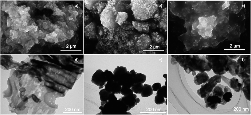
Fig. 2 shows SEM and TEM images of g-C3N4, WO3 and 10 wt% WO3/g-C3N4 composite samples. It is clearly seen in Fig. 2a and d that the morphology of g-C3N4 was smooth, thin and flat sheets. In addition, a typical porous morphology of g-C3N4 powders was exhibited.21 From Fig. 2b and e, WO3 showed aggregated particles with the particle size of 20–150 nm. In the composite sample, WO3 particles were sparsely observed onto the g-C3N4 surface. WO3 particles did not agglomerate and were directly attached to the surface of g-C3N4. With increasing WO3 content, a large number of WO3 particles were observed on the g-C3N4 surface (Fig. S3a–c†). Further, HRTEM observation was conducted to investigate the interfacial structure of the composite sample (Fig. S3d†). The (020) lattice fringe of monoclinic WO3 (0.375 nm) was clearly observed in the HRTEM image. The gray area can be ascribed to g-C3N4. From the SEM, TEM and HRTEM analyses, it can be concluded that the heterojunction structure was formed in the composite.
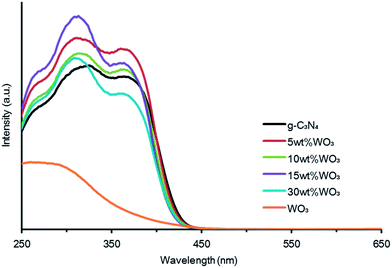
The UV-vis DRS of g-C3N4, WO3 and all composite photocatalysts are shown in Fig. 3. For all samples, the optical absorption edge was estimated to be at around 450 nm. The composite samples displayed better photon absorption than both WO3 and g-C3N4 because the composites would have high crystallinity due to the calcination at 450 °C during the composite photocatalysts preparation. The band gap can be estimated from the following equation:
| αhν = A(hν − Eg)n/2 |
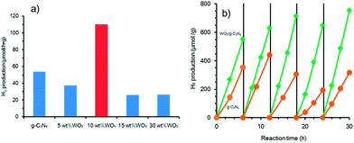
The photocatalytic H2 production over the all samples is shown in Fig. 4a. It revealed that the loading of WO3 greatly influenced the photocatalytic performance of g-C3N4. The H2 production rate over g-C3N4 was 54 μmol h−1 g−1. As a comparison, the composite photocatalysts showed that the H2 production rates were lower than that on g-C3N4 except for 10 wt% WO3/g-C3N4 photocatalyst in which the H2 production rate was 110 μmol h−1 g−1, i.e., the photocatalytic activity of this composite was about 2 times higher than that of g-C3N4. However, the photocatalytic activity of the mechanical mixture of WO3 and g-C3N4 sample with 10 wt% WO3 content (60 μmol h−1 g−1) was almost the same as that of pure g-C3N4. The photocatalytic activity of 10 wt% WO3/g-C3N4 composite was also evaluated under visible light irradiation (>420 nm). As a result, the H2 production rate over 10 wt% WO3/g-C3N4 (66 μmol h−1 g−1) was higher than that of g-C3N4 (27 μmol h−1 g−1) under visible light irradiation. The apparent quantum efficiencies at 405 nm were 0.34 and 0.90% for g-C3N4 and 10 wt% WO3/g-C3N4, respectively.
Fig. 4b shows the time courses of H2 production obtained over g-C3N4 and 10 wt% WO3/g-C3N4 samples under light irradiation. For both samples, the production of H2 steadily increased with prolonged time of light irradiation. However, the photocatalytic activity of g-C3N4 for H2 production gradually decreased during the photocatalytic reaction and a total H2 production was about 1.6 mmol g−1 (36 mL g−1) after 30 h. On the other hand, a total of 3.3 mmol g−1 H2 gas (74 mL g−1) was produced over 10 wt% WO3/g-C3N4, and no obvious deactivation of the composite photocatalyst was found, suggesting the good stability of WO3/g-C3N4 as an organic–inorganic composite photocatalyst for solar H2 production. Furthermore, no changes of the composite sample after photocatalytic reaction were observed in XRD pattern and TEM image (Fig. S5†).
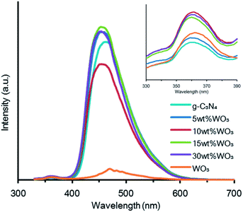
To understand the higher photocatalytic activity of 10 wt% WO3/g-C3N4 relative to other composites, g-C3N4 and WO3, the PL spectra of the samples at 270 nm were recorded (Fig. 5). It is clear that the PL spectra of the composite and g-C3N4 photocatalysts have a strong emission peak at around 450 nm, which could be related to the recombination of the photo-excited electron–hole of g-C3N47,11,22 while a weak emission peak at around 460 nm of WO3 was assigned to localized state in the band gap due to oxygen vacancies or defects.23 From Fig. 5, it can be seen that the PL intensities of the 5, 15 and 30 wt% WO3/g-C3N4 photocatalysts exhibited the stronger emission than that of the pure g-C3N4, suggesting that the recombination of the photo-excited electron–hole on the g-C3N4 photocatalyst surface is higher. On the contrary, the PL intensity of 10 wt% WO3/g-C3N4 composite photocatalyst was lower than that of pure g-C3N4, which means that the recombination of the photo-excited electron–hole of the composite photocatalyst was lower than pure g-C3N4. It indicates that when the amount of WO3 is suitable (10 wt%), the recombination of the photo-excited electron–hole on the g-C3N4 surface is suppressed. However, 10 wt% WO3/g-C3N4 showed the highest PL intensity at around 360 nm among the all samples examined (inset of Fig. 5). The peak around at 360 nm was assigned to the electron–hole recombination on the WO3 surface.23 Therefore, the recombination of the charge carriers on the interface of 10 wt% WO3/g-C3N4 in the composite photocatalyst would be higher than that of pure WO3. The PL results are agreement with the results of photocatalytic H2 production onto WO3/g-C3N4 composite photocatalysts. It means that higher and lower PL intensities at 360 and 450 nm indicate a higher photocatalytic activity in the experimental conditions. The higher PL intensities at 360 nm of the samples would be attributed to the higher recombination rate between photo-excited electrons in the CB of WO3 and photo-excited holes in the VB of g-C3N4 on the interface of the composite, suggesting that rich electrons in the CB of g-C3N4 and holes in the VB of WO3 participate in the reduction reaction of H+ and the oxidation of TEA, respectively. As a result, the charge separation could be promoted on the 10 wt% WO3/g-C3N4 composite, leading to the higher photocatalytic activity of the composite photocatalyst. Based on these results, it could be concluded that the WO3/g-C3N4 system is a typical Z-scheme photocatalyst.
On the basis of the above results, the photocatalytic mechanism for the WO3/g-C3N4 composite sample is tentatively proposed and schematically illustrated in Fig. 6. For pure g-C3N4, the photo-generated electrons and holes in g-C3N4 tend to recombine and only a fraction of them participates in the photocatalytic reaction, resulting in a relative low activity. For WO3/g-C3N4 composite with an optimal WO3 content, i.e. 10 wt%, part of the surface of g-C3N4 is covered by WO3 particles, leading to the formation of Z-scheme photocatalytic system. According to previous studies, the CB and VB positions of WO3 are about +0.74 and +3.4 V, respectively,15 while those of g-C3N4 are about −1.13 and +1.57 V, respectively.22 Further, the band structure of WO3/g-C3N4 used in this study can be also estimated according to the empirical equations as shown below:
| EVB = χ − Ee + 0.5Eg |
| ECB = EVB − Eg |
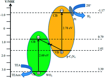 | ||
| Fig. 6 Schematic diagram of Z-scheme photocatalytic mechanism of WO3/g-C3N4 composite photocatalyst. | ||
In this study, the unsuitable contents of WO3 in WO3/g-C3N4 photocatalyst showed low photocatalytic activity for H2 production. Unfortunately, the reasons are not fully understood currently. We need the further studies to be clear the more detail photocatalytic mechanism of WO3/g-C3N4 composite.
Conclusions
In summary, the composite photocatalyst WO3/g-C3N4 was fabricated via a simple calcination method. The highest photocatalytic activity was achieved for 10 wt% WO3/g-C3N4 composite at H2 production rate of 110 μmol h−1 g−1, which was about 2 times higher compared to that of pure g-C3N4. Furthermore, the composite showed a good stability for the repeated H2 production reaction. The enhanced activity was due to the formation of WO3/g-C3N4 Z-scheme photocatalytic system and an efficient charge separation of the photo-generated electron–hole pairs. This present study would provide new insights on enhancing the photocatalytic H2 production activity of g-C3N4 by the formation of Z-scheme WO3/g-C3N4 composite photocatalyst.Acknowledgements
This work was partly supported by Grant-in-Aid for Scientific Research (C) no. 24510095 from the Ministry of Education, Culture, Sports, Science, and Technology of Japan.Notes and references
- X. C. Wang, K. Maeda, A. Thomas, K. Takanabe, G. Xin, J. M. Carlsson, K. Domen and M. Antonietti, Nat. Mater., 2009, 8, 76 CrossRef CAS PubMed; Q. J. Xiang, J. G. Yu and M. Jaroniec, J. Phys. Chem. C, 2011, 115, 7355 Search PubMed; J. G. Yu, S. H. Wang, B. Cheng, Z. Lin and F. Huang, Catal. Sci. Technol., 2013, 3, 1782 Search PubMed.
- Y. J. Cui, Z. X. Ding and X. Z. Fu, Angew. Chem., Int. Ed., 2012, 51, 11814 CrossRef CAS PubMed.
- G. H. Dong and L. Z. Zhang, J. Mater. Chem., 2012, 22, 1160 RSC; J. Mao, T. Peng, X. Zhang, K. Li, L. Ye and L. Zan, Catal. Sci. Technol., 2013, 3, 1253 Search PubMed.
- X. Wang, K. Maeda, X. Chen, K. Takanabe, K. Domen, Y. Hou, X. Fu and M. Antonietti, J. Am. Chem. Soc., 2009, 131, 1680 CrossRef CAS PubMed; Y. Wang, X. Wang and M. Antonietti, Angew. Chem., Int. Ed., 2012, 51, 68 CrossRef PubMed.
- S. C. Yan, Z. S. Li and Z. G. Zou, Langmuir, 2009, 25, 10397 CrossRef CAS PubMed.
- J. Zhang, M. Zhang, R. Q. Sun and X. Wang, Angew. Chem., Int. Ed., 2012, 51, 10145 CrossRef CAS PubMed.
- Y. J. Wang, R. Shi, J. Lin and Y. F. Zhu, Energy Environ. Sci., 2011, 4, 2922 Search PubMed; J. X. Sun, Y. P. Yuan, L. G. Qiu, X. Jiang, A. J. Xie, Y. H. Shen and J. F. Zhu, Dalton Trans., 2012, 41, 6756 RSC.
- X. Lu, Q. Wang and D. Cui, J. Mater. Sci. Technol., 2010, 26, 925 CAS.
- S. Kumar, T. Surendar, A. Baruah and V. Shanker, J. Mater. Chem. A, 2013, 1, 5333 CAS.
- H. Xu, J. Yan, Y. G. Xu, Y. H. Song, H. M. Li, J. X. Xia, C. J. Huang and H. L. Wan, Appl. Catal., B, 2013, 129, 182 CrossRef CAS PubMed; S. Yang, W. Zhou, C. Ge, X. Liu, Y. Fang and Z. Li, RSC Adv., 2013, 3, 5631 RSC.
- L. Ge, C. Han and J. Liu, Appl. Catal., B, 2011, 108/109, 100 CrossRef PubMed.
- W. C. Peng and X. Y. Li, Catal. Commun., 2014, 49, 63 CrossRef CAS PubMed.
- B. Chai, T. Peng, J. Mao, K. Li and L. Zan, Phys. Chem. Chem. Phys., 2012, 14, 16745 RSC; Y. D. Hou, A. B. Laursen, J. S. Zhang, G. G. Zhang, Y. S. Zhu, X. C. Wang, S. Dahl and I. Chorkendorff, Angew. Chem., Int. Ed., 2013, 52, 3621 CrossRef CAS PubMed; J. Chen, S. Shen, P. Guo, P. Wu and L. Guo, J. Mater. Chem. A, 2014, 2, 4605 Search PubMed.
- M. Miyauchi, M. Shibuya, Z. G. Zhao and Z. Liu, J. Phys. Chem. C, 2009, 113, 10642 CAS.
- M. Miyauchi, Phys. Chem. Chem. Phys., 2008, 10, 6258 RSC.
- T. Arai, M. Horiguchi, M. Yanagida, T. Gunji, H. Sugihara and K. Sayama, Chem. Commun., 2008, 5565 RSC; Q. Xiang, G. F. Meng, H. B. Zhao, Y. Zhang, H. Li, W. J. Ma and J. Q. Xu, J. Phys. Chem. C, 2010, 114, 2049 Search PubMed.
- D. Bi and Y. Xu, Langmuir, 2011, 27, 9359 CrossRef CAS PubMed; H. Widiyandari, A. Purwanto, R. Balgis, T. Ogi and K. Okuyama, Chem. Eng. J., 2012, 180, 323 CrossRef PubMed.
- H. Katsumata, Y. Oda, S. Kaneco and T. Suzuki, RSC Adv., 2013, 3, 5028 RSC.
- L. Huang, H. Xu, Y. Li, H. Li, X. Cheng, J. Xia, Y. Xu and G. Cai, Dalton Trans., 2013, 42, 8606 RSC; Y. Zang, L. Li, Y. Zuo, H. Lin, G. Li and X. Guan, RSC Adv., 2013, 3, 13646 RSC; K. Katsumata, R. Motoyoshi, N. Matsushita and K. Okada, J. Hazard. Mater., 2013, 260, 475 CrossRef CAS PubMed.
- Z. Jin, N. Murakami, T. Tsubota and T. Ohno, Appl. Catal., B, 2014, 150/151, 479 CrossRef PubMed; S. Chen, Y. Hu, S. Meng and X. Fu, Appl. Catal., B, 2014, 150/151, 564 CrossRef PubMed.
- Y. Zhang, J. Liu, G. Wu and W. Chen, Nanoscale, 2012, 4, 5300 RSC.
- S. C. Yan, S. B. Lv, Z. S. Li and Z. G. Zou, Dalton Trans., 2010, 39, 1488 RSC.
- K. Lee, W. S. Seo and J. T. Park, J. Am. Chem. Soc., 2003, 125, 3408 CrossRef CAS PubMed.
Footnote |
| † Electronic supplementary information (ESI) available: Experimental details and Fig. S1–S5. See DOI: 10.1039/c4ra02511c |
| This journal is © The Royal Society of Chemistry 2014 |

