Bo Ren,
Shiyang Bai,
Jihong Sun*,
Faqian Zhang and
Minghui Fan
Beijing University of Technology, Beijing, China. E-mail: jhsun@bjut.edu.cn; Fax: +86-10-67391983; Tel: +86-10-67396118
First published on 2nd May 2014
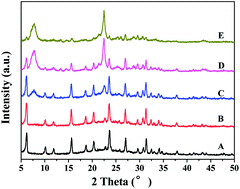
A stepwise-induced method with easy and simple preparations is proposed, which is used to successfully prepare the obvious core–shell structured Y/Beta composite zeolite using the pre-synthesized NaY-zeolite as a starting material. The composite zeolites with adjustable FAU/BEA features preliminarily present a good catalytic performance for cumene cracking, showing a strong potential application in petroleum processing.
In the past few decades, considerable efforts have been made to improve the gasoline quality and increase the yield of light oil in the oil refining and petrochemical industries. For this purpose, several studies have been conducted on the subject of mixing of different zeolites or adding some additives to zeolites as the FCC (fluid catalytic cracking) catalysts10–13 to achieve novel catalysts with extraordinary catalytic performance as compared to single zeolites. Although the mechanically mixed zeolites have little synergistic effect, they are hard to homogeneously mix at the micro- or nano-scale level. The principle aim of the present paper is to highlight the major successes of the synthesis of a novel composite zeolite with a hierarchical structure, such as MFI/MOR,14,15 MFI/BEA,16,17 FAU/LTA,18 FAU/EMT,19 FAU/BEA,20–22 and describe the benefits of their adjustable acidity, adsorption/separation and hydrophilic/hydrophobic properties. In this respect, various routes for the synthesis of micro/mesoporous composite materials have been initially explored,23–26 but the poor hydrothermal stability of mesoporous structures in composite materials has not yet been resolved, directly leading to considerable limitations on their extensive applications. Recently, the core–shell structured composite zeolites with two types of zeolites have been prepared, and the preliminary investigations presented enhancement in the synergistic effects and therefore reduction in the non-shape-selectivity occurrence was observed. Bouizi et al.17 proposed a pre-seeding (core)-deposited nanoseed (shell) method to synthesize the core–shell structured composite zeolites (BEA/MFI), which is very common and can be employed to synthesize various kinds of composite zeolites.14,18,19 However, the resultant particles of the prepared samples were too large to use in the field of catalysis; moreover, the synthesis pathways, including the modification of positive surface charge of the large core crystal (BEA-type) by using poly(diallyldimethylammonium) as a polycation agent and overgrowth of the negatively charged nanoseeds (MFI-type) via a hydrothermal treatment, were rather complicated. Li et al.21 prepared a novel Y/Beta composite zeolite using NaY zeolite powder as a core as well as the nutrients for Beta zeolite growth. As compared with Bouizi et al.'s proposed method,17 this synthesis procedure was obviously simple without surface treatment and seed absorbing on the core surface of crystal particles. Moreover, the obtained composite zeolite Y/Beta exhibited higher catalytic activity and selectivity than a physical mixture of Beta and Y zeolites. However, note that the features of core–shell structures was not obvious in the SEM and TEM images,20–22 although the XRD of this composite clearly revealed the presence of characteristic peaks of zeolites Beta and Y. Furthermore, Li et al.27 used TEA+-exchanged NaY zeolite powder as a core, and then added it into the pre-crystallized mixture to produce zeolite Beta, and the resulting structure of the as-synthesized samples presented more obvious core–shell zeolite composite; however, the NaY zeolite powder needed to be ion-exchanged twice in the solution (0.5 M TEA+), and it was also observed that the whole synthesis procedure was more complex than the surface treatment method.17–19 In this study, attention was given to the stepwise-induced synthesis strategy to prepare a Y/Beta composite zeolite with obvious core–shell structured characteristics in an extremely dense system. This procedure proved to be a convenient, facile and effective method without filtration of pre-synthesized zeolite Y and surface treatment of zeolite particles as compared to other reported methods.16–19,21
The sol–gel of core-Y zeolite, which contained the pre-synthesized NaY-zeolite, was firstly carried out, and then the aqueous solution of TEAOH (35%) was added. The third step involves the addition of silica (particle size was about 50 nm) and a certain amount of sulfuric acid to form a new gel having the molar composition: Na2O:
Al2O3
:
SiO2
:
TEAOH
:
H2O
:
H2SO4 = 4.7
:
1
:
15
:
3.9
:
260
:
4.7. Finally, the solid products were obtained via hydrothermal treatment. The detailed procedure of the synthesis is described in the ESI.†
![]() | ||
Fig. 1 XRD patterns of the Y/Beta composite zeolite with a crystallization time of (A) 0 h; (B) 68 h; (C) 70 h; (D) 74 h; and (E) 84 h. |
The size and morphology of the pre-synthesized zeolite Y particles, as well as the growth behaviors of the composite zeolite, were investigated using SEM (Fig. 2) and TEM (Fig. 3) observations. Fig. 2A shows the spherical crystals with a fine particle size of 0.8–1.0 μm, which can be attributed to the pure phase of zeolite Y particles, in good agreement with the XRD pattern shown in Fig. 1A. Fig. 2B shows that the surfaces of zeolite Y were wrapped with silica nanoparticles (around 50 nm as shown in the inset in Fig. 2B), which were added in the second-step, when the crystallization time was extended to 68 h. Moreover, as the crystallization time was further increased to 74 h, there were two phases observed, which can be seen in the micrograph of the composite zeolite Y/Beta, as shown in Fig. 2C. Specifically, the irregularly spherical phase with a much more coarse surface was attributed to the defective composite zeolite Y/Beta with particle size of around 1.5–2.0 μm. The magnified image shown in Fig. 2D presents a whole particle of composite zeolite Y/Beta with size of about 2.0 μm, whose surface was composed of many truncated octahedral nanoparticles with the size of around 500 nm, which was assigned to the typical morphology for zeolite Beta.1,9
![]() | ||
Fig. 2 SEM images of the pre-synthesized Y-zeolite (A) and Y/Beta composite zeolite with a crystallization time of (B) 68 h; (C) and (D) 74 h; and (E) 84 h. |
![]() | ||
Fig. 3 TEM images of Y/Beta composite zeolite with a crystallization time of (A) 70 h; (B); (C) 74 h (the insert is the magnified image), and (D) 74 h for EDX analysis. |
In addition, the presence of a small quantity of the monodispersed particles was noticed (Fig. 2C), and the basic reason for this was the constant growth by the stepwise-induced method, leading to the shedding of shell (zeolite Beta) from composite zeolite surface. When the crystallization time was prolonged to 84 h, the monodispersed particles of zeolite Beta with a diameter size of 0.5–1.0 μm were observed in Fig. 2E; however, the characteristic peaks of zeolite Y in the XRD patterns almost vanished. Therefore, the absence of zeolite Y evidently supported the stepwise-induced mechanism and is in good agreement with XRD patterns observed in Fig. 1E.
For more detailed information, the crystallization time was increased to 70 h, and the corresponding TEM image shows the phase of zeolite Beta on the particle surface of the zeolite Y (Fig. 3A), which is consistent with the observations of XRD pattern in Fig. 1C. The TEM images of Y/Beta composite zeolite (Fig. 3B) show the obvious core–shell structures, and the magnified image (Fig. 3C) in particular illustrates the well-ordered micropore channel array of the particle surface, indicating a highly crystallized microstructure. Furthermore, the chemical composition of a given zeolite is an important characteristic, which can define its type.28 Taking the sample with crystallization time of 74 h as an example, as can be seen in Fig. 3D, the selected particle presents a defective core–shell structure partly without the shell of Beta phase, which is very conducive for EDX analysis. EDX analysis indicates that the molar ratio of Si/Al of uncovered core and bare-shell was around 2.52 (Area a) and 8.54 (Area b), which were ascribed to Y phase and Beta phase, respectively. Particularly, Area c contained both zeolite Y and Beta, and its Si/Al ratio was about 6.07. Evidently, the EDX characterizations provide us a strong and direct evidence to prove the core–shell structure of Y/Beta composite zeolite. As compared with previous studies, the SEM and TEM images revealed that composite zeolite Y/Beta had prominent features of a core–shell structure, which is more obvious than that observed in the studies by Li et al.17–19
The thermogravimetric analysis and corresponding weight loss percentage as a function of temperature of all samples are listed in Table 1. In general, below 250 °C, the weight loss was mainly ascribed to the removal of adsorbed water (on the particles surface and in the micropores). In the present study, the zeolite Y was synthesized from inorganic aluminosilicate gel systems; therefore, there was a certain amount of adsorbed water (but no organic template) in the micropores. However, in the zeolite Beta, the micropores were filled with structure-directing agent (organic template) before calcination; therefore, its weight loss was attributed to the adsorbed water existing on the surface of particles. Thus, the weight loss of zeolite Y was obviously more than that of zeolite Beta during the periods when the temperature was below 250 °C. On the other hand, in the temperature span from 250 to 550 °C, the mass loss was mainly connected with the decomposition of the structure-directing agent existing in the micropores; thus, a higher weight loss was observed in zeolite Beta. Hence, according to the above discussion, the thermogravimetric analysis could be used to calculate the presence of approximate relative content of water in the composite zeolite. As summarized in Table 1, with the elongated crystallization time, the weight loss of all samples below 250 °C was reduced from 11.32% to 5.71%, but increased from 6.73% to 12.44% in a temperature range of 250–550 °C. These observations clearly indicated decrease in relative content of zeolite Y, but increase in the content of zeolite Beta with prolonged crystallization time, which is in good agreement with XRD patterns in Fig. 1.
Sample (crystallization time, h) | Signal (Temperature, °C) | ||
---|---|---|---|
<250 °C (wt%) | 250–550 °C (wt%) | >550 °C (wt%) | |
68 | 11.32 | 6.73 | 1.84 |
70 | 9.17 | 8.74 | 1.26 |
74 | 7.36 | 11.35 | 1.85 |
84 | 5.71 | 12.44 | 1.29 |
Evidently, the thermal stability of zeolite is an important parameter for their application in various fields.29 Taking the sample with crystallization time of 74 h as an example, both XRD pattern and DSC profile were employed to investigate its thermal stability of the core–shell structures. The observations that the intensity of the characteristic peaks calcined at 850 °C in XRD pattern was unchanged and no obvious phase transition exothermic peak appeared below 1000 °C in the DSC curve clearly indicate high thermal stability. The detailed illustrations are listed in the ESI.†
In addition, the cracking activities were preliminary evaluated with cumene as a probe molecule (ESI†). For instance, the catalytic performance of the composite zeolite at crystallization time of 74 h showed that the conversion of cumene reached as high as 86% at 300 °C for at least 400 min, showing that the composite zeolite had excellent catalytic properties for cracking reaction and anti-carbon deposition ability.
Footnote |
† Electronic supplementary information (ESI) available: Experimental procedures, the function relationship between areas of selected diffraction peaks for zeolite Y and its mass fraction in Y/Beta composite zeolite the cracking activities of cumene. See DOI: 10.1039/c4ra02494j |
This journal is © The Royal Society of Chemistry 2014 |