Shaozheng Hu*a,
Lin Mab,
Jiguang Youc,
Fayun Lia,
Zhiping Fana,
Fei Wangc,
Dan Liud and
Jianzhou Gui*d
aInstitute of Eco-environmental Sciences, Liaoning Shihua University, Fushun 113001, PR China. E-mail: hushaozhenglnpu@163.com; Tel: +86-24-56860865
bSchool of Petrochemical Engineering, Liaoning Shihua University, Fushun 113001, P.R. China
cSchool of Environmental and Biological Engineering, Liaoning Shihua University, Fushun 113001, PR China
dCollege of Chemistry and Materials Science, Liaoning Shihua University, Fushun 113001, PR China. E-mail: jzguilnpu@163.com; Tel: +86-24-56860865
First published on 7th May 2014
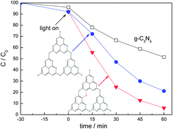
Phosphorus doped g-C3N4 was prepared by a simple method using dicyandiamide monomer and diammonium hydrogen phosphate as precursors. X-ray diffraction (XRD), UV-Vis spectroscopy, Fourier transform infrared spectra (FT-IR), photoluminescence (PL), X-ray photoelectron spectroscopy (XPS) and photocurrent measurement were used to characterize the prepared catalysts. The results indicated that the introduction of phosphorus inhibited the crystal growth of graphitic carbon nitride, decreased the band gap energy and increased the separation efficiency of photogenerated electrons and holes. The P doping site is influenced by the phosphorus source. Interstitial P doping is more effective in improving the photocatalytic activity of Rhodamine B (RhB) degradation compared with substitutional P doping. A possible mechanism was proposed.
Recently, graphitic carbon nitride (g-C3N4) has attracted a great deal of interest in photocatalytic applications. Carbon nitride can exist in five phases, α, β, cubic, graphitic and pseudocubic, among which graphitic phase is regarded as the most stable structure. The heptazine ring structure and high condensation degree make it possess many advantages, such as good chemical stability, appropriate band gap energy and unique electronic structure. In addition, g-C3N4 is metal-free and easily-synthesized via one-step polymerization of cheap raw materials. All of these make g-C3N4 to be the best candidate for photocatalytic application. However, g-C3N4 also suffers from many disadvantages, such as the low carrier mobility, low visible-light utilization efficiency, high recombination rate and small BET surface area. Therefore, modification of g-C3N4 with other metal or non-metal element was developed in recent years.12–18
It is known that g-C3N4 contains nitrogen triangles having six lone-pair electrons, which are available for nonmetal doping. Therefore, nonmetal doping of g-C3N4 seems to be a feasible way to deal with those drawbacks. Yan et al. prepared boron-doped g-C3N4 by heating the mixture of melamine and boron oxide.12 They suggested that boron doping increased the photocatalytic activity of RhB degradation due to the improvement of dye adsorption and light absorption of catalyst. Zhang et al. used elemental sulfur (S8) as the solvent and mediator to promote the photocatalytic performance of prepared g-C3N4.13 This sulfur-flux-mediated polymerization route of carbon nitride improved its intrinsic texture, morphology, optical and electronic properties, thus increased the photocatalytic water reduction performance. Generally speaking, conjugated polymer doped with higher periodic elements tends to show narrower band gap. For example, polythiophene shows a decreased band gap than that of polypyrrole.19 Therefore, phosphorus atom is expected to be the ideal dopant to tune the texture and electronic structure of g-C3N4. Zhang et al. first synthesized phosphorus doped g-C3N4 using dicyandiamide and ionic liquid [Bmim]PF6 as raw material.14 They found the electrical conductivity and photocurrent were significantly improved after phosphorus doping. After that, Zhang et al. synthesized the phosphorus doped g-C3N4 using the same raw material.15 The obtained phosphorus doped g-C3N4 exhibited obvious improved photocatalytic activities for RhB and methyl orange degradation under visible light. However, ionic liquid [Bmim]PF6 is not an optimal phosphorus source because of its high price and complicated synthesis process. It is known that the doping site can significantly influence the properties of prepared catalysts. There are many literatures concerning the effect of N doping site on properties and photocatalytic performance of prepared TiO2 based catalysts. N dopant can enter the TiO2 matrix by either direct substitution of an oxygen site or by stationing itself interstitially. The difference in doping site could cause the different oxygen vacancy content and band gap structure, thus leading to the difference in activity. Although many metal and non-metal element doped g-C3N4 catalysts were reported, few of those literatures investigated the effect of doping site on the photocatalytic activity of prepared g-C3N4 based catalysts. Hence, in this work, a simple method to synthesize phosphorus doped g-C3N4 using diammonium hydrogen phosphate as phosphorus source is reported. The photocatalytic activities were evaluated in the photocatalytic degradation of RhB under visible light. For comparison, [Bmim]PF6 was also used as the phosphorus source to investigate the effect of P doping site on the structural property, optical property and photocatalytic performance of prepared g-C3N4 based catalysts. The possible reaction mechanism is proposed.
XRD patterns of the prepared TiO2 samples were recorded on a Rigaku D/max-2400 instrument using Cu-Kα radiation (λ = 1.54 Å). UV-Vis spectroscopy measurement was carried out on a JASCO V-550 model UV-Vis spectrophotometer, using BaSO4 as the reflectance sample. Fourier transform infrared spectra (FT-IR) were obtained on a Nicolet 20DXB FT-IR spectrometer. Elemental analysis was performed with a vario EL cube from Elementar Analysensysteme GmbH. XPS measurements were conducted on a Thermo Escalab 250 XPS system with Al Kα radiation as the exciting source. The binding energies were calibrated by referencing the C 1s peak (284.6 eV) to reduce the sample charge effect. Photoluminescence (PL) spectra were measured at room temperature with a fluorospectrophotometer (FP-6300) using a Xe lamp as excitation source. Working electrodes were prepared as follows: 0.3 g of sample was ground with 0.7 g of ethanol to make a slurry, then coated on an indium–tin oxide glass by the doctor blade method. Photocurrents were measured by electrochemical analyzer (CHI 618C Instruments) in a standard three electrode system which the prepared sample film was used as the working electrodes, a Pt flake as the counter electrode, and Ag/AgCl as the reference electrode. A 500 W Xe-lamp was used to irradiate the working electrode from the back side. A 1.0 M Na2SO4 solution was used as the electrolyte.
To characterize the specific surface area of g-C3N4 based catalysts, the nitrogen adsorption and desorption isotherms were measured (Fig. 2). The isotherm of both g-C3N4 and P(6%)-CN are of classical type IV, suggesting the presence of mesopores. The hysteresis loop in the low pressure range (0.4 < P/P0 < 0.8) is associated with the intra-aggregated pores. The high-pressure hysteresis loop (0.8 < P/P0 < 1) is related to the larger pores formed by the accumulation of secondary particles. The BET specific surface areas (SBET) of g-C3N4, P(2%)-CN, P(4%)-CN, P(6%)-CN, P(8%)-CN, P(10%)-CN and IL-P(6%)-CN are calculated to be 10.9, 12.4, 14.8, 16.5, 17.7, 18.6 and 16.9 m2 g−1. P(6%)-CN and IL-P(6%)-CN exhibit the comparable BET specific surface area. The SBET increases with increasing the P content. This increased SBET could be probably due to that P doping inhibited the crystal growth of graphitic carbon nitride, leading to the formation of more secondary particles. The large SBET can promote adsorption, desorption and diffusion of reactants and products, which is favorable to the photocatalytic performance.
FT-IR spectra shown in Fig. 3 can provide plentiful structural information concerning of synthesized g-C3N4, P(6%)-CN and IL-P(6%)-CN. For g-C3N4, a series of peaks in the range from 1200 to 1600 cm−1 are attributed to the typical stretching modes of CN heterocycles, while the sharp peak located at 810 cm−1 is assigned to the bending vibration of heptazine rings, which indicating the synthesized g-C3N4 is composed of heptazine units. The broad absorption band around 3200 cm−1 is originated from the stretching vibration of N–H bond, associated with uncondensed aminogroups.12 For P(6%)-CN and IL-P(6%)-CN, all the characteristic vibrational peaks of g-C3N4 are observed, suggesting that the structure of g-C3N4 is not changed after phosphorus doping. Zhang et al.15 synthesized P doped g-C3N4 using [Bmim]PF6 as phosphorus source. The vibrations of P-related group were not observed in their investigation. They attributed it to the low phosphorus content or its vibration was overlapped by that of C–N bond. In this investigation, no P-related group was observed in IL-P(6%)-CN, which is consistent with the previous results.14,15 However, a peak centered at ca. 950 cm−1 is clearly observed in the spectra of P(6%)-CN, which is assigned to the P–N stretching mode. This is probably due to that the different phosphorus source causes the different P doping site.
The light absorption property of as-prepared g-C3N4, P(x%)-CN and IL-P(6%)-CN catalysts is studied by UV-Vis spectra, and the results are shown in Fig. 4. Pure g-C3N4 shows a typical semiconductor absorption, originating from charge transfer response of g-C3N4 from the VB populated by N 2p orbitals to the CB formed by C 2p orbitals.20 For P(x%)-CN, the obvious red shifts of absorption band were observed with increasing the phosphorus content, indicating phosphorus doping changed the optical property of synthesized g-C3N4, thus decreased the band gap energy. The band gap energy, which is calculated according to the method of Oregan and Gratzel, is 2.7 eV for g-C3N4. This is consistent with the previous results.23–25 In the case of IL-P(6%)-CN, P(2%)-CN, P(4%)-CN, P(6%)-CN and P(10%)-CN, this value decreased to 2.68, 2.66, 2.65, 2.63 and 2.60 eV. This result is consistent with the academic calculation result of electronic structure of phosphorus doped g-C3N4 using first-principles reported by Ma et al.26 They found a isolated P 3p state is localized just 0.15 eV below the bottom of the CB of the host g-C3N4, leading to the decreased band gap energy. For IL-P(6%)-CN, the absorption band was only slight changed compared with g-C3N4. This obvious difference in optical property between IL-P(6%)-CN and P(6%)-CN was probably due to the difference in P doping site. The possible reason is discussed (see below).
XPS were conducted to confirm the structure of g-C3N4 and the chemical state of phosphorus. In Fig. 5a and b, the spectra of g-C3N4 in both N 1s and C 1s region can be fitted with three contributions. For N 1s region (Fig. 5a), three contributions located at 398.2, 399.2 and 400.3 eV were assigned to the sp2 hybridized aromatic nitrogen atoms bonded to carbon atoms (C–N
C), tertiary nitrogen N–(C)3 groups linking structural motif or amino groups carrying hydrogen ((C)2–N–H) inconnection with structural defects and incomplete condensation, and nitrogen atoms bonded three carbon atoms in the aromatic cycles.27,28 In Fig. 5b, three components located at 284.6, 285.8 and 287.6 eV for g-C3N4 were attributed to the C–C bond which originated from sp2 C atoms bonded to N in an aromatic ring (N–C
N), C
N or C
N which could be ascribed to defect-containing sp2 hybridized carbon atoms present in graphitic domains and pure graphitic sites in a CN matrix.29–31 It is shown in Fig. 5 that the spectra of P(6%)-CN and IL-P(6%)-CN in N 1s and C 1s regions also can be fitted with three contributions. However, the obvious shifts to higher binding energies were observed for P(6%)-CN and IL-P(6%)-CN in N 1s and C 1s regions compared with that of g-C3N4. This is probably due to the change of chemical environment after phosphorus doping. However, no obvious difference in binding energies between P(6%)-CN and IL-P(6%)-CN in N 1s and C 1s regions was observed, indicating the difference in P doping site did not influence the chemical environment of C and N atoms in g-C3N4.
![]() | ||
| Fig. 5 XP spectra of synthesized g-C3N4, P(6%)-CN and IL-P(6%)-CN in the region of N 1s (a), C 1s (b) and P 2p (c). | ||
Fig. 5c showed that the binding energies of P(6%)-CN and IL-P(6%)-CN in P 2p region were located at 133.4 and 133.7 eV. It is reported that the binding energy of P 2p in P–N and P–C bonds was 133.5 eV and 131.5–132.5 eV, respectively.14 Thus, it is deduced that phosphorus doped into g-C3N4 lattice in the formation of P–N bond. This binding energy difference, 0.3 eV, was probably due to the different chemical environment of P atoms in two catalysts. Zhang et al. suggested that the phosphorus heteroatoms most probably replace the corner or bay carbon to form P–N bond in the doped C3N4 framework, as shown in Fig. 6a.14 Ma et al. calculated the dopant formation energies and electronic properties of S and P doped g-C3N4 systems using first-principles density functional theory.26 They suggested that S atom preferentially substitutes for the edge N atom of g-C3N4, whereas the P atom preferentially situates the interstitial sites of in-planar of g-C3N4, as shown in Fig. 6b. Obviously, in Fig. 6, P atoms bond to three N atoms when it replaces the carbon atoms. Whereas, only two P–N bonds formed when the interstitial doping occurs. Because the electronegativity of N atom is higher than that of P atom, more P–N bonds causes the lower electron density of P atoms, leading to the higher binding energy of IL-P(6%)-CN. Therefore, summarizes the obtained results above, it is deduced that P doping site is influenced by the phosphorus source. Substitutional doping occurs using [Bmim]PF6 as phosphorus source, whereas interstitial doping occurs when (NH4)2HPO4 is used. In addition, elemental analyse results revealed that the C/N ratio for g-C3N4 is 0.72, obviously higher than that of IL-P(6%)-CN (0.69). This is probably due to that partial C atoms were replaced by P atoms. However, for P(6%)-CN, this value is 0.71, similar to that of g-C3N4. This result confirms our point of view. Besides, the P concentrations in prepared catalysts were also measured by elemental analyse. The results indicated that the molar ratio of P element to g-C3N4 were 0.03, 0.056, 0.08, 0.11, 0.14 and 0.082 for P(2%)-CN, P(4%)-CN, P(6%)-CN, P(8%)-CN, P(10%)-CN and IL-P(6%)-CN. These values were very close to the theoretical value, indicating that P element did not lose during the preparation process.
Fig. 7 shows the room temperature PL spectra of g-C3N4, P(x%)-CN and IL-P(6%)-CN under the excitation wavelength of 320 nm. For g-C3N4, the broad PL band is around 465 nm, which can be attributed to the band–band PL phenomenon with the energy of light approximately equal to the band gap of g-C3N4 calculated by UV-Vis spectra.30 Such band–band PL signal is attributed to excitonic PL, which mainly results from the n–π* electronic transitions involving lone pairs of nitrogen atoms in g-C3N4.32 In the case of P doped g-C3N4, the shape of the curves is similar to that of g-C3N4, whereas the peak intensities significantly decrease. Considering that the PL emission results from the free charge carrier recombination, the decreased peak intensity indicates that P doped g-C3N4 exhibits lower electrons–holes recombination rate compared with g-C3N4. The previous calculation results show that phosphorus doping can increase the dispersion of the contour distribution of HOMO and LUMO, which improves the carrier mobility.26 The noncoplanar HOMO and LUMO favors the separation of photogenerated e−/h+ pairs and thus decreases the recombination rate. Obviously, the PL intensity of IL-P(6%)-CN is higher than that of P(6%)-CN. This indicated that P doping site could influence the separation rate of photogenerated e−/h+ pairs. Besides, the PL intensity of P(8%)-CN is stronger than that of P(6%)-CN, indicating the excess doping phosphorus could act as recombination centers for excited electrons and holes.
The generation of electrons–holes pairs as well as their separation, migration and capture by the reactive species is regarded as the basic process for the photocatalysis. Photoelectrochemistry test is a powerful tool to monitor these complicated processes. Fig. 8 shows the photocurrent responses of g-C3N4, P(6%)-CN and IL-P(6%)-CN. Obviously, the sharp increased photocurrent responses appeared for three catalysts once the pulse Xe lamp was applied. Besides, the photocurrent responses did not decay with increasing the illuminated time, indicating the prepared catalysts could provide stable quantity of electrons and holes during the irradiation. The photocurrent value of P(6%)-CN was much higher than that of g-C3N4 and IL-P(6%)-CN, which can be attributed to the more efficient separation of photogenerated electron–hole pairs.
Fig. 9a shows the photocatalytic performances of g-C3N4, P(x%)-CN and IL-P(6%)-CN in the degradation of RhB under visible light irradiation. Before the light on, the RhB concentrations of P doped g-C3N4 were slightly lower than that of g-C3N4. This is probably due to that phosphorus doping changed the surface property of synthesized carbon nitride, leading to the improved RhB adsorption ability. Control experiments (not shown here) indicated that the RhB degradation rate can be ignored in the absence of either irradiation or photocatalyst, indicating that RhB was degraded via photocatalytic process. P(x%)-CN showed obviously higher activities than g-C3N4. The degradation rate increased with increasing x% to the maximum of 6%, beyond which the activity of the catalysts began to decrease. This trend is exactly opposite to the PL intensity order. Among the synthesized phosphorus doped g-C3N4 catalysts, no essential difference in optical property is shown in UV-Vis spectra, therefore the photocatalytic performance of P(x%)-CN is mainly determined by electrons–holes separation efficiency. When the P content was beyond the optimal value, the recombination of photogenerated electrons and holes increased, leading to the decreased activities of P(8%)-CN and P(10%)-CN. Besides, P(6%)-CN exhibited much higher activity than that of IL-P(6%)-CN. Considering that, the P concentration of P(6%)-CN and IL-P(6%)-CN which measured by elemental analyse is very close (molar ratio P/g-C3N4 = 0.08 and 0.082), the difference in photocatalytic performance between them should be not caused by the P concentration but by the different doping site. Interstitial P doping is more effective to improve the photocatalytic activity compared with substitutional P doping.
![]() | ||
| Fig. 9 Photocatalytic performances of g-C3N4, P(x%)-CN and IL-P(6%)-CN (a) and plot of −ln(C/C0) against reaction time (b) in the degradation of RhB under visible light irradiation. | ||
The reaction rate constant k was obtained by assuming that the reaction followed first order kinetics.33 In a batch reactor, the performance equation is as follows: −ln(C/C0) = kt where C0 and C represent the concentrations of RhB dye before and after photocatalytic degradation, respectively. If a linear relationship is established when −ln(C/C0) is plotted against t (reaction time), the rate constant k can be obtained from the slope of the line. Fig. 9b displays the plot of −ln(C/C0) against reaction time. The calculated results indicated that the rate constant k was 0.0115, 0.0169, 0.0243, 0.0466, 0.0277, 0.0222 and 0.0258 min−1 for g-C3N4, P(2%)-CN, P(4%)-CN, P(6%)-CN, P(8%)-CN, P(10%)-CN and IL-P(6%)-CN respectively. P(6%)-CN exhibited the highest rate constant which is 4 and 1.8 times higher than that of g-C3N4 and IL-P(6%)-CN. This increased photocatalytic performance should be attributed to the synergistic effect of decreased band gap energy which utilize visible light more efficiently, improved electrons–holes separation efficiency and increased RhB adsorption ability which caused by phosphorus doping.
To check the catalytic stability of P doped g-C3N4, the photocatalytic performance of P(6%)-CN was investigated in three circles (Fig. 10a). No obvious decrease in activity was observed after three circles, indicating that prepared P doped g-C3N4 is stable under visible-light irradiation. Moreover, the P element concentrations of fresh and reused P(6%)-CN which measured by elemental analyse were 0.08 and 0.081. No essential difference was observed between them, indicating the structure of P(6%)-CN is stable. Fig. 10b shows the comparison of XP spectra of fresh and reused P(6%)-CN in the region of P 2p. The binding energy is not changed after three circles, indicating that the chemical state of P element is stable.
![]() | ||
| Fig. 10 The catalytic stability test of P(6%)-CN (a) and comparison of XP spectra of fresh and reused P(6%)-CN in the region of P 2p (b). | ||
In order to clarify the mechanism on the improved activity of phosphorus doped g-C3N4 in depth, the active species generated during the reaction process are identified by hole and free radical trapping experiment. In this investigation, EDTA-2Na, tert-butyl alcohol (t-BuOH) and 1,4-benzoquinone (BQ) are used as the hole (h+) scavenger, hydroxyl radical (˙OH) scavenger and superoxide radical (˙O2−) scavenger, respectively.34 Fig. 11 shows the influence of various scavengers on the visible light photocatalytic activity of g-C3N4, P(6%)-CN and IL-P(6%)-CN. For g-C3N4, the photodegradation rate of RhB decreased slightly after the addition of t-BuOH, indicating that hydroxyl radicals are not the main active species in current photocatalytic systems. When BQ was added, the degradation of RhB was inhibited sharply, indicating ˙O2− is the main active species in current photocatalytic systems. It is reported that the CB and VB of g-C3N4 were −1.12 V and +1.57 V, respectively.21 Whereas, the redox potentials for ˙OH/OH− and O2/˙O2− were determined to be +1.99 V and −0.33 V.35 Therefore, the reduction potential of CB electrons in g-C3N4 was negative enough to reduce O2 to form ˙O2−, whereas the VB holes in g-C3N4 were not positive enough to generate ˙OH. This is consistent with our experiment results. In the presence of EDTA-2Na, the RhB degradation rate is increased obviously, which is different from previous result.34 Zhang et al. prepared C3N4/Bi5Nb3O15 heterojunction catalyst for 4-CP photodegradation.34 The photodegradation rate was decelerated significantly after the addition of EDTA-2Na, indicating the direct photogenerated holes oxidation happened. In our investigation, although the redox potential of RhB is reported to be 1.43 V,36 which is higher than the VB of g-C3N4, the direct photogenerated holes oxidation did not happen. On the contrary, the addition of EDTA-2Na to trap the h+ can promote the separation rate of e−/h+ pairs, leading to the increased photocatalytic performance. For P(6%)-CN and IL-P(6%)-CN, the similar trend was obtained, indicating the main oxidative species is the same as that of g-C3N4. The difference in phosphorus doping site does not change the reaction mechanism.
![]() | ||
| Fig. 11 Influence of various scavengers on the visible light photocatalytic activity of g-C3N4, P(6%)-CN and IL-P(6%)-CN. | ||
| This journal is © The Royal Society of Chemistry 2014 |