High-temperature steam reforming of bio-oil derived light organics and methane to hydrogen-rich gas with trace CO via rational temperature control

Xun Huac, Lijun Zhangb, Dehua Dongc and Gongxuan Lu*a
aNational Engineering Research Centre for Fine Petrochemical Intermediates, State Key Laboratory for Oxo Synthesis and Selective Oxidation, Lanzhou Institute of Chemical Physics, Chinese Academy of Sciences, Lanzhou 730000, P. R. China. E-mail: gxlu@lzb.ac.cn; Tel: +86 931 4968178
bDepartment of Chemistry, Lanzhou University, Tianshui Road 222, Lanzhou 730000, P. R. China
cFuels and Energy Technology Institute, Curtin University of Technology, Perth, WA 6845, Australia

Received 9th March 2014 , Accepted 10th April 2014

First published on 11th April 2014


Abstract

Steam reforming of methane or bio-oil is generally performed at high temperatures (>600 °C) to maintain the efficiency of the process. One main disadvantage of steam reforming at that high temperature is the formation of a large amount of CO due to the predomination of the reverse water gas shift reaction and the reformate gas with this level of CO cannot feed fuel cells. In this study a reactor with constant and decreasing temperature zones is developed to produce hydrogen-rich gas with trace CO from bio-oil derived light organics and methane. In the constant-temperature zone, the high temperature employed effectively promotes the reforming of organics and suppresses the generation of both complex organic by-products and coke. In the decreasing temperature zone, the CO produced in the constant-temperature zone is stepwisely and efficiently reduced to a ppm level using steam. In addition, the coke distribution along the catalyst bed varied a lot in the constant-temperature zone and the decreasing temperature zone, due to the different reaction network in the different temperature ranges. Via rational reaction temperature control, the efficient reforming of methane and the bio-oil derived light organics and the simultaneous elimination of CO is successfully achieved in one step in one reactor.

Introduction

Fuel cells have great potential to power the next generation of vehicles due to their high efficiency and easy portability.1–5 Hydrogen can be used as the fuel for some high performance fuel cells such as the proton-exchanged membrane fuel cell (PEMFC). However, the use of hydrogen fuel creates problems such as safety issues due to its inflammable nature and the lack of infrastructure for its storage. On-board hydrogen production from liquid fuels is a potential solution to solve the safety and storage problems associated with the use of hydrogen as a fuel.6–10 Among the various fuels available, bio-oil, in particular, is a very promising hydrogen source.11,12 Bio-oil can be produced via fast pyrolysis of the renewable, wide spread and abundantly available biomass with the yields up to 70 wt%. The use of bio-oil as hydrogen resource almost does not create net CO2 emission as the CO2 released during steam reforming of bio-oil is took up by the growth of biomass.

Nevertheless, bio-oil is very complex and steam reforming of bio-oil at low temperatures is difficult, due to the low conversion of heavy components in bio-oil and the production of a significant amount of organic by-products and unacceptable level of coke.12 Steam reforming of bio-oil at high temperatures can prevent the formation of organic by-products effectively and suppress coke formation to some extent. The disadvantages of bio-oil steam reforming in the high temperature range is the formation of large amount of CO due to the predomination of reverse water gas shift reaction at this condition [eqn (1)].13 CO is not desirable in the reformate gas as it can poison the anode catalyst and significantly lower efficiency of fuel cells.

How to suppress CO formation in bio-oil reforming at the temperature above 600 °C is the bottleneck problem for the application of bio-oil as the source of hydrogen. CO comes from both decomposition of organics and the reverse water gas shift reaction, reaction equilibriums of which are controlled by reaction temperature. Hence, via rational reaction temperature control, the efficient reforming of bio-oil and the simultaneous elimination of CO may be achieved in one step or in one reactor.

To accomplish this concept, a reactor with constant and decreasing temperature zone is developed in this paper. Steam reforming of bio-oil occurs in the constant high temperature zone, efficiently producing the gas mixtures containing mainly H2, CO, and CO2. The stepwise and efficient removal of CO by water gas shift reaction [eqn (2)] is achieved in a decreasing temperature zone. The total reactor system can efficiently convert bio-oil to gas mixtures at high temperatures and simultaneously reduce CO concentration to a ppm level in one step. This reactor has the potential application in the vehicles with fuel cell system, since it does not require extensive space and can efficiently generate the hydrogen-rich gas with trace CO from bio-oil or methane steam reforming in a very wide temperature region.

 
H2 + CO2 → H2O + CO (ΔH0298 = 41.1 kJ mol−1) (1)
 
CO + H2O → H2 + CO2H0298 = −41.1 kJ mol−1) (2)

Experimental section

Catalytic reactor

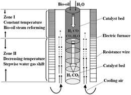
Configuration of the reactor system is present in Fig. 1. An electric furnace (i.d. 35 mm) and a quartz reactor loaded with catalyst (i.d. 8 mm) compose the steam reformer. The output power of the furnace is different in different position. In upper part of the furnace (Zone I), distribution of the resistance wire is uniform and dense, while the resistance wire is very sparse in lower part of the reactor (Zone II), especially at end of the furnace. In addition, there are gaps existed between the quartz reactor and inner wall of the furnace. If the gap on top of the reactor is sealed with insulation material while the gap in the end keeps open, then the cooling air will be introduced to the reactor due to the cross-ventilation. The decreasing power output plus the cooling air will result in formation of a region with decreasing temperatures. In converse, the temperature in Zone I is constant and not affected much by the airflow, since the cooling air is gradually heated up by the furnace.
image file: c4ra02037e-f1.tif
Fig. 1 Scheme of the reactor with cooling device.

Four typical reforming temperatures (500, 600, 700, 800 °C) are set in the reactor with rational temperature distribution, and the actual temperatures measured by a thermocouple along with the furnace (top to end, length: 50 cm) are depicted in Fig. 2. The temperature distribution can be approximately categorized into two zones: Zone I is from top to 22 cm of the reactor, where the temperatures approximately equals to the setting temperatures. Zone II locates in the range of 22–50 cm, where the temperatures decrease almost continuously. At outlet of the reactor, the temperatures are decreased in the region of 140–300 °C.


image file: c4ra02037e-f2.tif
Fig. 2 Actual temperature distribution in the reactor with rational temperature distribution.

Theoretically, the CO produced in Zone I can be stepwisely converted to H2 and CO2 with steam in Zone II. This is because the temperatures in Zone II decreases gradually to the mild range, which is highly favorable for occurrence of water gas shift reaction to remove CO. High-temperature reforming of bio-oil and methane is performed in this reactor to investigate its feasibility for elimination of high concentration of CO in hydrogen-rich gas.

Experimental procedures

Catalytic tests are performed at atmospheric pressure in a traditional reactor and the reactor with cooling device that has been shown in Fig. 1. A mixed solution of acetic acid, ethanol, and acetaldehyde (molar ratio: 1[thin space (1/6-em)]:[thin space (1/6-em)]1[thin space (1/6-em)]:[thin space (1/6-em)]1) is prepared to simulate the light components in bio-oil. It needs to be noted that the simulated bio-oil is very different to the real bio-oil. The real bio-oil contains hundreds of both light and heavy organics, which includes the sugar derived light components (i.e. carboxylic acids, aldehydes, ketones and alcohols), sugars (i.e. glucose, levoglucosan, xylose), and phenolics (i.e. phenol and other big aromatics).14–17

Typically, the simulated bio-oil is fed into a pre-heater by a syringe pump with a flow rate of 0.16 ml min−1 and a steam to carbon ratio (S/C) of 7. The vaporized reaction mixture is then fed into the reactor using N2 (40 ml min−1) as a carrier gas. Separation and quantification of the products are attained by two on-line chromatographs equipped with thermal-conductivity detector (TCD) and flame ionization detector (FID). A CO sensor (sensitivity: 50 ppm) is also employed to detect the low concentration of CO. Conversion of the light organics is calculated by dividing the amount the three organic compounds consumed with the total amount in feed. Composition of the gaseous product (dry basis) is calculated by their molar ratios in the reformate gas. Their yields are calculated by dividing the amount produced with the theoretical amount produced. Conversion and product composition in methane steam reforming are defined in a similar way.

Catalyst preparation

The configuration of the reactor makes it necessary to have a long catalyst bed. Thus, an impregnation–reduction method is employed to prepare Ni/Al2O3 catalyst in situ. Briefly, the reactor (from top to end) is filled up with the support γ-Al2O3 beforehand, and a saturated solution of Ni(NO3)2 is introduced into the reactor to impregnate the alumina support by a syringe pump with a flow rate of 0.26 ml min−1 for 60 min. After that, the impregnated catalyst was heated to 600 °C for 3 h in hydrogen atmosphere, during which the nickel nitrate decomposed to nickel oxide or simultaneously was reduced to metallic nickel species. Nickel loading is 16 wt% to Al2O3, which was determined by atomic absorption after digestion of the catalysts with sulfuric acid. Ni–K/Al2O3 catalyst was prepared via the similar way and the loading of potassium is 5 wt%. Via this impregnation–reduction method the catalyst can be prepared in situ, which is very simple and saves a lot of time when compared with the conventional impregnation method that includes a number of steps such as impregnation, drying, calcinations, and reduction. The amount of coke on catalyst is analyzed by thermo-gravimetric analysis in a PerkinElmer TG/DTA apparatus. The catalyst is heated at 10 °C min−1 under synthetic air flow and the mass loss is recorded (experimental error: ±0.5%).

Results and discussion

Steam reforming of the light organics in the reactor with rational temperature distribution

Steam reforming of the light organics is performed over the catalyst prepared by impregnation–reduction method in the traditional reactor (TR) with constant temperature and the reactor with rational temperature distribution (RRTD), respectively. Conversions of the reactants and gas compositions versus reaction temperature are depicted in Fig. 3. In the high temperature region (>600 °C), the reactant is effectively reformed to gaseous products and the production of complex organic by-products is suppressed, indicating that the high-temperature reforming is necessary for effective gasification of the organics. Although reactant conversions in TR and RRTD are comparable, the product distributions are practically distinct. Gas compositions in TR are mainly controlled by thermodynamic equilibrium. Production of CH4 decreases remarkably at high reaction temperatures. In converse, CO amount increases drastically versus the increasing temperatures, leading to low H2 and CO2 yields. The high temperatures employed highly favor occurrence of the reverse water gas shift reaction to produce CO.18
image file: c4ra02037e-f3.tif
Fig. 3 Conversion of the light organics derived from bio-oil and product distributions in steam reforming: S/C = 7, bio-oil solution flow rate = 0.16 ml min−1, P = 1 atm; (a) in TR; (b) in RRTD; the concentration of CO can be further decreased to 119 ppm at S/C of 10 and 600 °C. (c) effects of the addition of K to Ni/Al2O3 catalyst on product distribution in RRTD. Xbio-oil in figures stands for the overall conversion of acetic acid, acetaldehyde and ethanol.

In RRTD, the results are very different. CO amounts decrease to trace level in the whole temperature region investigated. For example, the CO concentration decreases from 8.2% in TR to 412 ppm in RRTD at 600 °C, while it decreases from 38.9% to 1936 ppm at 800 °C. The stepwise decreasing temperature effectively catalyzes the water gas shift reaction to remove CO, due to the high equilibrium constant of this reaction at the mild temperatures. Nevertheless, although the production of CO is substantially suppressed, the production of CH4 is remarkably promoted, which similarly leads to low H2 yield.

In general, CH4 can be efficiently steam reformed at high temperatures, while its amount always reaches a high level at the mild temperatures due to the domination of methanation reaction at this stage.19 The mild temperature region in Zone II of RRTD should be responsible for generation of the large amount of CH4. In our previous study,20 we found that modification of reforming catalyst with potassium can effectively inhibit the production of CH4, we therefore introduce KNO3 solution on catalyst surface using a syringe pump. Concentration of KNO3 solution is regulated to achieve a K loading of 5 wt%. The catalytic results over Ni–K/Al2O3 catalyst are presented in Fig. 3c. The production of CH4 is substantially reduced at either 500 or 800 °C. Only H2 and CO2 are produced as the main products in the whole temperature region. Furthermore, the addition of K also remarkably promotes the catalytic activity. Nevertheless, the introducing K on catalyst surface does not show remarkable inhibition effect on the production of CO, but CO can be further decreased via increasing ratio of steam to reactants. For example, the concentration of CO can be decreased to 119 ppm at S/C of 10 and 600 °C. The hydrogen-rich gas with this level of CO may be even directly fed the fuel cells with higher tolerance of CO.21 The low concentration of CO in reformate gas is related to the high efficiency of the RRTD for CO elimination.

Catalytic activity of the TR and RRTD for water gas shift reaction

To verify the efficiency of RRTD for water gas shift reaction, the catalytic activities of Ni–K/Al2O3 catalyst in TR and RRTD for water gas shift reaction are further investigated. CO conversions and product compositions as functions of reaction temperature are present in Fig. 4. In TR, the catalyst is highly active at the initial temperature of 500 °C, CO is completely converted, and CH4 is produced as the only by-product. However, CO conversion decreases significantly versus the increasing reaction temperature, which is caused by limitation of the thermodynamic equilibrium of water gas shift reaction. In converse, the catalytic activity of Ni–K/Al2O3 catalyst in RRTD is almost independent of the reaction temperature. CO conversion maintains 100% whether at 500 or 800 °C. Actually, CO conversion also decreases gradually with the increasing temperature in Zone I of RRTD, but the unconverted CO is converted continuously and stepwisely with steam at the stepwise decreasing temperatures in Zone II, and eventually it is completely converted. Therefore, RRTD is a highly efficient reactor for elimination of CO with steam in a wide temperature region.
image file: c4ra02037e-f4.tif
Fig. 4 CO conversion and product distributions in water gas shift reaction: nH2O/nCO = 3, gas hourly space velocity (GHSV) = 5000 h−1, P = 1 atm; (a) in TR; (b) in RRTD.

Stability tests of bio-oil steam reforming in RRTD

Stability is a vital factor for successful application of a reforming catalyst in industry. Endurance tests of steam reforming of the light organics over Ni–K/Al2O3 catalyst in TR and RRTD are performed at 700 °C with an S/C of 7 for 60 h. Catalytic performances versus reaction time are present in Fig. 5. In TR, remarkable deactivation signs are observed after 44 h of time-on-stream. Significant amount of CO is produced and the amount increases remarkably at end of the test. Moreover, the amounts of CH4 also increase to a high level versus the prolonged reaction time. Production of the significant amounts of CO and CH4 may lead to serious coke deposition and then catalyst deactivation, since both CO disproportion and CH4 decomposition are favored under the reforming conditions employed.22 Furthermore, the high concentration of CO in reformate gas is also unfavorable for the gasification of coke with CO2. Conversely, employing the RRTD can remarkably strengthen the catalytic stability of Ni–K/Al2O3 catalyst. The catalyst shows very stable catalytic behaviors and no deactivation sign is observed in the whole time investigated. H2 and CO2 are produced as the main products and their molar ratio nears the stoichiometric ratio. Amounts of the two carbon precursors, CO and CH4, are in trace level. Hence, the coke deposition in RRTD is probably mild and does not lead to catalyst deactivation.
image file: c4ra02037e-f5.tif
Fig. 5 Stability test of bio-oil steam reforming: T = 700 °C, S/C = 7, bio-oil solution flow rate = 0.16 ml min−1, catalyst: Ni–K/Al2O3, P = 1 atm; (a) in TR; (b) in RRTD. Xbio-oil in figures stands for the overall conversion of acetic acid, acetaldehyde and ethanol.

The coke formation rates at different positions of the two reactors are presented in Fig. 6. Position determines coke deposition whether in TR or RRTD. At upper part of the reactors (at 10 cm), the coke deposition is relatively serious. Decomposition of the reactants may contribute to the large portion of coke at this position, since some organic molecules are unstable at the elevated temperatures. Nevertheless, the coke deposition tendencies in the two reactors are very different. The coke formation in TR reach a maximum at 20 cm and then decrease slightly along with the prolonged catalyst bed, which should be induced by CO disproportion and CH4 decomposition. In converse, the coke deposition in RRTD is much mild and decreases almost linearly with the prolonged catalyst bed. In Zone II, the coke formation is negligible. Although the mild temperatures in Zone II are highly favorable for the occurrence of CO disproportion, the amount of CO in reformate gas is in a trace level, and therefore the coke deposition is negligible. Based on the catalytic results presented above, it is clearly that RRTD is a very selective and stable steam reformer. Its combination with Ni–K/Al2O3 catalyst can catalyze steam reforming of light organics to generate the hydrogen-rich gas with only trace CO and CH4 in a wide temperature region. Furthermore, RRTD is more coke-resistive than TR in steam reforming.


image file: c4ra02037e-f6.tif
Fig. 6 Coke formation rates at different positions of the two reactors in the endurance tests: T = 700 °C, S/C = 7, bio-oil solution flow rate = 0.16 ml min−1, catalyst: Ni–K/Al2O3, P = 1 atm.

Steam reforming of methane in RRTD

In addition to the light organics, CH4 is another important source of hydrogen. Steam reforming of CH4 is a mature technology and has been widely applied for producing large-scale hydrogen for industrial application for many years. Generally, steam reforming of CH4 is always performed at high temperatures (e.g. 800 °C). The reformate gas produced at this high temperature mainly contains H2 and CO, which cannot feed to PEMFC. Nevertheless, steam reforming of CH4 may significantly reduce the level of CO produced, due to its high efficiency for CO elimination. Steam reforming of CH4 is performed in the TR and RRTD in a high temperature region, respectively. CH4 and product compositions are present in Fig. 7. In TR, steam reforming of CH4 at 500 °C mainly generates H2 and CO2, while CO is produced as the main carbon-containing product at 800 °C, which leads to remarkable decrease of H2 yield. CH4 steam reforming over Ni/Al2O3 catalyst mainly produces H2 and CO2 in RRTD. Although the concentration of CO increases with the increasing temperature, it does not exceed 1800 ppm, even at 800 °C, which is far less than the concentration in TR (800 °C, 49.8%). However, CH4 cannot be completely converted in the whole temperature region investigated in RRTD. A mild temperature region exists in Zone II of RRTD, which favors the occurrence of methanation reaction and consequently leads to the formation of CH4. Therefore, it seems that CH4 cannot be completely converted at any temperatures. Inhibition of methanation reaction through modification of Ni/Al2O3 catalyst with potassium is expected to solve this problem. The catalytic results of CH4 steam reforming over Ni–K/Al2O3 catalyst in RRTD are presents in Fig. 7. The presence of K species on catalyst surface drastically enhances the catalytic activity. CH4 is converted at even lower temperatures than that in TR, and CO concentration still maintains a trace level.
image file: c4ra02037e-f7.tif
Fig. 7 CH4 conversion and product distributions in steam reforming: S/C = 7, nH2O/nCH4 = 5; GHSV = 12[thin space (1/6-em)]000 h−1; P = 1 atm; (a) in TR; (b) in RRTD; (c) effects of the addition K to Ni/Al2O3 catalyst on CH4 conversion and product distribution in RRTD.

Conclusions

To summarize, a reactor with constant and decreasing temperature zones is developed to produce the hydrogen-rich gas with trace CO from light organics derived from bio-oil and CH4. In the constant-temperature zone, the high temperature employed effectively promotes the reforming of organics and suppresses the generation of both complex organic by-product and coke. In the decreasing temperature zone, the CO produced in the constant-temperature zone is stepwisely but efficiently reduced to a ppm level with steam. This reactor solves the problem of the generation of large amount of CO in high-temperature reforming reactions. In addition, the reactor also has potential application in the large-scale methane steam reformers to produce the reformate gas with trace CO for industrial application. Furthermore, it is also possible to control the product distribution via rational temperature distribution in other catalytic reactions.

Acknowledgements

We acknowledge financial support of the NSFC of China (no. 21373245) and the 863 Project of China (no. 2012AA051501).

References

  1. W. Wu and C. Pai, Ind. Eng. Chem. Res., 2009, 48, 8999–9005 CrossRef CAS.
  2. L. Hsu, S. A. Masuda, K. H. Nealson and M. Pirbazari, RSC Adv., 2012, 2, 5844–5855 RSC.
  3. R. B. Lima, R. Raza, H. Qin, J. Li, M. E. Lindström and B. Zhu, RSC Adv., 2013, 3, 5083–5089 RSC.
  4. Y. Hu, D. Chmielewski and D. Papadias, Ind. Eng. Chem. Res., 2008, 47, 9437–9446 CrossRef CAS.
  5. V. C. Srivastava, RSC Adv., 2012, 2, 759–783 RSC.
  6. Z. Tang, J. Monroe, J. Dong, T. Nenoff and D. Weinkauf, Ind. Eng. Chem. Res., 2009, 48, 2728–2733 CrossRef CAS.
  7. B. Li and G. Lu, J. Mol. Catal. (China), 2013, 27, 181–191 CAS.
  8. G. Li, L. Hu and J. Hill, Appl. Catal., A, 2006, 301, 16–24 CrossRef CAS PubMed.
  9. Q. Liu, P. Zhang and X. Wang, et al., J. Mol. Catal. (China), 2012, 26, 89–97 CAS.
  10. A. Chakinala, D. Brilman, W. Swaaij and S. Kersten, Ind. Eng. Chem. Res., 2010, 49, 1113–1122 CrossRef CAS.
  11. G. S. Miguel, D. P. Serrano and J. Aguado, Ind. Eng. Chem. Res., 2009, 48, 8697–8703 CrossRef.
  12. E. Vagia and A. Lemonidou, Int. J. Hydrogen Energy, 2007, 32, 212–223 CrossRef CAS PubMed.
  13. L. Barattini, G. Ramis, C. Resini, G. Busca, M. Sisani and U. Costantino, Chem. Eng. J., 2009, 153, 43–49 CrossRef CAS PubMed.
  14. X. Hu, D. Mourant, R. Gunawan, L. Wu, Y. Wang, C. Lievens and C.-Z. Li, RSC Adv., 2012, 2, 9366–9370 RSC.
  15. X. Hu, C. Lievens and C.-Z. Li, ChemSusChem, 2012, 5, 1427–1434 CrossRef CAS PubMed.
  16. X. Hu and C.-Z. Li, Green Chem., 2011, 13, 1676–1679 RSC.
  17. X. Hu, Y. Wang, D. Mourant, R. Gunawan, C. Lievens, W. Chaiwat, M. Gholizadeh, L. Wu, X. Li and C.-Z. Li, AIChE J., 2013, 59, 888–900 CrossRef CAS.
  18. K. Omata, Y. Watanabe, T. Umegaki, G. Ishiguro and M. Yamada, Fuel, 2002, 81, 1605–1609 CrossRef CAS.
  19. A. Birot, F. Epron, C. Descorme and D. Duprez, Appl. Catal., B, 2008, 79, 17–25 CrossRef CAS PubMed.
  20. X. Hu and G. Lu, Green Chem., 2009, 11, 724–732 RSC.
  21. G. Xu, X. Chen and Z. Zhang, Chem. Eng. J., 2006, 121, 97–107 CrossRef CAS PubMed.
  22. M. Ni, D. Leung and M. Leung, Int. J. Hydrogen Energy, 2007, 32, 3238–3247 CrossRef CAS PubMed.

This journal is © The Royal Society of Chemistry 2014