A capillary electrophoresis/tandem mass spectrometry approach for the determination of monoalkyl carbonates
Claudimir Lucio do Lago*a,
Kelliton José Mendonça Franciscoa,
Daniela Danielb,
Denis Tadeu Rajh Vidala and
Vagner Bezerra dos Santosa
aDepartamento de Química Fundamental, Instituto de Química, Universidade de São Paulo, Av. Prof. Lineu Prestes, 748, CEP 05508-000, São Paulo, SP, Brazil. E-mail: claudemi@iq.usp.br
bAgilent Technologies Brasil, Av. Marcos Penteado de Ulhoa Rodrigues, 939, CEP 06460-040, Barueri, SP, Brazil
First published on 15th April 2014
Abstract
The hemiesters of carbonic acid, which include the monoalkyl carbonates (MACs), are a poorly-known class of species with potential interest for biological processes. Capillary electrophoresis (CE) with tandem mass spectrometry is herein introduced as a complementary technique to CE with capacitively coupled contactless conductivity detection (C4D) for the study of MACs. Multiple reactions monitoring mode was used to improve sensitivity and selectivity, the loss of CO2 (44 u) at low collisional energy being the key feature of the MACs. To improve the control over the temperature – and consequently over the hydrolysis of the MACs during the electrophoretic migration – a thermostating case for the silica capillary was developed. Quantitation was possible by using the estimated concentration of MAC from the initial concentrations of the reagents and the equilibrium constant in the calibration procedure. The LOD for monoethyl carbonate was 0.2 μmol L−1, which is ca. two orders of magnitude lower than the LOD obtained by CE-C4D. Using a modified BGE for the separation of MACs, the LODs for mono-3-pentyl, mono-1-butyl, mono-2-propyl, and monoethyl carbonates were 0.2, 0.5, 2, and 1.3 μmol L−1, respectively.
1. Introduction
Monoalkyl carbonates (MACs) and other hemiesters of carbonic acid (HECAs) are an emerging class of substances with potential interest for biological processes. Although the knowledge about the existence of MACs dates back almost a hundred years,1 evidences about the spontaneous formation of an alcohol and bicarbonate – in conditions similar to biological systems – arose only recently.2–4 A general equation that describes the formation of HECAs is given by Scheme 1.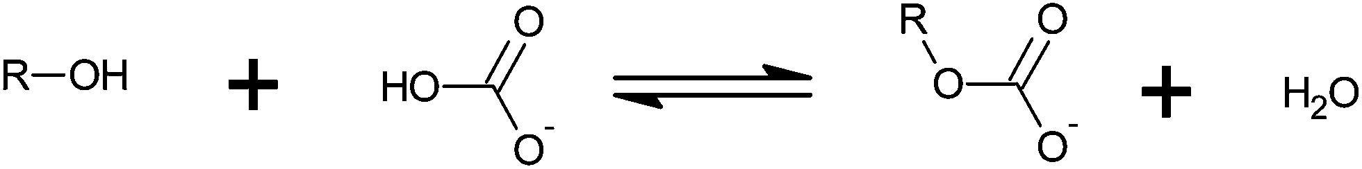 | ||
| Scheme 1 Formation of a HECA from the hydroxy compound and bicarbonate. | ||
In Scheme 1, if R is an alkyl group, the term MAC applies. However, sugars, polyols, and other hydroxy compounds may also react with bicarbonate. In these cases, HECA sounds more appropriate. Although HECA is a broader term, MAC is sometimes used instead.
The former studies about the MACs were essentially carried out by monitoring pH changes during the hydrolysis of their salts, because of the slow conversion of the MAC into bicarbonate and then in CO2.1,5–7 Richardson observed, by 13C NMR, the formation of monoethyl carbonate (MEC) in presence of a small amount of water.8 Capillary electrophoresis with capacitively coupled contactless conductivity detection (CE-C4D) allowed a systematic study about several HECAs. Ionic mobilities, diffusion coefficients, and ionic radii of MACs were initially obtained as well as kinetic and thermodynamic constants for the formation reaction in aqueous medium.2 In a subsequent work, the presence of MEC in beer and other drinks were confirmed.3 HECAs of polyols and sugars were then studied.4 This study suggested that HECAs of biological compounds, such as sugar and sterols, could be formed in biological conditions. Because of the complexity of the matrix and the anticipated low concentration of the HECAs, electrospray ionization/mass spectrometry (ESI-MS) was then introduced as an alternative technique.9 The CO2 loss at low collisional energy was the most common behaviour of the MACs in the gas phase. Although ESI-MS alone did not allow the same good quantitation approach developed for CE-C4D, sensitivity and selectivity were improved, which stimulated the development of the herein introduced CE-MS/MS method.
2. Experimental
2.1 Instrumentation
The CE equipment was an Agilent 7100 coupled to a 6430 triple-quad mass spectrometer (Agilent Technologies, Santa Clara, CA, USA) equipped with an ESI source. Nitrogen was used as nebulizer gas (15 psi) and as carrier gas at a flow rate of 4 L min−1 at 120 °C. The mass spectrometer was operated in multiple reactions monitoring (MRM) mode. Inlet capillary voltage, fragmentor, cell accelerator voltage, and collision cell voltage were set to 4 kV, 20 V, 3 V, and 0 V, respectively. Dwell time was set to 200 ms.A thermally isolated case (Fig. 1) was made in the laboratory using poly(methyl methacrylate) (PMMA). The inner surface was covered with 5 mm polyethylene foam. A liquid-cooled radiator H55 (Corsair Components, Fremont, CA, USA) coupled to a water chiller MA-184 (Marconi, Piracicaba, SP, Brazil) was used to control the temperature inside the case. Most of the CE silica capillary was covered with a 4 mm i.d., 6 mm o.d. polyurethane (PU) tube and an external 11 mm o.d. silicone tube. Two PVC adaptors allowed the capillary and the two plastic tubes be aligned. Compressed air (60 psi) was dried and thermostated inside the case before it was injected inside the PU tube, which allowed the return of the air to the case through the external silicone tube. The inner pressure of the case was naturally released through the door of the case. The capillary inside the plastic tubes was aligned with the inlet vial of CE equipment through the use of a new CE cartridge also made with laser-cut PMMA parts.
 | ||
| Fig. 1 Pictorial diagram and pictures of the CE-ESI coupling. A thermally isolated case (a) encompasses the outside part of the silica capillary (b) from the CE cartridge (c) to the ESI probe (d). A 12 V fan (e) forces air through a radiator that is fed with temperature-controlled water (f). A compressed air flow (g) passes through a copper tube inside the case and then to the inner PU tube (h) accompanying the capillary until the CE vial (i). The air flows back to the case through the external silicone tube (h). Part of the sheath liquid capillary (j) and nebulizer nitrogen flow (k) is also kept inside the thermostating case. The most important heat source is the ESI block (l), which is kept warm by the hot drying gas used to produce ions in gas phase. | ||
2.2 Materials and methods
All the reagents were acquired from the Sigma-Aldrich (St. Louis, MO, USA), except the NaHCO3 and NH4OH purchased from Merck (Darmstadt, Germany). All aqueous solutions were prepared with 18 MΩ cm deionized water (Milli-Q Direct, Millipore, Molsheim, France). Stock solutions of 1 mmol L−1 caffeine, 2.7 mmol L−1 trichloroacetic acid, and 200 mmol L−1 NaHCO3 were prepared by dissolution with deionized water.Solution of MACs was prepared with 16 mmol L−1 NaHCO3, 25 mmol L−1 3-pentanol, 250 mmol L−1 1-butanol, 430 mmol L−1 2-propanol, and 430 mmol L−1 ethanol in deionized water and then left to react for 2 hours before use. The BGE was 60 mmol L−1 propionic acid and 120 mmol L−1 NH3 in acetonitrile–water 1![[thin space (1/6-em)]](https://www.rsc.org/images/entities/char_2009.gif) :4 (v/v). The sheath liquid for the ESI source was prepared diluting 60 times this BGE with methanol–water 1:1 (v/v).
:4 (v/v). The sheath liquid for the ESI source was prepared diluting 60 times this BGE with methanol–water 1:1 (v/v).
The MEC calibration solutions were made with different amounts of NaHCO3 and ethanol. In this case, the BGE was 10 mmol L−1 propionic with and 20 mmol L−1 NH3 (final pH 9.2). The sheath liquid for the ESI source was prepared diluting 20 times this BGE with methanol–water 1:1 (v/v).
The experiment about the temperature control was carried out with a solution of MEC prepared by mixing ethanol, caffeine, TCA, and bicarbonate solutions for final concentrations of 430 mmol L−1, 13 μmol L−1, 180 μmol L−1, and 16 mmol L−1, respectively. The solution was used 2 hours after preparation.
The experiments were carried out using 58 cm long, 50 μm i.d., 360 μm o.d. fused-silica capillary (Agilent, Redmond, OR, USA). The capillary was preconditioned by washing with 0.1 mol L−1 NaOH solution (10 min), deionized water (10 min), and BGE (10 min). The samples were hydrodynamically injected at 100 mbar for 20 s. During the electrophoretic run (at 23 kV), pressure of −37 mbar was applied to the inlet vial to compensate the ESI suction effect.10
3. Results and discussion
3.1 The CE-MS interface and conditioning of the capillary
The usual coupling of CE and MS equipments results in a configuration in which part of the silica capillary is exposed to the laboratory environment. Therefore, the region around the capillary has neither good temperature control nor efficient air advection. Although this situation is not suitable for electrophoresis experiment as a whole, it is particularly undesirable for unstable species such as the HECAs. We have shown that the hydrolysis of the HECAs during the migration process is significant. The previously used double C4D allowed the kinetic study based on this behaviour.2,4 In some cases – such as for fructose carbonate – the hydrolysis occurs in so much extent that no peak is detected at the second C4D (ca. 40 cm) after a few minutes of migration process.4To improve the control on the temperature and the advection of the air around the capillary, a case was made to confine the silica capillary (Fig. 1). The inner side of the case was covered with polyethylene foam to improve thermal isolation. The most significant source of heating is the ESI aluminium block beneath the case, because of the continuous flow of the hot drying gas used to produce ions in gas phase. The compressed air inside the PU tube ensures the temperature control of the silica capillary. The advection cause by a flow of 2 L min−1 was enough to minimize the Joule heating in all the experiments. However, to keep uniform the temperature, the flow must be raised to 6 L min−1 in experiments carried out at 12 °C for a laboratory at 24 °C.
3.2 The development of the BGE and experimental conditions
The previous studies on CE-C4D and ESI-MS were used as the basis for new the CE-MS method. The pH of the background electrolyte (BGE) was chosen above 7, because of the faster decomposition of the HECAs in acid medium.3,4 Although the reversal of the electroosmotic flow (EOF) was used in some of the previous experiments,2 no EOF modifier was used to prevent the contamination of the ESI source. For the positive voltage being applied at the injection point and pH 9.2, the EOF was high enough to allow the migration of MEC – the faster MAC in the present study and, then, the slower one in the counter-EOF mode – towards the ESI source. Buffering was obtained with the equilibrium NH3/NH4+, which also prevents an excessive deposition of solids inside the ESI source. The co-ion in the BGE was propionate. Although formate and acetate tend to generate smaller amounts of solid residue, they cause greater suppression of the analytes ions during the ESI process. Therefore, propionate provides a good balance between sensitivity and usability of the method. Tests were carried out using pure water and mixtures of water and acetonitrile as the solvent for the BGE.The BGE diluted with a mixture of water and methanol was used as the sheath liquid. Despite the low buffering capacity of the diluted BGE, sensitivity was improved because of the low ion content. Methanol eases the droplets formation because the lowering of the surface tension. However, it precludes the detection of monomethyl carbonate, because it may be previously available in the reagent or may be formed by absorption of CO2 from the air.9
The fragmentation of a MAC at low collisional energy yields the corresponding alkoxide by loss of CO2.9 This reaction occurs even when the energy at the collisional chamber (the hexapole between the two separation quadrupoles) is set to 0 eV. This is an important feature of MACs, because carboxylate usually fragment at higher energies yielding the corresponding carbanion. However, loss of CO2 at 0 eV is not an exclusive feature of MACs, because some carboxylates – sometimes in higher concentration in the real sample – form carbanions that are stabilized by either resonance or presence of electronegative heteroatoms in the structure. Therefore, the detection in the MRM mode for M− → [M − 44]− was adopted to improve the selectivity of the CE-MS method. However, the presence of a peak in the corresponding electropherogram was carefully investigated.
3.3 The temperature control and the hydrolysis of MEC
The migration process of a MAC depends on the temperature in two different ways. The first one is effect of the temperature on the hydrolysis reaction: the higher the temperature, the larger the extent of the hydrolysis reaction. Therefore, the higher the temperature of the BGE, the smaller should be the peak area. On the other hand, there is a dependence of viscosity the BGE on temperature. Due to this effect, the higher the temperature, the smaller is the migration time and, consequently, the smaller is the time in which the MAC is exposed to the hydrolysis before detection. The combination of these two antagonistic effects is demonstrated in Fig. 2. For low temperatures, there is some equilibrium between the effects on reaction rate and migration time. Above ca. 20 °C, the reducing on the migration time is not enough to compensate the increasing decomposition of the MAC by hydrolysis. As a result, the peak area (A) at 34 °C is ca. of 1/10 of the area for 20 °C. Therefore, 20 °C was adopted for the posterior experiments because of the good compromise between sensitivity and analysis time.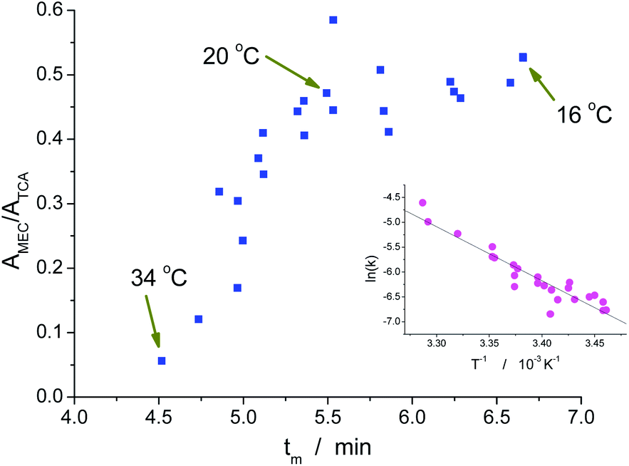 | ||
| Fig. 2 Relative area versus migration time. TCA, a stable species, was used as internal standard. The inset is the Arrhenius plot, which slope was used to estimate the activation energy of the hydrolysis reaction of MEC. | ||
The results obtained at different temperatures were also used to estimate the activation energy for the hydrolysis of MEC. The kinetic constant for the reverse reaction shown in Scheme 1 (kh) was previously determined as 1.99 × 10⁻⁵ L mol−1 s−1 at 20 °C and for solution mainly aqueous.2 In the present case, water was the exclusive solvent used in the BGE. Therefore the constant to be considered for the first order reaction of hydrolysis was 1.11 × 10⁻³ s−1. Taking into account that the relative area is proportional to the concentration of MEC, the relative area without hydrolysis (A0) from the experiments carried out at temperatures close to 20 °C could be estimated by:
| A = A0e−khtm | (1) |
Despite the importance of such a result for kinetic studies, it also represents an additional test for the temperature control of the system. As one can see in Fig. 1, a portion of the capillary is inside the probe used by the ESI source. This part – made of stainless steel and in direct contact with the aluminium block of the ESI source – has an intermediary temperature and could make uncertain the temperature of the silica capillary inside it. However, the linear shape of the Arrhenius plot suggests that the temperature is uniform along the entire capillary. Most probably, the fact that the nebulizer gas tube is partially accommodated inside the box contributes positively for this temperature control inside the probe.
3.4 The separation of a mixture of MACs
Fig. 3 shows the separation of a mixture of NaHCO3, four different alcohols, trichloroacetate (TCA) as internal standard and caffeine as an EOF marker. The alcohols were randomly selected to include some primary and secondary alcohols. Obviously, the greater the number of analytes, the smaller the time spent in monitoring each one, and consequently smaller the SNR. As expected, MEC was the last analyte in the migration process against the EOF. MRM baseline for m/z 131 → 87, 117 → 73, 103 → 59, and 89 → 45 – which were used to detect mono-3-pentyl carbonate (MPeC), mono-1-butyl carbonate (MBC), mono-2-propyl carbonate (MPrC), and MEC, respectively – shows no significant production of ions other than the analytes. Although the separation using 100% aqueous medium is possible, the addition of acetonitrile tends to improve the shape of the peaks. | ||
| Fig. 3 Electropherograms of a mixture containing MACs. The sample was an aged solution containing 13 μmol L−1 caffeine (Caf), 180 μmol L−1 TCA, 16 mmol L−1 NaHCO3, 25 mmol L−1 3-pentanol, 250 mmol L−1 1-butanol, 430 mmol L−1 2-propanol, and 430 mmol L−1 ethanol. CE conditions: the BGE was 60 mmol L−1 propionic acid and 120 mmol L−1 NH3 in acetonitrile–water 1:4 (v/v); the temperature was 20 °C. ESI conditions: the sheath liquid (6.0 μL min−1) was the BGE diluted 1:60 in water–methanol 1:1. MS conditions: MRM m/z 195 → 138 for protonated caffeine, m/z 161 → 117 for TCA, m/z 131 → 87 for mono-3-pentyl carbonate (MPeC), m/z 117 → 73 for mono-1-butyl carbonate (MBC), m/z 103 → 59 for mono-2-propyl carbonate (MPrC), and m/z 89 → 45 for monoethyl carbonate (MEC). Negative ion mode was used for all the analytes but caffeine. For sake of visualization, the signal for protonated caffeine and TCA was attenuate 8 times and all the spectra were vertically shifted. | ||
3.5 Quantitation of HECAs
Quantitation of HECAs is a challenging task because of the well-known hydrolysis, i.e., just after the preparation of a solution containing, for instance, CH3CH2OCO2Na, hydrolysis takes place before any practical use of the standard solution. Moreover, during the separation, hydrolysis consumes the analyte making uncertain its concentration at the detection point.In the previous studies, the quantitation of HECAs was only possible because of a peculiar feature of CE with conductivity detection, which allows one to substitute the analyte with another species of same mobility for sake of calibration.2–4 Unfortunately, there is no equivalent approach for CE-MS. However, at the present stage of knowledge about HECAs, any quantitative method represents an advance for the area. Therefore, the following procedure was established.
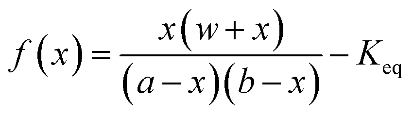
If the experimental conditions are kept constant, it is a very reasonable approximation to consider that the amount of a HECA being transferred to the gas phase at the ESI source is proportional to the concentration of HECA at the sample that was injected. In fact, the most important source of error is the hydrolysis and, thus, the control over temperature and migration time becomes important. The next step is the knowledge of the concentration at the solutions being used for calibration. In this point, the equilibrium constant (Keq), previously determined by CE-C4D, was used. Considering the preparation of a solution by mixing a known amount of alcohol, bicarbonate, and water, the HECA concentration at the equilibrium is the root of the function f(x):
 | (2) |
Fig. 4 shows a calibration curve for MEC using TCA as internal standard. Solutions were prepared with 7 initial concentrations of NaHCO3 (0.25, 0.5, 1, 2, 4, 8, 16 mmol L−1) and 5 concentrations of ethanol (1, 5, 10, 20, and 40% v/v) resulting in 35 samples, which were analysed in triplicates. These concentrations cover the expected levels of ethanol and bicarbonate in common samples such as fermentation processes, blood of a drunken person, and alcoholic beverages.
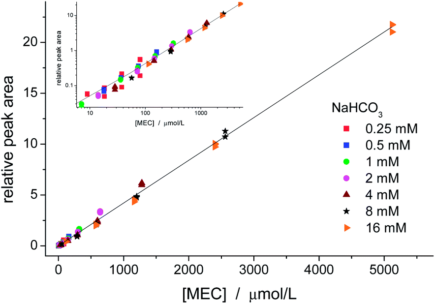 | ||
| Fig. 4 Calibration curve for MEC using TCA as internal standard. Both linear and logarithm (inset) graphs show good linearity and no significant difference among the sets prepared with different levels of ethanol (1, 5, 10, 20, and 40% v/v) and bicarbonate. The values for intercept and slope and standard errors were, respectively, 0.003 ± 0.027 and (4.202 ± 0.024) L mmol−1. R2 = 0.9967 for N = 105. | ||
Good linearity was obtained for the entire range. There was no significant difference among the data groups, which demonstrates that the calibration curve may be prepared by changing either the amount of one of the reagents or both of them. The intercept (0.003 ± 0.027) was not significantly different from zero. The LOD (SNR = 3) for MEC was estimated as 0.2 μmol L−1, which is ca. of two orders of magnitude lower than the LOD obtained by CE-C4D.
Using the same calibration approach to the MACs shown in Fig. 3, the LODs were estimated as 0.2, 0.5, 2, and 1.3 μmol L−1 for MPeC, MBC, MPrC, and MEC, respectively. It is worthy of note that LOD for MEC is higher in this case, because the ESI source was tuned for the longer chain MACs. In Fig. 3, MPeC is the smallest peak, because of the low solubility of the 3-pentanol. However, its LOD is as low as the one for MEC under optimized condition.
This finding is in agreement with our previous experiments with direct injection of MAC solutions in ESI-MS.9 We have observed an increasing trend in production of gas-phase MAC ions as the carbonic chain increases. However, when direct injection is used, a clear understanding about this behaviour is precluded because of the possible contribution of both the alcohol and its MAC to the efficiency of ionization. In the present case, the alcohol is not present during the detection, because it is migrating with the EOF. Therefore, the difference in sensitivities may be attributed to the nature of the MACs, and our previous hypothesis regarding the movement of the long-chain MACs to the surface of the electrosprayed droplet is supported.9
4. Conclusions
The improvements on the temperature control of the capillary allowed the development of a CE-MS method for detection and quantitation of some MACs. Although our initial attempts using the regular CE-MS coupling allowed the detection of MACs, the results were uncertain, because very often the peaks were broader or even absent. This behaviour may be attributed to the hydrolysis of the MAC, which decomposes the analytes in different extents depending on the Joule heating of the capillary and the uncontrolled advection of the air around it. The strict control on the temperature inside the capillary is particularly important for this class of analytes, but it can also improve the development of other CE-MS methods, because mobility depends on temperature, and, therefore, an improvement of the migration time may be obtained by controlling the capillary temperature.Compared to CE-C4D, the new method tends to give better LODs. However, the former method is still advantageous because of the ability of quantitation without previous information about the equilibrium constant, as demanded by the present CE-MS method. Therefore, an interesting approach is the combination of the two techniques: CE-C4D methods for the determination of the kinetic and thermodynamic properties, which are then applied to more selective and sensitive CE-MS methods.
Acknowledgements
This work was supported by FAPESP (grant 2012/06642-1). C. L. L. thanks CNPq (researcher fellowship 304239/2010-0). D. T. R. V. and V. B. S. thank FAPESP (fellowships 2011/02156-2 and 2013/14993-1).Notes and references
- N. F. Miller and L. O. Case, J. Am. Chem. Soc., 1935, 57, 810–814 CrossRef CAS.
- D. T. R. Vidal, T. Nogueira, R. M. Saito and C. L. do Lago, Electrophoresis, 2011, 32, 850–856 CrossRef CAS PubMed.
- M. R. Rossi, D. T. R. Vidal and C. L. do Lago, Food Chem., 2012, 133, 352–357 CrossRef CAS PubMed.
- C. L. do Lago, D. T. R. Vidal, M. R. Rossi, G. M. Hotta and E. T. da Costa, Electrophoresis, 2012, 33, 2102–2111 CrossRef CAS PubMed.
- Y. Pocker, B. L. Davison and T. L. Deits, J. Am. Chem. Soc., 1978, 100, 3564–3567 CrossRef CAS.
- C. K. Sauers, W. P. Jencks and S. Groh, J. Am. Chem. Soc., 1975, 97, 5546–5553 CrossRef CAS.
- I. Noring, A. Jensen and C. Faurholt, Acta Chem. Scand., 1952, 6, 404–410 CrossRef CAS PubMed.
- D. E. Richardson, H. R. Yao, K. M. Frank and D. A. Bennett, J. Am. Chem. Soc., 2000, 122, 1729–1739 CrossRef CAS.
- D. T. R. Vidal, M. A. Santana, G. M. Hotta, M. N. Godoi, M. N. Eberlin and C. L. do Lago, RSC Adv., 2013, 3, 18886–18893 RSC.
- C. L. do Lago, D. T. R. Vidal, K. J. M. Francisco and V. B. dos Santos, Electrophoresis DOI:10.1002/elps.201300651.
- R. N. Mioshi and C. L. do Lago, Anal. Chim. Acta, 1996, 334, 271–278 CrossRef CAS.
Footnote |
| † The roots may be derived analytically for two cases Keq = 1 and Keq ≠ 1. Despite the greater complexity for implementation, numerical solution is better, because it applies to any value of Keq. |
| This journal is © The Royal Society of Chemistry 2014 |