Nucleating effect of multi-walled carbon nanotubes and graphene on the crystallization kinetics and melting behavior of olefin block copolymers

Siduo Wu, Hui Li, Guangsu Huang* and Jinrong Wu*
College of Polymer Science and Engineering, State Key Laboratory of Polymer Materials Engineering, Sichuan University, Chengdu 610065, People's Republic of China. E-mail: guangsu-huang@hotmail.com; kajion@hotmail.com

Received 28th February 2014 , Accepted 7th April 2014

First published on 8th April 2014


Abstract

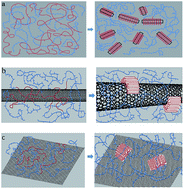
Crystallization is of primary importance to the properties of olefin block copolymers (OBCs). In the present work, multi-walled carbon nanotubes (MWCNTs) and graphene are used as nucleating agents for the crystallization of OBC. Thus nanocomposites of OBC filled with MWCNTs and graphene were prepared by solution blending. Differential scanning calorimetry (DSC) tests were carried out to study the effect of CNTs and graphene on isothermal crystallization of OBC; polarizing optical microscopy (POM), and wide-angle X-ray diffraction (WAXD) were used to study the morphology and crystal structure of OBC and its nanocomposites. It is found that both MWCNTs and graphene act as effective nucleating agents that significantly shorten the induction period of crystallization and increase the crystallization rate of OBC, exhibiting a remarkable decrease in the Avrami exponent n, surface folding energy σe and crystallization activation energy ΔE. These two carbon-based fillers both act as templates for hard block chains of OBC to form an ordered structure on the surface of nanoparticles during the induction period, bringing about some increase in equilibrium temperature. With the decrease in n, σe and ΔE not as remarkable as those of MWCNTs, graphene exhibited weaker nucleating ability than MWCNTs which might be due to strict lattice matching. The melting process of OBC and its nanocomposites are also studied; the nanocomposites exhibit two melting peaks at higher crystallization temperature which mainly refer to the melting of the crystals with different crystal sizes and perfection during heating, which is not observed for neat OBC.


1. Introduction

The INFUSE® olefin block copolymers (OBC) were developed by Dow Chemical Company using a chain shuttling technology which employs two catalysts, one forming hard or crystalline ethylene blocks with low octene concentration and the other forming amorphous blocks with high incorporation of octene in the ethylene chain. Being multi-block copolymers with a statistical multi-block architecture with a distribution of block lengths and a distribution of the number of blocks per chain, OBC imparts better performance in many applications which is attributed to higher crystallization rate, higher melting temperature and highly ordered crystalline morphology contributed by hard blocks and low glass transition temperature contributed by soft blocks.1,2

One of the key parameters of OBCs is octene content, the distribution of which brings about hard blocks and soft blocks in OBC matrix, and mesophase separation as well. As has been classified by Loo et al.,3 the crystallization behavior of block copolymer can be breakout, templated crystallization and confined crystallization, depending on the interblock segregation strength. Also, the morphology of OBCs are determined by the competition between mesophase separation and crystallization of hard blocks, though the nature of crystallization are similar.4,5 Charles C. Han et al.4 investigated stereo-hindrance effect on crystallization of OBCs caused by mesophase separation, and found that the crystal lamellae were confined in the mesophase-separated domains, while all OBCs can form nearly the same crystalline morphology if the mesophase separation is suppressed. The mesophase separation transition and stereo-hindrance effect are both enhanced as octene content increases, which reveals that in OBC with higher octene content, the hard and soft blocks are more immiscible. Same conclusion was drawed by John M. Dearly et al.6 from rheological evidence. Epitaxy-induced crystallization studies of OBCs by Dujin Wang et al.7 showed that OBCs can exhibit breakout morphology in the presence of benzoic acid, showing remarkable difference from confined morphology in bulk OBCs.

Epitaxy can improve adhesion, compatibility and mechanical properties by growing guest crystals on the surface of base materials of another phase, which requires geometric matching between guest crystals and base materials, and the surface of the latter can offer nucleation sites.8–11 Epitaxial crystallization of OBC on isotactic polypropylene and high-density polyethylene which act as templates for crystallization and offer nucleation sites was also studied by Dujin Wang et al.,12 they found that higher octene concentration difference (ΔC8) has the same effect as stronger nucleation ability of base materials on epitaxial morphology which exhibits isolated crystalline domains. Nano fillers can also work as templates for crystallization and act as nucleating agents, yet these effects of nano fillers on OBCs has not been studied.

As a potential substitute for traditional thermoplastic elastomers such as styrene–butadiene–styrene (SBS) triblock copolymer, OBC still have its shortcomings, e.g., a relatively low tensile strength, say, only around 4.98 MPa for neat OBC, significantly lower than 28 MPa for neat SBS.13,14 To improve the mechanical properties of OBC, it's a common sense to add filler to the polymer matrix. Since the mechanical properties of OBC strongly depend on the crystallization of hard blocks, it is of primary significance to study the influence of filler on the crystallization behaviors of OBC. However, up to date, no work on this subject has been reported to the best of our knowledge, although many pre-existing investigations on OBCs have been done to gain a better understanding of this new material.

Carbon based nanomaterials, such as multi-walled carbon nanotubes (MWCNTs) and graphene, have attracted tremendous attention in recent years, due to their extremely high aspect ratio, small dimension, superior mechanical and electrical properties.15–21 Some previous works have found that MWCNTs and graphene could significantly change the crystallization behaviors of polymers.22–28 For example, MWCNTs can induce hybrid crystalline structure like nano-hybrid shish-kebab (NHSK), thus serving as shish when polymer lamellae periodically decorates the surface of MWCNTs as kebabs, which is reported in polymer matrices like high-density polyethylene (HDPE),23,24 nylon 6,6,24,29 polyvinylidene fluoride (PVDF).30 Some works on graphene induced polymer crystallization were carried out in recent three years, proving graphene as an efficient nucleating agent.25–28 Though not strongly concentration dependent, graphene exhibits a synergistic effect with shear flow on inducing the crystallization of α-crystals of iPP.26 Some other studies also demonstrate the nucleation ability of graphene, but it is found that introducing graphene does not change the crystal form of polymer matrix.27,28 A comparative study in poly(L-lactide) (PLLA) indicates that the inducing ability of graphene is not as strong as MWCNTs due to geometric and dimensionality difference.31

Both made up of graphite layers, graphene and MWCNTs have the same fundamental structural unit, while the difference lies in dimensionality that graphene has a two-dimensional nanoplate-like structure and MWCNTs can be considered as one-dimensional nanolines. Both being proved as effective heterogeneous nucleating agents, these two carbon allotropes are of different but unique morphological structures, which inspires us to perform a comparative study on the different inducing effects of these nanoparticles on the crystallization of OBC.

In the present study, a method of mixed solvents solution blending was used to prepare OBC nanocomposites with the filler contents of 0.05% and 0.1%. The inducing effects of MWCNTs and graphene on the crystallization of OBC have been investigated by DSC, PLM and WAXD. The nucleating mechanism and crystallization kinetics of OBC nanocomposites were discussed in order to help us gain a better understanding of inducing and templating mechanisms of nanoparticles in polymer nanocomposites.

2. Experimental

2.1 Materials

The OBC (9500) used in this study are kindly provided by The Dow Chemical Company. The corresponding information on the overall density, weight-averaged molecular weight, molecular weight distribution is listed in Table 1. MWCNTs of outer diameter ∼20 nm, length 10–30 μm and specific area 400 m2 g−1 were purchased from Chengdu Organic Chemicals Co., Ltd., R&D Center for Carbon Nanotubes of the Chinese Academy of Science. A transmission electron microscopy (TEM) image of the MWCNTs is shown in Fig. 1a. Graphene of diameter 0.8–3 μm, thickness 0.8–1.2 nm and single layer ratio 99.8% are provided from Nanjing Jcnano Technology Co., Ltd. An atomic force microscopy (AFM) image of the graphene is shown in Fig. 1b. Xylene (AR grade) and N,N-dimethyl formamide (DMF) (AR grade) were purchased from Chengdu Kelong Chemical Reagent Factory (China).
Table 1 Sample information of OBC
Properties Density (g cm−3) Mw (g mol−1) Mw/Mn Tm (°C) Tg (°C)
Values 0.878 82[thin space (1/6-em)]600 2.3 122 −45


image file: c4ra01776e-f1.tif
Fig. 1 TEM image of MWCNTs (a) and atomic force microscopy image of graphene (b).

2.2 Preparation of OBC nanocomposites

MWCNTs were stirred in nitric acid (70%) at room temperature for 48 h, and washed several times with deionized water until the filtrate showed neutral pH to remove the amorphous carbon and metallic catalyst nanoparticles before use. Graphene was used as received. The method of mixed-solvent solution blending was applied to prepare OBC nanocomposites with different MWCNTs and graphene contents. Take the OBC/MWCNTs nanocomposite with 0.05 wt% MWCNTs as an example, the procedure was as follows: OBC (10 g) was dissolved in xylene (160 ml) at 130 °C by magnetic stirring in an oil bath. Purified MWCNTs (5 mg) were dispersed in DMF and sonicated for 2 h. The DMF/MWCNTs suspension was added dropwise into the xylene/OBC solution after sonication and the mixture was continuously stirred for another 30 min. The mixture was transferred to a rotary evaporator and dried in a vacuum oven at 70 °C for 24 h to remove residual solvent. Nanocomposite samples were molded at 190 °C into films of ∼1 mm. The OBC nanocomposites with 0.05% and 0.1% MWCNTs were designated as OBC/CNT005 and OBC/CNT01, respectively, while those with 0.05% and 0.1% graphene are named as OBC/G005 and OBC/G01, respectively.

2.3 Characterization

The dispersion state of MWCNTs and graphene within the OBC matrix was observed by a transmission electron microscope (TEM, FEI Tecnai G2 F20 S-TWIN) at an accelerating voltage of 200 kV. Ultra-thin sections were prepared using a Leica Ultracut UCT ultramicrotome with a diamond knife at −100 °C.

Measurements of differential scanning calorimetry (DSC) were performed on Q200 (TA instruments) under isothermal and nonisothermal conditions. The weights of the samples were in the range of 7–8 mg and all the DSC measurements were performed under nitrogen atmosphere. The isothermal crystallization and melting process of neat OBC and its nanocomposites were performed as follows: The samples were heated at 50 °C min−1 to 280 °C and maintained for 5 min to attain a homogeneous melt. This temperature was chosen because mesophase separation, which has a remarkable restrain effect on the crystallization behavior of OBC, is suppressed thus a homogeneous phase can be obtained at the temperature of 280 °C.4 Then the samples were cooled at 70 °C min−1 to a predetermined crystallization temperature, Tc, in the range of 110–120 °C, and maintained at Tc till the heat flow went flat which indicated the completion of crystallization. After this, the samples were heated to 280 °C. A new specimen was used as the for each isothermal test.

The dynamic mechanical properties of OBC were tested by dynamic mechanical analysis (DMA Q800, TA instruments) using a dual cantilever clamp and a testing method of temperature ramp-frequency sweep with a heating rate of 3 °C. The oscillation strain amplitude was set at 25 μm with a frequency of 1 Hz. Tg obtained by DMA test is listed in Table 1.

Synchrotron X-ray characterization. Specimens WAXD were isothermally crystallized at the target temperature and quenched to ambient temperature using a heating stage. WAXD measurements were carried out at BL16B1 at the Shanghai Synchrotron Radiation facility (SSRF), Shanghai, China. The wavelength of the synchrotron radiation was 0.124 nm. 2D WAXD patterns were recorded every 60 s by Mar345 CCD (MAR USA) detector system with a resolution of 2048 × 2048 pixels (pixel size: 79 × 79 μm2). The sample-to-detector distance was around 135 mm for WAXD (calibrated by an yttrium oxide (Y2O3) standard). All X-ray images were corrected for background scattering, air scattering and beam fluctuations.

Polarizing optical microscopy. Polarized light optical micrographs were obtained with a 12 POLS polarizing microscope (Leica Microsystems GmbH) equipped with a hot stage and CCD camera. Specimens were made by sandwiching a piece of pellet between two glass slides and placing the glass slides on the hot stage, after heating at 200 °C for 5 min under minimal pressure, the specimens were quickly cooled to specified crystallization temperature.

3. Results and discussion

3.1 Crystallization kinetics

TEM image of OBC/CNT01 and OBC/G01 are shown in Fig. 2. In Fig. 2a, several single MWCNTs are dispersed in OBC matrix, and in Fig. 2b, graphene sheets lie flat with some wrinkles, both pictures show good dispersion state of nano fillers.
image file: c4ra01776e-f2.tif
Fig. 2 TEM image of OBC/CNT01 (a) and OBC/G01 (b).

During crystallization, the hard blocks in OBC chains are long enough to form chain-folded lamellar crystals, and these crystallizable hard blocks need to segregate and organize themselves into space-filling spherulites, while the soft blocks were forced into interlamellar regions.32 As is reported, crystallization always occurs with mesophase separation simultaneously and competitively, and the latter has remarkable restraining effect on the crystallization of hard blocks.4,5 In this study, the samples for DSC isothermal tests were maintained at 280 °C and rapidly cooled to the crystallization temperature to avoid the effect of mesophase separation.4 The isothermal crystallization kinetics were studies at various temperatures near Tc. The relative crystallinity xt is given as

 
image file: c4ra01776e-t1.tif(1)
where Xt and X are the crystallinity at time t and the time of completion, respectively. dH/dt is the heat evolution rate, ΔHt is the total heat generated at time t, and ΔH is the total heat generated at completion. The halftime of crystallization (t1/2), which can be considered as a reference of the crystallization rate, is defined as the time it takes to reach xt = 0.5.

The isothermal crystallization kinetics of polymers can be well approximated by Avrami equation, the classic form of which is given as:33

 
1 − xt = exp(−ktn) (2)
where k is the crystallization rate constant and n is the Avrami exponent depending on the crystal growth geometry and nucleation mechanism.34,35 Eqn (2) can be transformed into the double logarithmic form as
 
ln[−ln(1 − xt)] = n[thin space (1/6-em)]ln[thin space (1/6-em)]t + ln[thin space (1/6-em)]k (3)

From the expression we can see that if this Avrami approach is efficacious, the plot of ln[−ln(1 − xt)] versus ln[thin space (1/6-em)]t should be linear with a slope of n and an intercept of ln[thin space (1/6-em)]k. Results from Fig. 4 show that the Avrami plots for neat OBC are close to linear. For OBC nanocomposites, the straight lines are obtained with a relative crystallinity ranged from 1% to 65%. In the linear range, the samples are under primary crystallization. Beyond the linear range, the deviation is attributed to secondary crystallization. From the linear part of these plots from Fig. 3, the Avrami exponent n and crystallization rate constant k can be obtained. The values of n and k for neat OBC and OBC composites at various temperatures are presented in Table 2, together with the induction period of crystallization (ti) and the half-crystallization time (t1/2).


image file: c4ra01776e-f3.tif
Fig. 3 Avrami plots for isothermal crystallization: (a) neat OBC (b) OBC/CNT005 (c) OBC/CNT01 (d) OBC/G005 (e) OBC/G01 (xt related to each Avrami plots is from 1% to 99.6%).
Table 2 Kinetics parameters of the isothermal crystallization for neat OBC and its composites
  Tc (°C)
120 118 116 114 112 110
Neat OBC t1/2 (min)   79.68 34.23 10.83 5.62 3.19
ti (min)   39.4 17.2 5.64 2.93 1.65
n   2.84 2.91 2.97 2.9 2.9
k   2.2 × 10⁻⁶ 2.51 × 10⁻⁵ 5.65 × 10⁻⁴ 0.00445 0.0241
OBC/CNT005 t1/2 (min) 8.49 3.22 1.44 0.758 0.513  
ti (min) 3.39 1.39 0.576 0.275 0.181  
n 2.77 2.75 2.30 1.99 1.77  
k 0.00201 0.0256 0.292 1.18 2.28  
OBC/CNT01 t1/2 (min) 7.29 2.36 1.10 0.71 0.435  
ti (min) 3.19 1.06 0.46 0.27 0.16  
n 2.55 2.41 2.13 1.87 1.71  
k 0.00456 0.0874 0.558 1.32 2.90  
OBC/G005 t1/2 (min) 11.9 3.75 1.88 1.08 0.681  
ti (min) 6.21 1.69 0.64 0.421 0.29  
n 2.91 2.25 2.38 2.18 1.99  
k 3.20 × 10⁻⁴ 0.0474 0.182 0.566 1.41  
OBC/G01 t1/2 (min) 9.3 3.34 1.46 1.07 0.74  
ti (min) 3.56 1.70 0.654 0.409 0.24  
n 2.97 3.15 2.59 2.20 1.81  
k 8.69 × 10⁻⁴ 0.0153 0.277 0.585 1.10  


The ti is defined as the time at which the relative crystallinity reaches 10% and can be used to reveal the inducing ability of nanofiller. The t1/2 is defined as the time at which the crystallization reaches 50%, which, as well as k, can directly reflect the overall crystallization rate. From Table 2, we can see that the ti and t1/2 of OBC/MWCNTs nanocomposites are far lower than those of neat OBC. For example, ti = 1.39 min, t1/2 = 3.22 min for OBC/CNT005 at 118 °C, significantly lower than corresponding values of neat OBC (i.e. ti = 39.4 min, t1/2 = 79.68 min). At the same time, the addition of nano fillers remarkably enhance k for the nanocomposites (e.g., at 118 °C, k of OBC/CNT005 is 0.0256, nearly four orders of magnitude higher than that of neat OBC). These phenomena suggest that MWCNTs provide additional nucleation sites for OBC crystals, thus reduce the induction period and accelerate the crystallization of OBC. For OBC/graphene nanocomposites, the crystallization rate is also significantly enhanced compared with that of neat OBC, which indicates that graphene can also act as effective nucleation agent for OBC. For both OBC/MWCNTs nanocomposites and OBC/graphene nanocomposites, further reduction in ti and t1/2 can be observed as the load of MWCNTs and graphene increases from 0.05 wt% to 0.1 wt%, which is due to the generation of more nucleation sites. While as is shown in Table 2, ti and t1/2 of OBC/G005 (e.g., at 120 °C, ti = 6.21 min, t1/2 = 11.90 min) is relatively longer than those of OBC/CNT005 (e.g., at 120 °C, ti = 3.39 min, t1/2 = 8.49 min), also, the crystallization rate constant k for OBC/G005 (e.g., at 120 °C, k = 0.00032) is much smaller than that of OBC/CNT005 (e.g., at 120 °C, k = 0.00201), both indicating that the inducing and nucleating ability of graphene is weaker than that of MWCNTs. The difference between MWCNTs and graphene induced crystallization will be discussed in next several parts.

Theoretically, the value of n should be an integer, while due to mixed growth and/or surface nucleation modes and two-stage crystallization, it is actually dispersed, depending on the nucleation mechanism and crystal growth geometry. The n values of neat OBC that vary from 2.84 to 2.9 are close to 3.0, which reveals that OBC hard blocks are apt to undergo three-dimensional crystallization growth with heterogeneous athermal nucleation.36,37 Incorporating MWCNTs depresses the n values (e.g., 1.77–2.77 for OBC/CNT005 and 1.71–2.55 for OBC/CNT01), compared with those of neat OBC. Higher MWCNTs content leads to lower n values, indicating that a greater amount of nucleation sites can further change the crystal growth geometry. The depression of n values is more remarkable at lower crystallization temperatures. For example, the n values of OBC/CNT005 is 1.77 at 112 °C and 2.59 at 120 °C, which means that the crystallization tends to undergo two-dimensional growth at 112 °C while simultaneous occurrence of two- and three- dimensional spherulites growth can be observed at 120 °C. For OBC/graphene nanocomposites, the n values (e.g., 1.81–2.97 for OBC/G005 and 1.99–2.91 for OBC/G01) is also obviously decreased. While this decrease is not as distinct as that of OBC/MWCNTs nanocomposites, again indicating that MWCNTs has stronger effect on the nucleation process and crystal growth geometry, which will also be demonstrated in next several parts.

3.2 Crystal morphology and X-ray crystal structural study

Fig. 4 shows the POM micrographs of OBC and OBC nanocomposites crystallized at 118 °C and 112 °C, relatively. The radius of neat OBC spherulites is not uniform, the smaller crystals are only several micrometers, while most spherulites are about 10–30 μm. The incorporation of MWCNTs and graphene reduces the size of spherulites and increases the amount of spherulites significantly. This phenomenon is more remarkable in OBC/MWCNTs nanocomposites, revealing a stronger nucleating ability, which is consistent with DSC results. Spherulites formed at higher crystallization temperature are of larger size, which is due to that higher temperature is advantageous for crystal growth while lower temperature is advantageous for nucleation. For example, spherulites of OBC/CNT01 crystallized at 118 °C are larger than those crystallized at 112 °C, which are almost beyond the resolution of POM at this magnification. Results of POM revealed that good dispersion of nano fillers can effectively influence the crystallization development and change the crystallization kinetics of OBC.
image file: c4ra01776e-f4.tif
Fig. 4 POM micrographs of isothermally crystallized samples: neat OBC at 118 °C (a) and 112 °C (b), OBC/CNT01 at 118 °C (c) and 112 °C (d), OBC/G01 at 118 °C (e) and 112 °C (f).

The crystal structure after isothermal crystallization of neat OBC and its nanocomposites is further studied by Synchrotron WAXD. Fig. 5a(1)–(3) illustrates representative 2D WAXD patterns crystallized at 118 °C. Representative 1D WAXD curves are listed in Fig. 5b, the first broad peak is the amorphous peak, while the (110) and the (200) reflections are consistent with the orthorhombic crystal structure.38 From Fig. 5b we can conclude that the presence of MWCNTs and graphene has no impact on the crystalline modification as well as crystal form of OBC at temperature range from 112–118 °C. As is shown in Fig. 5b, the shifting of OBC (110) and (200) peaks to larger angles reveals the decrease of d-spacings, which might be due to interaction between OBC and nano fillers.39,40


image file: c4ra01776e-f5.tif
Fig. 5 (a) Representative 2D WAXD patterns of neat OBC (1), OBC/CNT01 (2), OBC/G01 (3) isothermally crystallized at 118 °C. (b) Representative 1D WAXD curves of neat OBC, OBC/CNT01 and OBC/G01 isothermally crystallized at 118 °C and 112 °C.

3.3 Melting behavior and equilibrium melting temperature

Fig. 6 illustrates a series of DSC heating thermalgrams of neat OBC, OBC/MWCNTs and OBC/graphene nanocomposites after crystallization at different crystallization temperatures. It is apparent that the DSC endotherms exhibit two melting peaks at higher crystallization temperature for OBC/MWCNTs and OBC/graphene nanocomposites, while this is not observed for neat OBC. For OBC and its nanocomposites, all melting temperatures shift to higher temperature with increasing crystallization temperature, which is related to the perfection of OBC crystals and also consistent with POM results. And these two peaks tend to combine together with crystallization temperature decreasing. With WAXD results revealing that these two nano fillers exhibit no impact on crystal form, these peaks mainly refer to the melting of the crystals with different crystal sizes and perfection during heating. And from Fig. 6 we can see that the area of Peak II is much larger than that of Peak I, indicating that Peak II is corresponding to the melting of major crystal. Similar explanations of multiple endotherms can be found in other matrix like nylon and poly(ethylene teraphthalate) (PET).23,25
image file: c4ra01776e-f6.tif
Fig. 6 Melting endotherms of neat OBC, OBC/MWCNTs nanocomposites and OBC/graphene nanocomposites after isothermal crystallization at specified temperatures, recorded at the heating rate of 10 °C min−1.

The equilibrium melting temperature T0m is determined as the melting temperature of perfect polymer crystal crystallized after fully extension of the infinitely long polymer chain, which can be obtained by linear extrapolation of Tm versus Tc to the line Tm = Tc according to the theory derived by Hoffman and Weeks that can be described as the following equation.

 
image file: c4ra01776e-t2.tif(4)
where β is the thickening ratio indicating the ratio of the thickness of the mature crystal Lc to that of the initial one L*c, i.e., β = Lc/L*c.

Fig. 7 shows the plot of Tm versus Tc, showing that for both OBC and its nanocomposites, Tm values exhibit good linear relationship with Tc. From Fig. 7, we obtain the T0m values of 409.55, 411.07, 409.06, 413.47, 411.53 K and β values of 0.9466, 0.8795, 0.8937, 0.815, 0.8299 for neat OBC, OBC/CNT005, OBC/CNT01, OBC/G005 and OBC/G01, respectively, which is also listed in Table 3. The addition of MWCNTs and graphene brought some increase in T0m only with expectation of OBC/CNT01. This might be due to that crystallization on MWCNTs and graphene surface are more perfect and stable than those in neat OBC, but too much nucleating points brought by nano fillers like in OBC/CNT01, can eliminate the maturation of polymer crystals.42


image file: c4ra01776e-f7.tif
Fig. 7 Melting temperature as a function of crystallization temperature for OBC and OBC nanocomposites.
Table 3 Value of T0m, Kg, σe and ΔE of OBC and its nanocomposites
  Neat OBC OBC/CNT005 OBC/CNT01 OBC/G005 OBC/G01
T0m (K) 409.55 411.07 409.06 413.47 411.53
β 0.9466 0.8795 0.8937 0.815 0.8299
Kg (K2) 1.22 × 10⁵ 9.83 × 10⁴ 9.51 × 10⁴ 1.02 × 10⁵ 1.09 × 10⁵
σe (erg cm−2) 110.49 84.73 90.86 84.26 105.68
ΔE (kJ mol−1) 522.5 428.33 422.84 467.74 437.56


3.4 Spherulits growth and crystallization activation energy

The spherulite growth of OBC and its nanocomposites can be analyzed on the basis of Lauritzen–Hoffman theory. The Lauritzen–Hoffman theory considers that crystallization has two stages, the former of which is the deposition of a secondary nucleus on the growth face and the latter is the subsequent crystal growth along the face at the niches formed by the secondary nucleus.43 The linear spherulite growth rate (G) is expressed as the following:
 
image file: c4ra01776e-t3.tif(5)

The logarithmic form of the equation is

 
image file: c4ra01776e-t4.tif(6)
where G0 is a preexponential factor, U* is the energy for the transport of the macromolecules in the melt and is commonly given by a universal value of 5736 cal mol−1,44 R is the gas constant with a value of 1.987 cal mol−1 deg−1, T is a hypothetical temperature below which all the motions associated with the viscous flow cease and is taken as −65 °C,32 ΔT is the undercooling defined as T0mTc. The nucleation constant Kg is given as
 
image file: c4ra01776e-t5.tif(7)
where n = 4 for regimes I and III and n = 2 for regime II (the crystallization temperatures used in this study fall into regime II),41 b is the thickness of the crystal stem, σ is the lateral surface free energy, k is the Boltzmann constant.

The spherulite growth rate (G) is reciprocally proportional to t1/2 which represents the overall crystallization rate. Thus eqn (6) can be written as45

 
image file: c4ra01776e-t6.tif(8)

The plot of (1/n)log[thin space (1/6-em)]K + U*/2.303R(TcT) versus 1/TcΔT shows an excellent linear fit to the experimental data in Fig. 8.


image file: c4ra01776e-f8.tif
Fig. 8 Plots of 1/n[thin space (1/6-em)]log[thin space (1/6-em)]k + U*/2.303R(TcTg + 20) versus 1/Tc(T0mTc) for neat OBC and its composites.

Nucleation constant Kg is obtained from the slope of linear plots, and is listed in Table 3. It's obvious that incorporation of graphene decreases the value of Kg and this decrease is more remarkable for MWCNTs. In neat polymer matrix, the polymer chains have to overcome the free energy opposing primary nucleation and create a new surface for crystal growth. The incorporation of MWCNTs and graphene bring preexisting foreign surface that can reduce the free energy needed for nucleation, which leads to faster crystallization.46

The surface free energy σe was calculated from eqn (8) taking n = 2, b = 4.15 × 10⁻⁸ cm, σ = 11.8 erg cm−2 and ΔHf = 2.8 × 10⁹ erg cm−3 (ref. 46) and listed in Table 3. The value of σe for neat OBC is 110.49 erg cm−2, which is slightly higher than the reported value of 100 erg cm−2 for HDPE41 and falls into the reported value range of 111–204 erg cm−2 for OBCs.32 A higher σe for OBC than HDPE is due to the increased disorder of the fold surface brought about by octene as the comonomer.41 With the addition of graphene, σe shows some decrease to 84.26 and 108.72 erg cm−2 at the content of 0.05% and 0.1%, respectively. The σe values for OBC/MWCNTs composites are even more decreased. Beck47 pointed out that a good nucleating agent could reduce σe. The difference in the value of σe between MWCNTs and graphene indicates that the nucleating effect of MWCNTs is stronger in OBC matrix.

As is listed in Table 2, the Avrami parameter k decreases with increasing crystallization temperature because of the reduction in the degree of supercooling. On the other hand, k increases with the addition of nucleating agent, and shows a positive dependence on the loading of nucleating agent, indicating a prominent increase in the heterogeneous nucleation for OBC nanocomposites. The Avrami parameter k can be described by the Arrhenius equation48 as follows:

 
k1/n = k0[thin space (1/6-em)]exp(−ΔE/RTc) (9)

The logarithmic form of the equation is

 
1/n(ln[thin space (1/6-em)]k) = ln[thin space (1/6-em)]k0 − ΔE/RTc (10)
where k0 is the temperature-dependent pre-exponential factor; ΔE is the crystallization activation energy. The plot of 1/n (ln[thin space (1/6-em)]k) versus 1/Tc is shown in Fig. 9. The crystallization activation energy ΔE can be obtained from the slope of the linear plot, which is listed in Table 3. The values of ΔE show some decrease with the addition of graphene, and the decrease is more notable on adding MWCNTs. This again indicates that the addition of nano fillers induces the heterogeneous nucleation and accelerates the crystallization process, and the increased loading brings about more heterogeneous nucleation points thus higher crystallization rate.

3.5 Discussion of the difference in the nucleating effect of MWCNTs and graphene induced crystallization of OBC nanocomposites

The study of the isothermal crystallization process of neat OBC and its nanocomposites shows that MWCNTs and graphene are both effective nucleating agents. Changes in the crystallization parameters like n, k, ti, t1/2, σe and ΔE have together proven that the nucleating effect of MWCNTs is stronger than that of graphene.

Considering the “size dependent soft epitaxy” theory proposed by Li et al.,49 hard blocks of OBC prefer to align along the tube axis of MWCNTs due to its high surface curvature. The schematic diagrams of dispersed MWCNTs and graphene in OBC melt and subsequent crystallization of OBC in the presence of MWCNTs and graphene is shown are Fig. 10. With dimensionality as the most remarkable difference between MWCNTs and graphene, strict lattice matching should play a dominant role in surface-induced crystallization of two-dimensional graphene, in which condition hard block chains need more time to adjust their conformations,31 indirect evidence for which was reported by Takenaka et al. They found that growing on highly oriented pyrolitic graphite (HOPG), polyethylene exhibited epitaxy and obeyed the rules of lattice matching.50 Not necessary for strict lattice matching, MWCNTs have stronger affection on the crystallization kinetics of OBC during the induction period, which can also be noticed from Table 2 that OBC/MWCNTs nanocomposites have shorter induction period, i.e., ti. Thus OBC/MWCNTs nanocomposite exhibits smaller t1/2 and larger k than those of OBC/graphene nanocomposites at same crystallization temperature. Additionally, the more decreased n, σe and ΔE also shows that MWCNTs have a stronger nucleating effect on crystal growth than graphene.


image file: c4ra01776e-f9.tif
Fig. 9 Arrhenius plots of 1/n(ln[thin space (1/6-em)]k) versus 1/T for OBC and its composites.

image file: c4ra01776e-f10.tif
Fig. 10 Schematic diagrams of (a) OBC in the homogeneous melt (left) and after crystallization (right), and dispersed nano fillers in OBC melt (left) and crystallization (right) of OBC in the presence of MWCNTs (b) and graphene (c).

4. Conclusions

MWCNTs and graphene are both effective nucleating agents with different dimensionality, and their impact on isothermal crystallization process have been studied. The incorporation of MWCNTs and graphene lead to significantly shortened ti, t1/2 and decreased n, σe, ΔE as well as increased k, giving sufficient evidence that these two kinds of nano fillers can both serve as effective heterogeneous nucleating agents. With no change in crystal form, the size of spherulites of these nanocomposites is decreased compared to neat OBC. The nanocomposites exhibit two melting peaks at higher crystallization temperature which mainly refer to the melting of the crystals with different crystal sizes and perfection during heating, while this is not observed for neat OBC. The addition of MWCNTs and graphene brought some increase in T0m only with expectation of OBC/CNT01 which might be due to that crystals in nanocomposites are more stable than those in neat OBC, but too much nucleating points can eliminate the maturation of polymer crystals.

The changes in these isothermal crystallization parameters of MWCNTs induced crystallization are more notable than those of graphene, showing that MWCNTs has stronger nucleating abilities than graphene. The difference between these MWCNTs and graphene induced crystallization of OBC might be due to the different dimensionality of these nanoparticles. Due to planar structure of two-dimensional graphene, strict lattice matching should play a dominant role in surface-induced crystallization which make OBC hard block chains need more time to adjust their conformations. While considering the size dependent soft epitaxy mechanism, the hard block chains of OBC might prefer to align along the tube axis of one-dimensional MWCNTs which is of high surface curvature.

Acknowledgements

The authors would like to thank the National Basic Research Program (973 program) (no. 2011CB606000) for financial support.

Notes and references

  1. D. J. Arriola, E. M. Carnahan, P. D. Hustad, R. L. Kuhlman and T. T. Wenzel, Science, 2006, 312(5774), 714–719 CrossRef CAS PubMed.
  2. P. Steve and W. S. Kurt, Prog. Polym. Sci., 2008, 33, 797–819 CrossRef PubMed.
  3. Y. L. Loo, R. A. Register and A. J. Ryan, Macromolecules, 2002, 35(6), 2365–2374 CrossRef CAS.
  4. J. Jin, J. Du, Q. H. Xia, Y. L. Liang and C. C. Han, Macromolecules, 2010, 43, 10554–10559 CrossRef CAS.
  5. G. M. Liu, Y. Guan, T. Wen, X. W. Wang, X. Q. Zhang and D. J. Wang, et al., Polymer, 2011, 52, 5221–5230 CrossRef CAS PubMed.
  6. E. P. Heon, M. D. John and R. Marchand, et al., Macromolecules, 2010, 43, 6789–6799 CrossRef.
  7. T. Wen, G. M. Liu, Y. Zhou, X. Q. Zhang, F. S. Wang and D. J. Wang, et al., Macromolecules, 2012, 45, 5979 CrossRef CAS.
  8. I. Bonev, Acta Crystallogr., 1972, 28, 508 CrossRef CAS.
  9. R. Su, K. Wang, P. Zhao, Q. Zhang, R. N. Du and Q. Fu, et al., Polymer, 2007, 48(15), 4529–4536 CrossRef CAS PubMed.
  10. B. Na, K. Wang, P. Zhao, Q. Zhang, R. N. Du and Q. Fu, et al., Polymer, 2005, 46(14), 5258–5267 CrossRef CAS PubMed.
  11. J. Petermann and Y. Xu, Colloid Polym. Sci., 1991, 269(5), 455–459 CAS.
  12. T. Wen, Y. Zhou, G. M. Liu, F. S. Wang, X. Q. Zhang and D. J. Wang, et al., Polymer, 2012, 53, 529–535 CrossRef CAS PubMed.
  13. Technical Information of INFUSETM 9500. Form no. 400–00119895en.
  14. Data Document of Kraton® D1153E. Identifier: K376DDb09E.
  15. D. J. Huang and A. Q. Wang, RSC Adv., 2012, 3, 1210–1216 RSC.
  16. A. Nabipour Chakoli, M. Amirian, J. H. Sui and W. Cai, J. Polym. Res., 2011, 18, 1249–1259 CrossRef.
  17. B. Mayoral, P. R. Hornsby and T. McNally, et al., RSC Adv., 2013, 3, 5162–5183 RSC.
  18. A. K. Geim and K. S. Novoselov, Nat. Mater., 2007, 6, 183–191 CrossRef CAS PubMed.
  19. K. S. Novoselov, A. K. Geim, S. V. Morozov, D. Jiang, Y. Zhang and S. V. Dubonos, et al., Science, 2004, 306, 666–669 CrossRef CAS PubMed.
  20. K. S. Novoselov, A. K. Geim, S. V. Morozov, D. Jiang, M. I. Katsnelson and I. V. Grigorieval, et al., Nature, 2005, 438, 197–200 CrossRef CAS PubMed.
  21. N. G. Sahoo, S. Rana, J. W. Cho, L. Li and S. H. Chan, Prog. Polym. Sci., 2010, 35, 837–867 CrossRef CAS PubMed.
  22. N. Y. Ning, S. R. Fu, W. Zhang, F. Chen, K. Wang and Q. Fu, et al., Prog. Polym. Sci., 2012, 37, 1425–1455 CrossRef CAS PubMed.
  23. P. Srimoaon, N. Dangseeyun and P. Supaphol, Eur. Polym. J., 2004, 40, 599–608 CrossRef CAS PubMed.
  24. C. Y. Li, L. Y. Li, W. W. Cai, S. L. Kodjie and K. K. Tenneti, Adv. Mater., 2005, 17, 1198–1202 CrossRef CAS.
  25. M. Y. Liu and Q. X. Zhao, et al., Polymer, 2003, 44, 2537–2545 CrossRef CAS.
  26. J. Z. Xu, C. Chen, Y. Wang, H. Tang, Z. M. Li and B. S. Hsiao, Macromolecules, 2011, 44, 2808–2818 CrossRef CAS.
  27. C. Gao and Z. Xu, Macromolecules, 2010, 43, 6716–6723 CrossRef.
  28. Z. B. Qiu and X. J. Jing, Ind. Eng. Chem. Res., 2012, 51, 13686–13691 CrossRef.
  29. L. Y. Li, B. Li, M. A. Hood and C. Y. Li, Polymer, 2009, 50, 953–965 CrossRef CAS PubMed.
  30. L. Li, B. Li, G. Yang and C. Y. Li, Langmuir, 2007, 23, 8522–8555 CrossRef CAS PubMed.
  31. J. Z. Xu, T. Chen, C. L. Yang, Z. M. Li and B. S. Hsiao, Macromolecules, 2010, 43, 5000–5008 CrossRef CAS.
  32. D. U. Khariwala, A. Taha, S. P. Chum, A. Hiltner and E. Baer, Polymer, 2008, 49, 1365–1375 CrossRef CAS PubMed.
  33. D. C. Bassett. Principles of polymer morphology, Cambridge University Press, 1981, p. 146 Search PubMed.
  34. M. Avrami, J. Chem. Phys., 1941, 9, 177–184 CrossRef CAS PubMed.
  35. M. Avrami, J. Chem. Phys., 1940, 8, 212–224 CrossRef CAS PubMed.
  36. B. Wunderlich, Macromolecular physics, Academic Press, 1976, vol. 2, p. 115 Search PubMed.
  37. B. Wunderlich, Macromolecular physics, Academic Press, 1976, vol. 3, p. 1 Search PubMed.
  38. F. Zuo, Y. M. Mao, X. W. Li, C. Burger and B. S. Hsiao, Macromolecules, 2011, 44, 3670–3673 CrossRef CAS.
  39. P. Cebe and S. D. Hong, Polymer, 1986, 27, 1183 CrossRef CAS.
  40. M. L. Minus, H. G. Chae and S. Kumar, Appl. Mater. Interfaces, 2012, 4, 326–330 CrossRef CAS PubMed.
  41. W. S. Lambert and P. J Phillips, Macromolecules, 1994, 27, 3537 CrossRef CAS.
  42. J. S. Ma, S. M. Zhang, Z. N. Qi, G. Li and Y. L. Hu, J. Appl. Polym. Sci., 2002, 83, 1978–1985 CrossRef CAS.
  43. J. I. Lauritzen and J. D. Hoffman, J. Res. Natl. Bur. Stand., Sect. A, 1960, 64, 73 CrossRef.
  44. J. D. Hoffman and R. L. Miller, Polymer, 1997, 38, 3151 CrossRef CAS.
  45. J. T. Xu, Y. Q. Zhao, Q. Wang and Z. Q. Fan, Macromol. Rapid Commun., 2005, 26, 620–625 CrossRef CAS.
  46. M. Mucha and Z. Krolikowski, J. Therm. Anal. Calorim., 2003, 74, 549–557 CrossRef CAS.
  47. H. N. Beck, J. Appl. Polym. Sci., 1975, 19, 371 CrossRef CAS.
  48. J. D. Hoffman and R. L. Miller, Polymer, 1997, 38, 3151 CrossRef CAS.
  49. L. Y. Li, C. Y. Li and C. Y. Ni, J. Am. Chem. Soc., 2006, 128, 1692–1699 CrossRef CAS PubMed.
  50. Y. Takenaka, H. Miyaji, A. Hoshino, A. Tracz, J. K. Jeszka and I. Kucinska, Macromolecules, 2004, 37, 9667–9669 CrossRef CAS.

This journal is © The Royal Society of Chemistry 2014
Click here to see how this site uses Cookies. View our privacy policy here.